UNIT 5
Kinematics of Gears
Gear could be a machine part that transmits torsion from one shaft to a different one via the teeth machined into them. Gears with similar tooth profiles mesh. this enables transmission of the ability from a driving shaft to a driven one. completely different gear varieties square measure utilized in machines as they will be designed for a spread of forces from a spread of materials. they will even be wont to increase/decrease motion speed besides as an amendment in direction of rotation. Gears can even be wont to pump liquids as within the case of substances pumps for heating oil and lubrication oil for example. They mesh therefore well (forming a positive displacement pump) so the fluid is pushed with high delivery pressures. they're additionally utilized in chain blocks to raise serious objects simply. Thus, gears square measure a core part of most instrumentality as they're quite versatile and ready to perform a spread of tasks. Figure 5.1 shows an outline of gears.
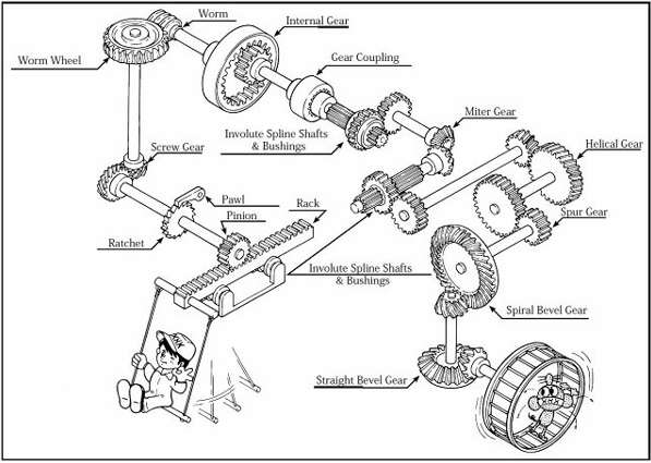
Figure.5.1. Overview of Gears
The types of gears are:
(a) Parallel
(b) Intersecting
(c) Non-intersecting and Non-parallel
2. According to peripheral velocity of the gears:
(a) Low Velocity
(b) Medium Velocity
(c) High Velocity
3. According to the type of gearing:
(a) External gearing
(b) Internal gearing
(c) Rack and Pinion
4. According to the position of teeth on Gear Surface
(a) Straight
(b) Inclined
(c) Curved
(a) Parallel Gears: The two parallel and two-dimensional shafts connected by the gears. These gears area unit known as spur gears and also the arrangement is thought as spur geartrain. These gears have teeth parallel to the axis of the wheel. once the teeth area unit is inclined to the axis then they're called voluted gears.
(b) Intersecting shafts: The two non-parallel or across two-dimensional shafts connected by gears are shown in figure.5.3. These gears area unit known as bevel gears and arrangement is understood as bevel power train. The bevel gears like spur gears might have conjointly teeth inclined to the face of bevel within which case they're called whorled bevel gears. this kind of power train is additionally called whorled bevel gears.
(c) The two non-intersecting and non-parallel shafts i.e., non-coplanar shafts connected by gears is shown in figure.5.3. These gears square measure skew bevel or spiral gears and therefore the arrangement is thought as skew bevel or spiral gears and arrangement is thought as skew bevel or spiral gears.
2) The gears having a rate but three m/s square measure referred to as low-rate gears and gears having a rate between three and fifteen m/s square measure referred to as medium rate gears. If the speed of gears is quite fifteen m/s then these square measures are referred to as high-speed gears.
3) In the external gear train, the gear of the 2 shafts mesh outwardly with one another. The larger of those 2 wheels is a spur gear and the smaller one is thought of as pinion. In associate degree, external geartrain motion of the 2 wheels is usually not like. In the internal gear train, the gear of the 2 shafts meshes internally with one another. The larger of those 2 wheels is termed a ring-shaped wheel and the smaller wheel is termed pinion. The motion of the wheels is like in these forms of shafts.
4) According to the position of teeth surface gears square measure classified as straight, curving, or inclined. The gears clarification is given in the next topics alongside necessary diagrams.
Key Takeaways:
Gear classification, understanding of types, application, intersecting, non-intersecting, and parallel shafts.
Terminology
Spur gears have their teeth parallel to the axis Fig.5.2 and area unit used for transmission power between 2 parallel shafts. they're straightforward in construction, simple to manufacture, and valueless. they need higher potency and glorious preciseness rating. they're utilized in high speed and high load application altogether varieties of trains and a good vary of rate ratios.
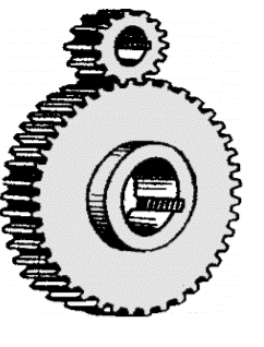
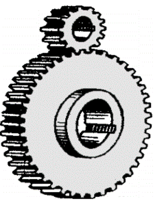
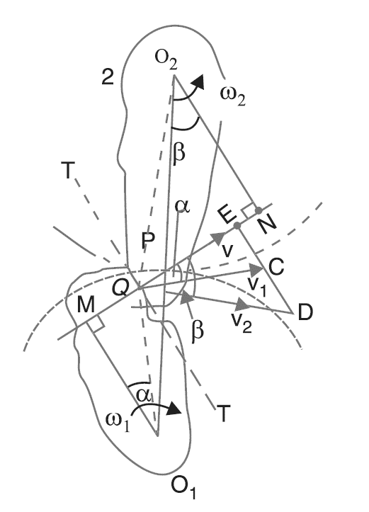
Figure.5.2 Spur Gears
Law of Gearing
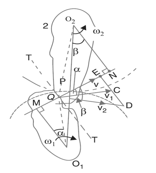
Figure.5.3. Law of Gearing
 ,
, 


Also, from similar triangles O1MP and O2NP

Combining equations, we have

From above, we tend to see that the angular speed magnitude relation is reciprocally proportional to the magnitude relation of the distances of the purpose P from the centers O1 and O2, or the common traditional to the 2 surfaces at the purpose of contact letter intersects the road of centers at point P that divides the middle distance reciprocally because of the magnitude relation of angular velocities. Therefore, to possess a relentless angular speed magnitude relation for all positions of the wheels, purpose P should be the fastened point (called pitch point) for the 2 wheels.
In alternative words, the common traditional purpose of contact between a combination of teeth should tolerate the pitch point. this can be the basic condition that should be happy whereas coming up with the profiles for the teeth of substances wheels. it's additionally called the law of geartrain.
Notes: 1. The higher than condition is consummated by teeth of an involute kind, as long as the foundation circles from that the profiles square measure generated square measure tangential to the common traditional.
2. If the form of 1 tooth profile is indiscriminately chosen and another tooth is intended to satisfy the higher than condition, then the second tooth is alleged to be conjugate to the primary. The conjugate teeth don't seem to be in common use attributable to the problem in the manufacture, and value of production.
3. If D1 and D2 square measure pitch circle diameters of wheels one and a couple of having teeth T1 and T2 severally, then speed magnitude relation,

The involute and cycloidal tooth profile

Figure.5.4. Cycloidal Profile
Types of cycloidal profile: -
1. Epicycloidal profile
2. Hypocycloidal profile
1. Elicycloidal profile:
If the circle rolls without slipping outside the base circle the curve traced by a point on the circumference is called “epicycloid” and the profile are said as “epicycloidal profile”.
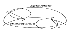
Figure.5.5 Epicycloid and Hypocycloid
2. Hypocycloidal profile:
If a circle rolls without slipping inside the base circle the curve traced by the point on the circumference of the base circle is known as ‘hypocycloid’ and the profile is known as ‘hypocycloidal profile’.
Involute Profile
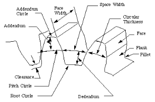
Figure.5.5. Involute Profile
Path of Contact
The path is derived from the contact purpose of a combination of tooth profiles. The pinion one is that the driver and is rotating clockwise. The wheel a pair of is driven within the counter-clockwise direction. EF is their common tangent to the bottom circles. Contact of the 2 teeth is created wherever the postscript circle of the wheel meets the road of action EF, i.e., at C, and is broken wherever the postscript circle of the pinion meets the road of action, i.e., at D. CD is then the trail of contact.

Figure.5.6. Path of Contact
Let r = pitch circle radius of the pinion
R = pitch circle radius of the wheel, ra = addendum circle radius of the pinion
Ra = addendum circle radius of the wheel.
Path of contact = path of approach + path of recess
CD = CP + PD
= (CF-PF) +(DE-PE)

Observe that the path of approach can be found in the dimensions of the driven wheel are known. Similarly, the path of the recess is known from the dimensions of the driving wheel.
Arc of Contact
Arc FK is equal to the path FP as the point P is on the generator FP that rolls on the base circle FHK to generate the involute PK. Similarly, arc FH = Path FC.
Arc of recess = PP" = Tang. vel. of P x Time of recess
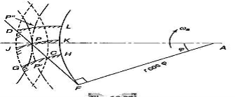
Figure.5.7. Arc of Contact
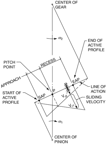
Sliding Velocity
Sliding velocity is the relative velocity in a transverse plane of a common contact point between mating gear teeth. As shown in Fig.5.8, it is the vectorial difference between the two rolling velocities that are tangential to the tooth profiles and perpendicular to the line of action.
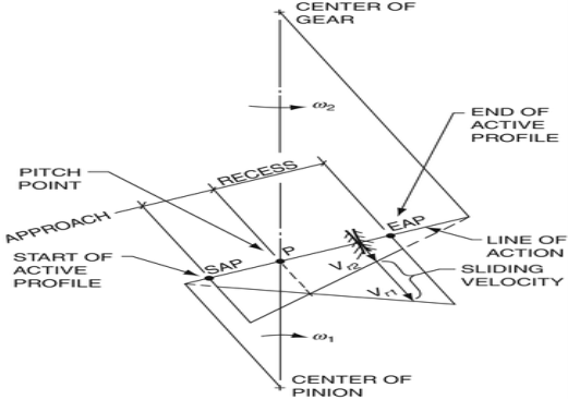
Figure.5.8. Sliding Velocity
Interference and undercutting
Fig. shows a pinion with center O1, in mesh with wheel or gear with center O2.
• MN is that the common tangent to the bottom circles and KL is that the path of contact between the 2 coupling teeth.
• The tip of the tooth on the pinion can then undercut the tooth on the wheel at the basis and take away a part of the involute profile of the tooth on the wheel. This impact is understood as interference and happens once the teeth are being cut.
• In brief, the development once the tip of the tooth undercuts the basis on its coupling gear is understood as interference.
• A touching thought can show, that if the radius of the postscript circle of the pinion is accumulated to O1N, the purpose of contact L can move from L to N.
• Once this radius is additional accumulated, the purpose of contact L is going to be on the within of base circle of wheel and not on the involute profile of tooth on the wheel.
•The tip of the tooth on the pinion can then undercut the tooth on the wheel at the basis and remove a part of the involute profile of the tooth on the wheel. This impact is understood as interference and happens once the teeth are being cut.
• In brief, the development once the tip of the tooth undercuts the basis on its coupling gear is understood as interference.
|
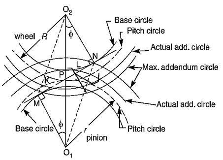
Figure.5.9. Interference
Similarly, if the radius of the postscript circle of the wheel will increase on the far side O2M, then the tip of the tooth on the wheel can cause interference with the tooth on the pinion. The points M and N area unit is known as interference points.
• From the higher than discussion, we tend to conclude that the interference could solely be avoided if the purpose of contact between the 2 teeth is usually on the involute profiles of each of the teeth. In different words, interference could solely be prevented, if the postscript circles of the 2 union gears cut the common tangent to the bottom circles between the points of tangency.
• When interference is simply avoided, the utmost length of the path of contact is MN once the utmost matter circles for pinion and wheel have the points of tangency N and M severally as shown in Fig. Obviously, interference could also be avoided if the trail of contact doesn't extend on the far side interference points. The limiting price of the radius of the matter circle of the pinion is O1N and of the wheel is O2M.
Minimum number of Teeth to avoid Interference
• The arc of contact is the length of the pitch circle traversed by a point on it during the mating of a pair of teeth.
• Thus, all the teeth lying in between the arc of contact will be meshing with the teeth on the other wheel.
Therefore, the number of teeth in contact =

contact ratio.
wheel must be in contact with another tooth of the second wheel.
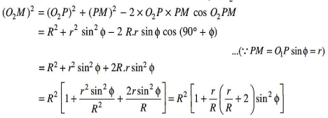
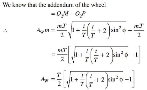
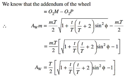
We have already discussed that to avoid interference, the addendum
circles for the two mating gears must cut the common tangent to the base circles
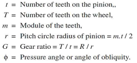
between the points of tangency. The limiting condition reaches when the
addendum circles of pinion and wheel pass-through point N and M
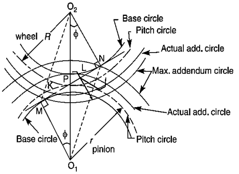
Figure.5.10. Tooth Profile





Force Analysis
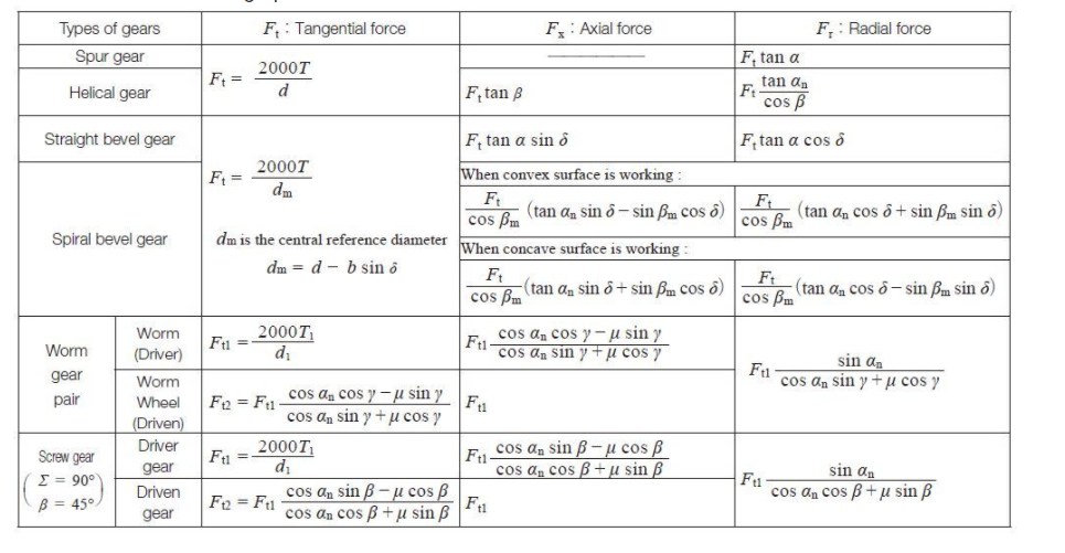
When the gear mesh transmits power, forces act on the gear teeth. As shown in Figure five.11, if the coordinate axis of the orthogonal 3-axes denotes the gear shaft, forces square measure outlined as follows: The force that acts within the coordinate axis direction is outlined because of the tangential force, Ft(N). The force that acts within the coordinate axis direction is outlined because of the radial force, Fr(N) The force that acts within the coordinate axis direction is outlined because of the axial force Fx (N) or thrust. Analyzing these forces is extremely necessary once coming up with gears. In coming up with gear, it's necessary to research these forces acting upon the gear teeth, shafts, bearings, etc.
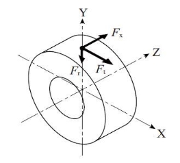
Figure.5.11. Force Analysis
Table.5.1: Forces acting on a Gear
Key Takeaways:
Spur gear definition, spur gear nomenclature, geometry, minimum number of teeth to avoid interference, Interference and undercutting, Force analysis, Force acting on a gear.
The teeth on volute gears are cut at Associate in Nursing angle to the face of the gear • This gradual engagement makes volute gears operate far more swimmingly and quietly than spur gears. • One attention-grabbing issue regarding volute gears is that if the angles of the gear teeth are ar correct, they will be mounted on perpendicular shafts, adjusting the rotation angle by ninety degrees.
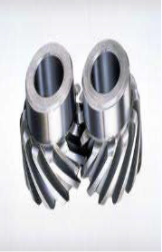
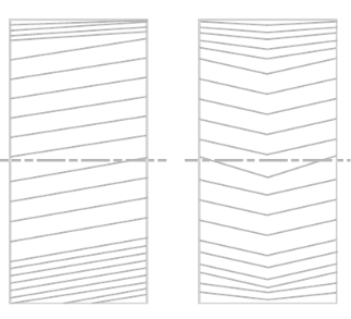
Figure.5.12. Helical Gears
5.3.1. Terminology
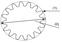
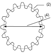
A helical gear has two major circles: 1) the outside circle and 2) the pitch circle.
The outside circle is the distance around the outer edge of the gear’s teeth.
The diameter of the outside circle is called the outside diameter. (Figure.5.13).
The pitch circle is the imaginary circle found at the point where the teeth of two gears mesh.
Terms used in Helical Gears:
1. Helix angle: It is a constant angle made by the helices with the axis of rotation.
2. Axial pitch: It is the distance, parallel to the axis, between similar faces of adjacent teeth. It is the same as circular pitch and is therefore denoted by Pc. The axial pitch may also be defined as the circular pitch in the plane of rotation or the diametral plane.
3.Normal pitch: The normal pitch of a helical gear is the pitch of the tool used to cut the teeth. It is measured in a plane perpendicular to the direction of the teeth
Normal diametral pitch (D.P.) = 3.146 (Normal circular pitch (C.P.))
4.Transverse Pitch: The transverse pitch of a helical gear corresponds to the pitch of spur gear with the same number of teeth and the same pitch diameter.
Transverse diametral pitch (D.P) = 3.1416 (Transverse circular pitch (C.P.))
5. Normal Pressure Angle: Normal pressure angle is the pressure angle in the normal plane of a helical gear tooth.
| ||
|
| |
| ||
Figure.5.13. Outside Diameter & Pitch Circle (Left and Right respectively)
5.3.2 Geometrical Relationships
For helical gears, a reference helix is defined by a helix angle, β, at the theoretical pitch diameter. The sign of the helix angle determines the hand of the helix, with positive (+) being right-hand. The diagram below illustrates the helix angle, not to be confused with the helix lead angle.
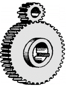
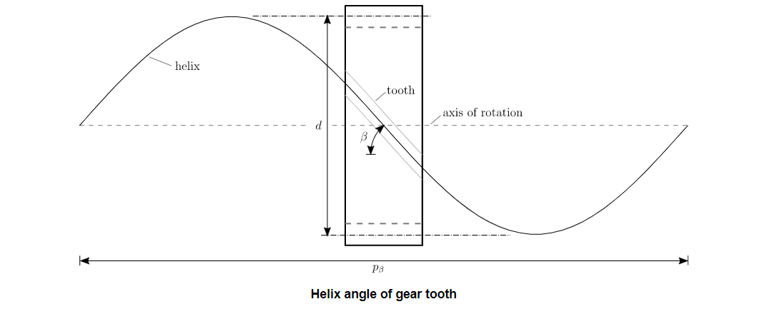
Figure.5.14. Helix Angle of gear tooth
If we imagine unwrapping the helix curve along its helix angle, we can derive an expression for the helix pitch length as a function of helix angle and theoretical pitch diameter:

and by acknowledging the helix pitch length as a constant regardless of diameter, the helix angle at an arbitrary diameter, dy, is:

For the pure mathematics of a voluted gear, the angle varies as a operate of the radius.
This is determined in a very voluted gear tooth since the involute profile spans over a variety of diameters. This ends up in the angle at the bottom diameter being but at the tip diameter. this can be notably vital once considering contact on the tooth surface and therefore the ensuing forces of a voluted gear combine.
Gear Teeth
This section reviews the geometric properties of whorled gear teeth. A living proof is provided at the end of the section.
To understand the pure mathematics of a whorled gear, it's applicable to think about each of the transversal and traditional planes. These distinct planes exist because of the whorled form of the gear teeth. within the case of spur gears, these planes are coincident since β=0°.
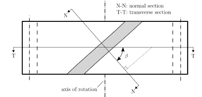
Figure.5.15. Transverse and Normal Plane
Lengths in the transverse and normal planes are related by helix angle according to:

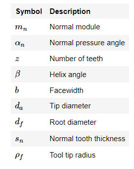
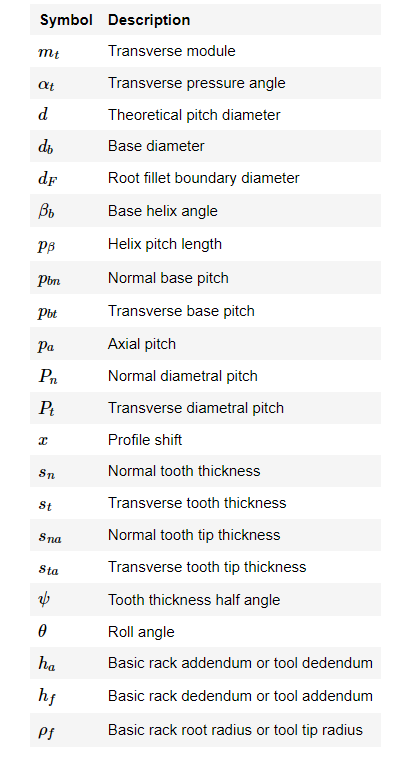
This table provides a set of input parameters commonly used to define the geometry of helical gear teeth.
Basic Parameters
The basic parameters process the pure mathematics of turbinate gear teeth square measure traditional module, traditional pressure angle, variety of teeth, and angle. Symbolically, each is denoted as m, αn, Zn, and β, severally. completely different basic parameters may well be used, however these square measures the foremost common.
Module
The module is a defining parameter of gear tooth size, with units of mm. Module values exist in both the normal and transverse planes. Geometrically, it is easiest to understand the transverse module, expressed as millimeters of theoretical pitch diameter per tooth:

As a function of basic parameters, the transverse module is calculated as:

By examining a transverse section of a helical gear, we can derive the transverse pitch and its relationship to the module.
where the transverse pitch equals:

Diametral pitch, Pd, is the module equivalent parameter used with the system of imperial units, with units of in-1:

Pressure Angle
Since helical gears are a form of cylindrical involute gears, the pressure angle at the theoretical pitch diameter is used as a defining parameter. Geometrically, it is easiest to understand the transverse pressure angle as illustrated below.
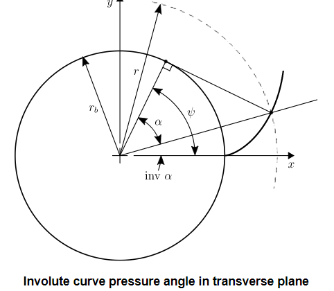
Figure.5.16. Involute curve pressure angle
The transverse pressure angle can be calculated as a function of the normal pressure angle and helix angle:

The pressure angles explained here are sometimes called reference values since they refer to the pressure angles associated with the theoretical pitch diameter. Recall, involute pressure angle changes as a function of diameter. In a later section, the working pressure angle of a gear pair is explained.
From the previous figure, a useful equation for transverse pressure angle at an arbitrary diameter, dy, is derived as:

The helix angle ψ is always measured on the cylindrical pitch surface. ψ value is not standardized. It ranges between 15 and 45
 . Commonly used values are 15,23, 30, or 45
 . Lower values give less end thrust. Higher values result in smoother operation and more end thrust. Above 45
 is not recommended.
Virtual Number of Teeth for Helical Gears
The circular pitch (p) and pressure angle (α) are measured in the plane of rotation, as in spur gears. These quantities in the normal plane are denoted by suffix n (pn, αn) n (pn, αn) as shown in fig below. It may be observed,
pn=p cosφ, pn=p cosφ, Normal module mn is=m cos φ. A normal module is used for hob selection. The pitch diameter (d) of the helical gear is d=Z mn/cosφ
The axial pitch (pa)(pa) is (pa)=p/tanφ(pa)=p/tanφ
In the case of a helical gear, the resultant load between mating teeth is always perpendicular to the tooth surface. Hence bending stresses are computed in the normal plane, and the strength of the tooth as a cantilever beam depends on its profile in the normal plane. Fig. 5.17 shows the view of a helical gear in the normal and transverse plane.
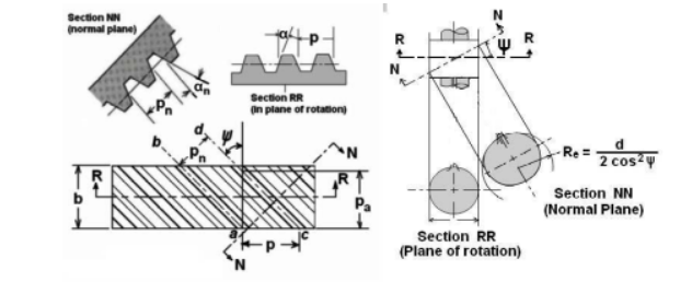
Figure.5.17. Transverse Plane
The first figure shows the pitch cylinder and one tooth of a helical gear. The normal plane intersects the pitch cylinder in an ellipse. If ‘d’ is the pitch diameter of the helical gear, the major and minor axes of the ellipse will be d/cosφ and d. The radius of curvature 'Re' at the extremes of the minor axis from coordinate geometry is found to be d/2cosφ2.
The shape of the tooth in the normal plane is nearly the same as the shape of a spur gear tooth having a pitch radius equal to radius Re of the ellipse.

Substituting Re, mn=m cosφ, Re, mn=m cosφ, and d=Zm

Key Takeaways:
Helical and spiral gears definition, terminology, geometrical relationships, nomenclature, formula for virtual number of teeth on helical gears.
Bevel gears are cut on conical blanks to be used to transmit motion between intersecting shafts. The simplest bevel gear type is the straight-tooth bevel gear or straight bevel gear as can be seen from Figure.5.18. As the name implies, the teeth are cut straight, parallel to the cone axis, like spur gears.
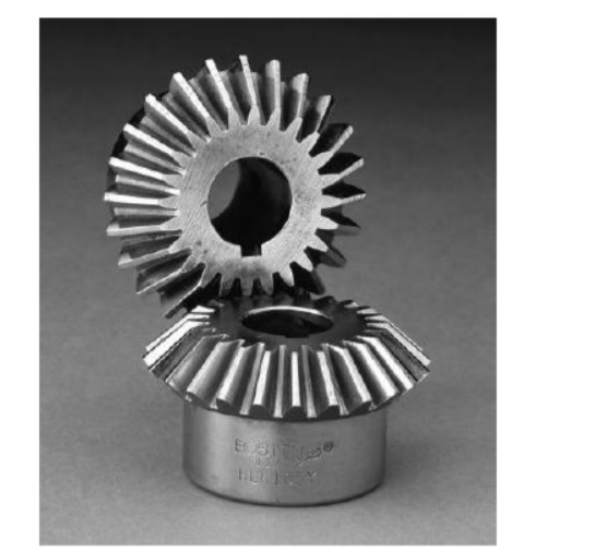
Figure.5.18. Bevel Gears
Geometrical Relationships for Bevel and Worm Gears
The geometry of bevel gears is shown in Figure (5.19). The size and shape of the teeth are defined at the large end on the back cones. They are similar to those of spur gear teeth. Standard straight bevel gears are cut by using a 20° pressure angle and full-depth teeth, which increase the contact ratio and the strength of the pinion. The diametral pitch refers to the back- cone of the gear. Therefore, the relationships between the geometric quantities and the speed for bevel gears are given as follows:
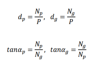
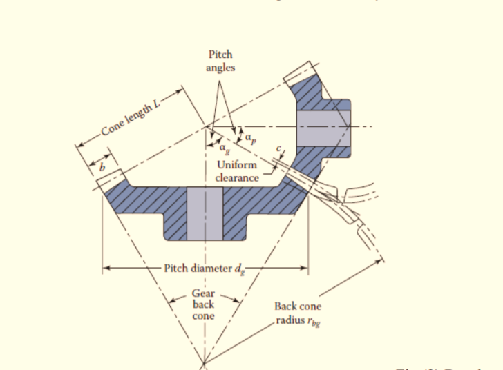
Figure.5.19 Bevel Gears

Where,
d = the pitch diameter
P = the diametral pitch
N = the number of tooth
α = the pitch angle
ω = the angular speed
rs = the speed ratio.
It is to be noted that, for 20 pressure angle straight bevel gear teeth, the face width (b) should be made equal to:

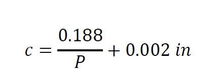
whichever is smaller, The, uniform clearance is given by the following formula:
5.4.2. Worm and Worm Wheel
Worm gears are gears that are widely used for transmission power at high-speed ratios between non-intersecting shafts that are typically, however not essentially, at right angles.
• It will provide speed ratios as high as 300:1 or a lot of.
• It's largely used as a speed reducer, that consists of worm and worm wheel or gear.
• The gear or gear is analogous to a volute gear with a face arciform to conform to the form of the worm.
TYPES OF WORMS
There are two types of worms. They are as follows:
1. Cylindrical or straight worm.
2. Cone or double enveloping worm.
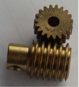
Figure.5.20 Worm Wheel
TYPES OF WORM GEARS
The important three types of worm gears are given below:
1.Straight face worm gear
2.Hobbed straight face worm gear
3.Concave face worm gear
Terms Used
• Axial pitch: It is also known as the linear pitch of a worm. It is the distance measured axially from a point on one thread to the corresponding point on the adjacent point on the worm.
• Lead: It is the linear distance through which a point on a thread
moves ahead in one revolution of the worm.
• Lead angle: It is the angle between the tangent to the thread helix
on the pitch cylinder and the plane normal to the axis of the worm. It
is denoted by λ.

Figure.5.21. Development of Helix Thread
Geometry is shown in the following images:
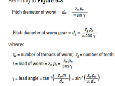
Figure.5.22. Geometry
Key Takeaways:
Geometrical relationship for bevel and worm gears, Nomenclature, Terminology, geometry for worm and worm wheel.
Sometimes, two or more gears are made to mesh with each other to transmit power from one shaft to another. Such a combination is called a gear train or train of toothed wheels.
5.5.1 Types
Following are the different types of gear trains, depending upon the arrangement of wheels:
1. Simple gear train, 2. Compound gear train, 3. Reverted
gear train, and 4. Epicyclic gear train.
In the first three types of gear trains, the axes of the shafts over which the gears are mounted are fixed relative to each other. But in the case of epicyclic gear trains, the axes of the shafts on which the gears are mounted may move relative to a fixed axis.
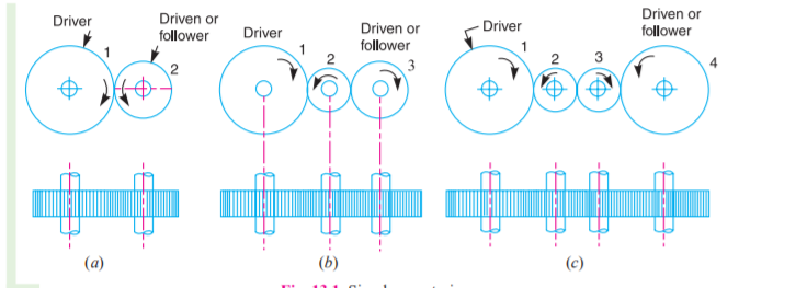
Figure.5.23. Simple Gear Train
When there's just one gear on every shaft, as shown in Fig. 5.23, it's called an easy gear train. The gears square measure drawn by their pitch circles. Since the speed quantitative relation (or rate quantitative relation) of the gear train is that the quantitative relation of the speed of the driving force to the speed of the driven or follower and ratio of speeds of any try of gears in the mesh is that the inverse of their variety of teeth, therefore

It may be noted that the ratio of the speed of the driven or follower to the speed of the driver is known as the training value of the gear train. Mathematically,

When there is over one gear on a shaft, as shown in Fig. 5.24, it's known as a compound train of substances.
But whenever the gap between the motive force and also the driven or follower should be bridged over by intermediate gears and at the constant time a good (or abundant less) speed quantitative relation is needed, then the advantage of intermediate gears is intense by providing compound gears on intermediate shafts. during this case, every intermediate shaft has 2 gears stiffly mounted that so that they will have a constant speed.
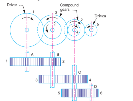
Figure.5.24. Compound Gear Train
5.5.2. Analysis of Epicyclic Gear Trains
We have already mentioned that in associate degree planetary gear train, the axes of the shafts, over that the gears area unit mounted, could move relative to a hard and fast axis. a straightforward planetary gear train is shown in Fig.5.25, wherever a gear A and therefore the arm C have a standard axis at O1 regarding that they will rotate. The gear B meshes with gear A and has its axis on the arm at O2, regarding that the gear B will rotate. If the arm is fastened, the gear train is straightforward and equipment A will drive gear B or vice-versa, however, if gear A is fastened and therefore the arm is revolved regarding the axis of drugs A (i.e., O1), then the gear B is forced to rotate upon and around gear A. Such a motion is termed circle and therefore the gear trains are organized in such a way that one or additional of their members move upon and around another member area unit called planetary gear trains (epi. means that upon and cyclic means that around). The planetary gear trains are also easy or compound. The planetary gear train area unit helps send high-speed ratios with gears of moderate size during a relatively lesser area. The planetary gear trains area unit employed in the rear gear of shaping machine, differential gears of the cars, hoists, simple machine blocks, wrist joint watches, etc.
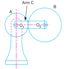
Figure.5.25. Epicyclic Gear Train
The following two methods may be used for finding out the velocity ratio of an epicyclic gear train.
These methods are discussed, in detail, as follows: 1. Tabular method. Consider an epicyclic gear train as shown in Fig. 5.25.
Let TA = Number of teeth on gear A and TB = Number of teeth on gear B. First of all, let us suppose that the arm is fixed. Therefore, the axes of both the gears are also fixed relative to each other. When gear A makes one revolution anticlockwise, the gear B will make *TA / TB revolutions, clockwise. Assuming the anticlockwise rotation as positive and clockwise as negative, we may say that when gear A makes + 1 revolution, then the gear B will make (– TA/ TB) revolutions. This statement of relative motion is entered in the first row of the table (see Table). Secondly, if gear A makes + x revolutions, then the gear B will make – x × TA / TB revolutions. This statement is entered in the second row of the table. In other words, multiply each motion (entered in the first row) by x. Thirdly, each element of an epicyclic train is given + y revolutions and entered in the third row. Finally, the motion of each element of the gear train is added up and entered in the fourth row
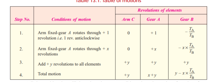
The given knowledge within the third column of the fourth row. 2. algebraical technique. during this technique, the motion of every part of the epicyclic gear train relative to the arm is ready down within the kind of equations. the amount of equations depends upon the number of components within the gear train. however, the 2 conditions square measure, usually, equipped in an epicyclic gear train viz. some part is mounted and therefore the alternative has such as motion. These 2 conditions square measure spare to unravel all the equations; and therefore, to work out the motion of any part within the planet wheel train. Let the arm C be mounted in the associate planet wheel train as shown in Fig. 13.6. Therefore, the speed of gear A relative to the arm C
= NA – NC
and speed of the gear B relative to arm C,
= NB – Nc
Since gears A and B are meshing directly, therefore they will revolve in opposite directions.

Since the arm C is fixed, therefore its speed, Nc = 0.

If gear A is fixed, then NA= 0.

When the rotating parts of an epicyclic gear train, as shown in Fig.5.26, have no angular acceleration, the gear train is kept in equilibrium by the three externally applied torques, viz. 1. Input torque on the driving member (T1), 2. Output torque or resisting or load torque on the driven member (T2), 3. Holding or braking or fixing torque on the fixed member (T3). |
The net torque applied to the gear train must be zero. In other words,
T1 + T2 + T3 = 0 ...(i)
∴ F1 .r1 + F2.r2 + F3.r3 = 0 ..(ii)
where F1, F2, and F3 are the corresponding externally applied forces at radii r1, r2, and r3. Further, if ω1, ω2, and ω3 are the angular speeds of the driving, driven and fixed members respectively, and the friction be neglected, then the net kinetic energy dissipated by the gear train must be zero, i.e.
T1.ω1 + T2.ω2 + T3.ω3 = 0 ...(iii)
But, for a fixed member, ω3 = 0 ∴ T1.ω1 + T2.ω2 = 0
5.5.4 Torque on Sun and Planetary Gear Train & Compound Epicyclic Gear Trains
A compound epicyclical gear train is shown in Fig. It consists of 2 co-axial shafts S1 and S2, associate annulus gear A that is fixed, the compound gear (or planet gear) B-C, the gear D and the arm H. The annulus gear has internal teeth and therefore the compound gear is carried by the arm and revolves freely on a pin of the arm H. The gear is co-axial with the annulus gear and therefore the arm but freelance of them. The annulus gear A meshes with the gear B and therefore the sun gear D meshes with the gear C. it should be noted that once the annulus gear is mounted, the gear provides the drive and once the sun gear is mounted, the annulus gear provides the drive. In each cases, the arm acts as an follower.
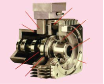
Figure.5.26. Sun and Planet Gear
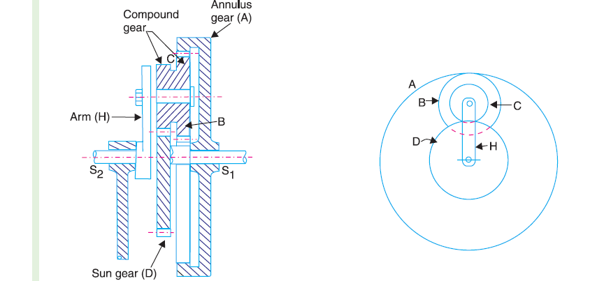
Figure.5.26. Compound Gear Train
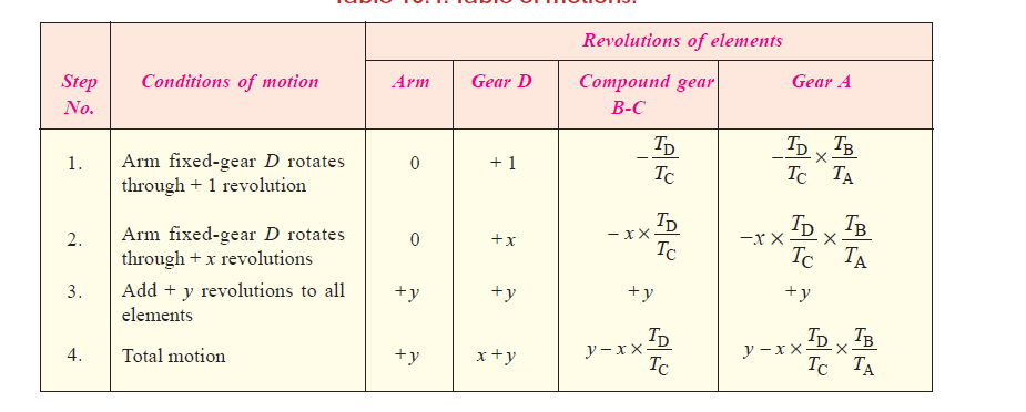
Let TA, TB, TC, and TD be the teeth and NA, NB, NC and ND be the speeds for the gears A, B,C and D respectively. A little consideration will show that when the arm is fixed and the sun gear D is turned anticlockwise, then the compound gear B-C and the annulus gear A will rotate in the clockwise direction.
The motion of rotations of the various elements are shown in the table below.
Key Takeaways:
Types of gear train, Analysis of Epicyclic gear trains, Holding torque on simple, compound and epicyclic gear trains, torque on sun and planetary gear train,
Compound epicyclic gear train
Reference Books:
2. Bevan T, “Theory of Machines”, Third Edition, Longman Publication |
|
3. Paul E. Sandin, “Robot Mechanisms and Mechanical Devices Illustrated”, Tata McGraw Hill Publication
|
4. Ghosh Malik, “Theory of Mechanism and Machines”, East-West Pvt. Ltd.
|
5. M.P. Groover, “Automation, production systems, and computer-integrated manufacturing”, Prentice-Hall of India Pvt. Ltd.
