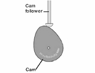
Figure.6.1 Cam with follower
Types of cams
Cams can be classified based on their physical shape.
a) Disk or plate cam: The disk (or plate) cam has an associate degree irregular contour to impart a selected motion to the follower. The follower moves in an exceedingly plane perpendicular to the axis of rotation of the camshaft and is a command in grips with the cam by springs or gravity.
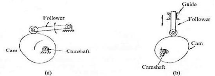
Figure.6.2. Disk or Plate Cam
b) Cylindrical cam: The cylindrical cam contains a groove cut on its cylindrical surface. The roller follows the groove, and therefore the follower moves during a plane parallel to the axis of rotation of the cylinder.
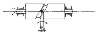
Figure.6.3. Cylindrical Cam
c) Translating cam: The translating cam may be a contoured or grooved plate slippery on a guiding surface(s). The follower could oscillate (Fig.6.4. a) or reciprocate (Fig.6.4.b). The contour or the form of the groove is decided by the desired motion of the follower.

Figure.6.4 Translating Cam
Types of followers:
(i) Based on the surface in contact:
(a)Knife edge follower
(b)Roller follower
(c)Flat faced follower
(d)Spherical follower
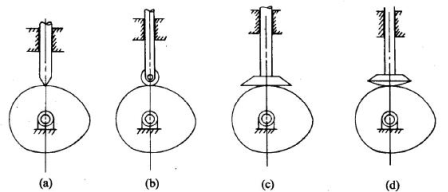
Figure.6.5: Followers
(i) Based on the type of motion:
(a) Oscillating follower
(b) Translating follower
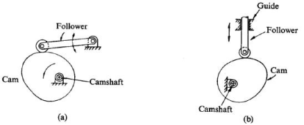
Figure.6.6: Oscillating and Translating Follower
Based on the line of motion:
(a) Radial follower: The lines of movement of in-line cam followers pass through the centers of the camshafts.
(b) Off-set follower: For this type, the lines of movement are offset from the centers of the Camshafts.
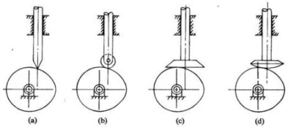
Figure.6.7.: Radial Follower & Offset Follower
NOMENCLATURE OF CAMS
Cam Profile The contour of the working surface of the cam.
Trace Point The point at the knife-edge of a follower, or the center of a roller, or the center of a spherical face.
Pitch Curve The path of the tracer point.
Base Circle The smallest circle drawn, tangential to the cam profile, with its center on the axis of the camshaft. The size of the base circle determines the size of the cam.
Prime Circle The smallest circle drawn, that can be drawn from the center of the cam and tangent to the pitch curve.
Prime circle radius = Base circle radius for knife-edge and flat-faced follower
Prime circle radius = Base circle radius + radius of roller for a roller follower
Pressure Angle The angle between the normal to the pitch curve and the direction of motion of the follower at the point of contact.
Lift of stroke: It is the maximum travel of the follower from its lowest position to the topmost position. The maximum rise is called lift.
Pitch Point: It is a point on the curve having a maximum pressure angle.
Pitch Circle: It is the circle drawn from the center of the cam through the pitch points.
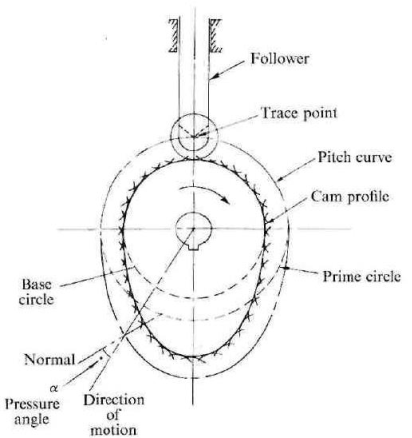
Figure.6.8. Cam Nomenclature
Types of follower motion:
Cam follower systems are designed to realize a desired oscillating motion. applicable displacement patterns are to be designated for this purpose, before coming up with the cam surface. The cam is assumed to rotate at a continuing speed and therefore the follower raises, dwells, returns to its original position, and dwells once more through such as angles of rotation of the cam, throughout every revolution of the cam. a number of the quality follower motions are as follows:
They are, follower motion with,
(a) Uniform velocity
(b) Modified uniform velocity
(c) Uniform acceleration and deacceleration
(d) Simple harmonic motion
(e) Cycloidal motion
Displacement diagrams:
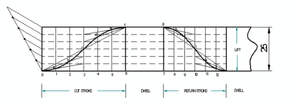
In a cam-follower system, the motion of the follower is incredibly vital. Its displacement is often premeditated against the angular displacement θ of the cam and it's referred to as because of the displacement diagram. The displacement of the follower is premeditated on the y-axis and angular displacement θ of the cam is premeditated on the coordinate axis. From the displacement diagram, rate y and acceleration of the follower may also be premeditated for various angular displacements θ of the cam. The displacement, rate, and acceleration diagrams square measure premeditated for one cycle of operation i.e., one rotation of the cam. Displacement diagrams square measure basic needs for the development of cam profiles. Construction of displacement diagrams and calculation of velocities and accelerations of followers with differing kinds of motions square measure mentioned within the following sections.
(a) Follower motion with Uniform velocity:
Fig.6.9. shows the displacement, speed, and acceleration patterns of an addict having uniform speed sort of motion. Since the follower moves with constant speed, throughout rising and fall, the displacement varies linearly with θ. Also, since the speed changes from zero to a finite price, in no time, on paper, the acceleration is coming back in finite at the start and finish of rising and fall.
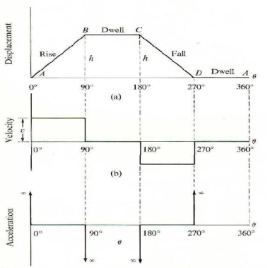
Figure.6.9. Displacement Diagram
Follower motion with modified uniform velocity:
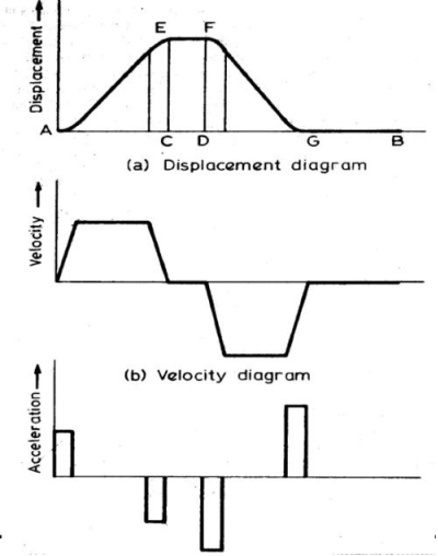
Figure.6.10. Displacement, Velocity, and Acceleration
b) Simple Harmonic Motion: In fig., the motion executed by point Pl, which is the projection of point P on the vertical diameter is called simple harmonic motion. Here, P moves with uniform angular velocity ωp, along a circle of radius r (r=s/2).
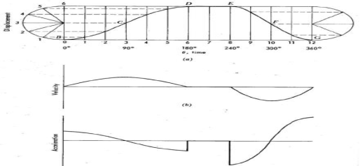
Figure.6.11. Simple Harmonic Motion
(c) Cycloidal motion:
A cycloid is a path generated by a point on the circumference of a circle, as the circle rolls without slipping, on a straight/flat surface. The motion executed by the follower here, is similar to that of the projection of a point moving along a cycloidal curve on a vertical line as shown in figure.6.12.
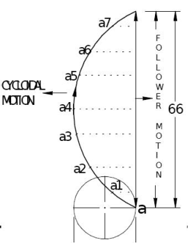
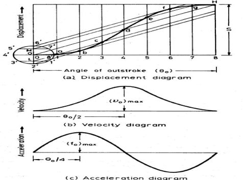
Figure.6.12. Cycloidal Motion
(d) Retardation (UARM):
Here, the displacement of the follower varies parabolically with respect to the angular displacement of the cam. Accordingly, the velocity of the follower varies uniformly with respect to the angular displacement of the cam. The acceleration/retardation of the follower becomes constant accordingly.
Maximum acceleration of follower on the outstroke & return stroke,

Maximum velocity of the follower on the outstroke & return stroke,

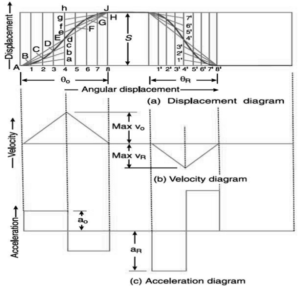
Figure.6.13. UARM
Example:
Draw the cam profile for the following conditions:

Cam profile:
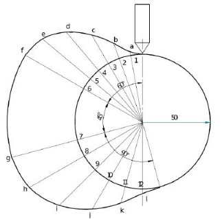
Cam profile with 10 mm offset:
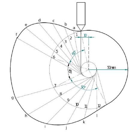
Draw the cam profile for the following conditions:
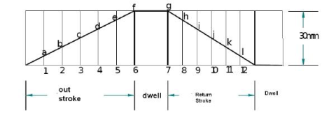
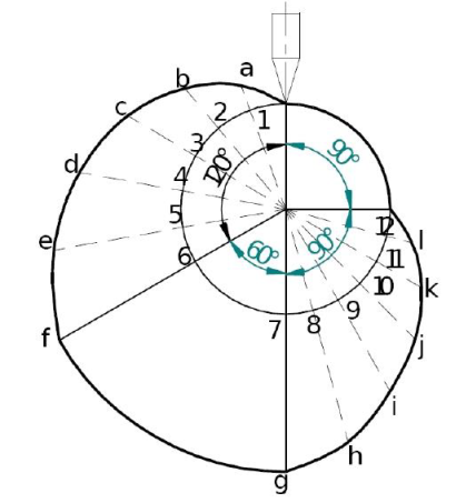
Follower type=knife edged follower, in line; lift=30mm; base circle radius =20mm; outstroke with uniform
velocity in 120°of cam rotation; dwell for 60°; return stroke with uniform velocity, during 90°of cam
rotation; dwell for the remaining period.
Displacement Diagram
Cam profile
Cam Profile Construction for Roller Follower:
We can draw and understand the cam profile for roller follower by the following example:
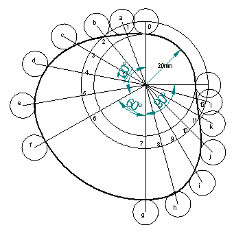
Draw the cam profile for the following condition:
Follower type = roller follower, in-line; lift = 25mm; base circle radius = 20mm; roller radius = 5mm; out stroke with UARM, for 1200 cam rotation; dwell for 600 cam rotation; return stroke with UARM, for 900 cam rotation; dwell for the remaining period. Determine max. velocity and acceleration during out stroke and return stroke if the cam rotates at 1200 rpm in a clockwise direction.
Displacement diagram:
Cam profile: Construct base circle and prime circle (25mm radius). Mark points 1,2,3 in a direction opposite to the direction of cam rotation, on the prime circle. Transfer points a,b,c from displacement diagram. At each of these points a, bc draw circles of 5mm radius, representing rollers. Starting from the first point of contact between roller and base circle, draw a smooth freehand curve, tangential to all successive roller positions. This forms the required cam profile.
Cam Jump Phenomenon:
We know o.k. that a (reciprocating)cam and follower is usually wont to attain mutual motion within the vertical direction in any system. Example. (IC Engine Valve Operation) In most of the cams like disc cams, plate cams, the cam is to blame for the upward movement of the follower. however curiously the cam isn't to blame for the downward movement (return) of the follower. rather than the cam, acceleration because of gravity “g” is to blame for the downward motion. As we know, “g” is restricted by nine.81 m/s2. Here comes the matter, if the motion speed of the cam is incredibly high, it results in accelerates the follower at a really high rate. No downside regarding the upward acceleration of the follower, the cam can lookout. we tend to cannot expect the cam to maneuver downward in Associate in Nursing acceleration larger than “g”. It makes the follower lose contact with the cam. this is often known as a jumping development.
Key Takeaways:
Cam and its followers, types of cams, types of followers, different types of follower motion like follower motion with uniform velocity, modified uniform velocity, cycloidal motions, cam jump phenomenon, cam profile for roller follower, UARM.
Introduction
Automation is that the use of management systems and knowledge technologies to cut back the requirement for humans add the assembly of products and services. within the scope of manufacture, automation may be a step on the far side of mechanization. Whereas mechanization provided human operators with machinery to help them with the muscular necessities of labour, automation greatly decreases the requirement for human sensory and mental necessities further.
Types of Automation System with examples
Automated production systems can be classified into three basic types:
FIXED AUTOMATION
It is a system during which the sequence of process (or assembly) operations is fastened by the instrumentation configuration. The operations within the sequence are sometimes straightforward. it's the combination and coordination of the many such operations into one piece of apparatus that creates the system advanced. the standard options of fastened automation are:
a. High initial investment for custom–Engineered equipment;
b. High production rates; and
c. comparatively inflexible in accommodating product changes.
The economic justification for fastened automation is found in a product with terribly high demand rates and volumes. The high initial price of the instrumentation may touch an awfully sizable amount of units, therefore creating the cost enticing compared to different strategies of production. samples of fastened automation embody mechanized assembly.
PROGRAMMABLE AUTOMATION
In this, the assembly instrumentality is meant with the potential to vary the sequence of operations to accommodate totally different product configurations. The operation sequence is controlled by a program, that could be a set of directions coded in order that the system will browse and interpret them. New programs are often ready and entered into the instrumentality to supply new merchandise. a number of the options that characterize programmable automation are:
a. High investment in all-purpose equipment;
b. Low production rates relative to mounted automation;
c. Flexibility to handle changes in product configuration; and
d. most fitted for batch production.
Automated production systems that square measure programmable square measure utilized in low and medium volume production. The elements or merchandise square measure usually created in batches. to supply every new batch of a distinct product, the system should be reprogrammed with the set of machine directions that correspond to the new product. The physical setup of the machine should even be modified over: Tools should be loaded; fixtures should be hooked up to the machine table even be modified machine settings should be entered. This transformation procedure takes time. Consequently, the everyday cycle for the given product includes an amount throughout that the setup and reprogramming come about, followed by an amount during which the batch is created. samples of programmed automation embody numerically controlled machine tools and industrial robots.
FLEXIBLE AUTOMATION
It is an associate degree extension of programmable automation. a versatile machine-driven system is one that's capable of manufacturing a range of products (or parts) with just about no time lost for changeovers from one product to consecutive. there's no production time lost whereas reprogramming the system and fixing the physical setup (tooling, fixtures, and machine setting). Consequently, the system will turn out varied mixtures and schedules of the product rather than requiring that they be created in separate batches. The options of versatile automation may be summarized as follows:
1. High investment for a custom-engineered system.
2. Continuous production of variable mixtures of product.
3. Medium production rates.
4. Flexibility to traumatize product style variations.
The essential options that distinguish versatile automation from programmable automation are:
1. the capability to alter half programs with no lost production time; and
2. the aptitude to convert the physical setup, once more with no lost production time.
These options permit the machine-driven production system to continue production while not the period of time between batches that's characteristic of programmable automation. dynamic the half programs are usually accomplished by making ready the programs off-line on a system and electronically transmittal the programs to the machine-driven production system. Therefore, the time needed to try the programming for a consecutive job doesn't interrupt production on this job. Advances in laptop systems technology square measure mostly accountable for this programming capability in versatile automation. dynamic the physical setup between components is accomplished by creating the conversion off-line so moving it into place at the same time because the next half comes into position for the process. the utilization of pallet fixtures that hold the components and transfer them into position at the geographic point is a method of implementing this approach. For these approaches to be successful; the range of components which will be created on a versatile machine-driven production system is sometimes additional restricted than a system controlled by programmable automation. The relative positions of the 3 sorts of automation for various production volumes and merchandise varieties square measure pictured within the following figure.
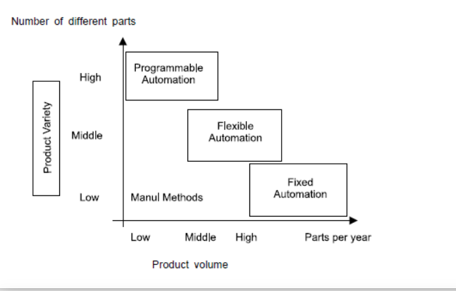
Figure.6.14. Types of Automation Based on Production Volume
Key Takeaways:
Automation definition with examples, types of automation, Fixed, programmable, and flexible automation, comparison of automation by the diagram.
1) Continuous Transfer
2) Intermittent or Synchronous Transfer
3) Asynchronous or power and Free Transfer
These 3 classes square measure distinguished by the sort of motion that's imparted to the workpiece by the transfer mechanism. the foremost acceptable variety of transport system for a given application depends on such factors as:
• The kinds of operation to be performed
• The range of stations on the road
• The weight and size of the work components
• Whether manual stations square measure enclosed on the road
• Balancing the varied method times on the lines
These transfer systems square measure used for each process and assembly operations. within the case of automatic assembly machines, we tend to square measure bearing on the mechanisms that transport the partly completed assemblies between stations, not the feed mechanisms that gift new parts to the assemblies at a selected station. The devices that feed associate degreed orient the parts square measure usually an integral part of the digital computer.
Continuous transfer: With the continual methodology of transfer, the work components square measure moved incessantly at a constant speed. this needs the work heads to maneuver throughout the process to take care of continuous registration with the work half. for a few kinds of operations, this movement of the work heads throughout the process isn't possible. it might be tough, as an example, to use this sort of system on a machining transfer line owing to inertia issues because of the scale and weight of the work heads. In different cases, continuous transfer would be sensible. samples of its use square measure in drinkable bottling operations, packaging, manual assembly operations wherever the human operator will move with ‘the moving flow line, and comparatively easy automatic assembly tasks.
Intermittent transfer: because the name suggests, during this methodology the workpieces square measure transported with associate degree intermittent or discontinuous motion. The workstations square measure mounted in position and also the components square measure moved between stations then registered at the correct locations for the process. All work components square measure transported at the identical time and, for this reason, the term “synchronous transfer system” is additionally accustomed to describe this methodology of labour half transport. samples of applications of the intermittent transfer of labour components will be found in machining operations, press operating operations, or progressive dies.
Asynchronous transfer: this technique of transfer, conjointly cited as a power-and-free system, permits every work half to maneuver to the subsequent station once the process at the present station has been completed. every half moves severally of different components. Hence, some components square measure being processed on the road at the identical time that others square measure being transported between stations. Asynchronous transfer systems supply the chance for larger flexibility than do the opposite 2 systems, and this flexibility will be an excellent advantage in bound circumstances. In-process storage of labor components will be incorporated into the asynchronous systems with relative ease. Power-and-free systems may also make amends for line equalization issues wherever there square measure important variations in method times between stations.
Different Types of Transfer Mechanisms
There are various types of transfer mechanisms used to move parts between stations. These mechanisms can be grouped into two types: those used to provide linear travel for in-line machines, and those used to provide rotary motion for dial indexing machines.
Linear transfer mechanisms
We will explain the operation of three of the typical mechanisms: the walking beam transfer bar system, the powered roller conveyor system, and the chain-drive conveyor system. This is not a complete listing of all types, but it is a representative sample.
WALKING BEAM SYSTEMS: With the walking beam transfer mechanism, the work parts are lifted up from their workstation locations by a transfer bar and moved one position ahead. to the next station. The transfer bar then lowers the parts into nests which position them more accurately for processing. This type of transfer device is illustrated in Figure.6.15.
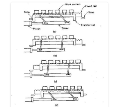
Figure.6.15 Walking Beam Systems
POWERED ROLLER CONVEYOR SYSTEM: Roller conveyors are a series of rollers supported among a frame wherever objects will be stirred either manually, by gravity, or by power. There is a large vary of the way roller conveyors will be used and changed for various uses together with transporting boxes, cardboard boxes, crates, pallets, plastic totes, polybags, slave boards, and trays. A roller conveyor system will be organized to figure with a variety of supportive instrumentation together with bends, gates, and turntables. Roller conveyors are usually employed in environments like warehouses or producing facilities thanks to the character of transporting merchandise. Using a roller conveyor will add skillfulness to the kind of transfers, diverters, and stops that may be used as a part of a conveyor system or automation system. you'll be able to get roller conveyors in soft-cast steel, galvanized, plastic, or chrome steel.
CHAIN-DRIVE CONVEYOR SYSTEM: Figure.6.16 illustrates this type of transfer system. Either a chain or a flexible steel belt is used to transport the work carriers. The chain is driven by pulleys in either an “over-and-under” configuration, in which the pulleys turn about a horizontal axis, or an “around-the-corner” configuration, in which the pulleys rotate about a vertical axis. This general type of transfer system can be used for continuous, intermittent, or non -the synchronous movement of work parts. In the non-synchronous motion, the work parts are pulled by friction or ride on an oil film along a track with the chain or belt providing the movement. It is necessary to provide some sort of final location for the work parts when they arrive at their respective stations.
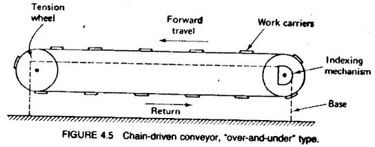
Figure.6.16. Chain Drive Conveyor System
Rotary transfer mechanisms
There are many strategies we want to index a circular table or dial at varied equal angular positions appreciate digital computer locations. Those delineated below are meant to be a representative instead of a whole listing.
RACK AND PINION: This mechanism is easy however isn't thought-about particularly suited to the high-speed operation usually related to categorization machines. The device is pictured in Figure.6.17. and uses a piston to drive the rack, which causes the pinion gear and connected categorization table to rotate. A clutch or alternative device is employed to produce rotation within the desired direction.
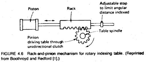
Figure.6.17. Rack and Pinion
RATCHET AND PAWL: This drive mechanism is shown in Figure.6.18. Its operation is simple but somewhat unreliable, owing to the wear and sticking of several of the components.
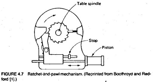
Figure.6.18. Ratchet and Pawl
Key Takeaways:
Methods of work part transport, Linear transfer mechanisms, rotary transfer mechanisms.
Automated Assembly Systems Assembly involves the change of integrity along with 2 or a lot of separate elements to create a new entity which can be assembly or subassembly. machine-controlled assembly refers to the utilization of mechanized and automatic devices to perform the varied functions in an associate degree production line or cell. machine-controlled assembly system performs a sequence of machine-controlled operations to mix multiple elements into one entity which may be a final product or sub-assembly. machine-controlled assembly technology ought to be thought-about once the subsequent condition exists.
High product demand and Stable product design: The assembly consists of no quite a restricted variety of elements. the merchandise is meant for machine-controlled assembly. machine-controlled assembly system involves less investment compared to transfer lines as a result of 1. Work half created is smaller in size compared to transfer lines. 2. Assembly operations don't have big mechanical forces and power demand.
TYPES OF AUTOMATED ASSEMBLY SYSTEMS
Based on the type of work transfer system that is used in the assembly system:
• Continuous transfer system
• Synchronous transfer system
• Asynchronous transfer system
• Stationary base part system
The first three types involve the same methods of work part transport described in the automated flow line. In the stationary base part system, the base part to which the other components are added is placed in a fixed location, where it remains during the assembly work.
Based on physical configuration:
• Dial-type assembly machine
• In-line assembly machine
• Carousel assembly system
• Single-station assembly machine
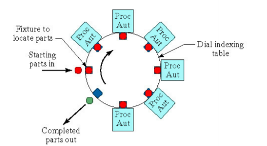
In the dial-type machine, the base part is indexed around a circular table or dial. The workstations are stationary and usually located around the outside periphery of the dial. The parts ride on the rotating table and arc registered or positioned, in turn, at each station a new component is added to the base part. This type of equipment is often referred to as an indexing machine or dial index machine and the configuration is shown in Figure 1 and an example of six station rotary shown in the figure.
Figure.6.19. Dial Type Machine
In-line type configuration
The in-line configuration assembly system consists of a sequence of workstations in a more-or-less straight-line arrangement as shown in the figure. An example of an in-line transfer machine used for metal-cutting operations is illustrated in Figure. The in-line assembly machine consists of a series of automatic workstations located along with an in-line transfer system. It is the automated version of the manual assembly line. Continuous, synchronous, or asynchronous transfer systems can be used with the in-line configuration.
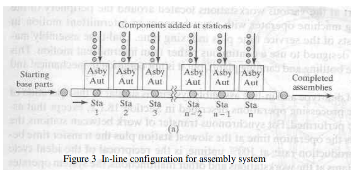
Figure.6.20. In-Line Configuration
Assembly line balancing Buffer Storages
An automated transfer line has consisted of several workstations which are linked together by a material handling system where parts are transferred from one station to the next
Buffer Storage

Figure.6.21. Buffer Storage
Automated assembly line for car manufacturing
Car producing robots offer automotive corporations a competitive advantage. They improve quality and cut back warrant costs; increase capability and relieve bottlenecks; and defend staff from dirty, troublesome, and dangerous jobs. automobile assembly plants use robots completely for spot fastening and painting, however, there are several alternative opportunities to use robots throughout the availability chain. OEMs, Tier 1s, and alternative half producers all stand to realize from victimization robots within the automobile producing trade.
Car factory robots cut back part-to-part variability. extremely repeatable, they ne'er tire or get distracted, therefore each cycle is performed similarly. Neither do they drop elements or handle them in a very manner that causes harm. That reduces waste antecedent caused by human error, which conjointly suggests that less variability in automobile assembly. Equipped with vision systems, automotive robots even will observe variation in incoming materials and adapt their programmed ways to suit. This, in turn, interprets to higher client satisfaction, fewer mistakes, and lower warrant prices.
Example: Contemplate the assembly of a car: assume that sure steps within the production line are to put in the engine, install the hood, and install the wheels (in that order, with discretionary opening steps); just one of those steps are often done at a time. In ancient production, just one automobile would be assembled at a time. If engine installation takes twenty minutes, hood installation takes 5 minutes, and wheels installation takes ten minutes, then an automobile is often made each thirty-five minutes. In the associate production line, automobile assembly is split between many stations, all operating at the same time. once a station is finished with an automobile, it passes it on to subsequent. By having 3 stations, 3 cars are often operated on at a similar time, every at a distinct stage of assembly. After finishing its work on the primary automobile, the engine installation crew will begin functioning on the second automobile. whereas the engine installation crew works on the second automobile, the primary automobile is often moved to the hood station and fitted with a hood, then to the wheels station and be fitted with wheels. once the engine has been put in on the second automobile, the second automobile moves to the hood assembly. At a similar time, the third automobile moves to the engine assembly. once the third car's engine has been mounted, it then is often moved to the hood station; meantime, subsequent cars (if any) are often moved to the engine installation station. Assuming no loss of your time once moving an automobile from one station to a different, the longest stage on the production line determines the output (20 minutes for the engine installation) therefore an automobile are often made each twenty minutes, once the primary automobile taking thirty-five minutes have been made.
Artificial intelligence in automation
Combining Automation and AI
When robotic method automation is combined with parts of AI like machine learning, the result's called intelligent method automation (IPA). Associate in Nursing IPA tool as powerful as a result of it permits US to reap each the advantages of automation inflated speed, efficiency, time-savings, and skill to scale with the insights, flexibility, and process power of AI. Marketers UN agency use IPA area unit ready to augment their capabilities, whereas off-loading repetitive campaign management tasks to the machine. This will be totally different from pure robotic automation therein the AI can begin, stop, or maybe alter what it's doing supported the atmosphere within which it operates. What’s a lot of, as a result of the most effective AI systems permit marketers to line guardrails, there’s no probability of unforeseen events taking outcomes too so much wide.
Key Takeaways:
Automated assembly line, types of automated assembly systems, automated assembly line for car manufacturing, artificial intelligence in automation.
Reference Books:
2. Bevan T, “Theory of Machines”, Third Edition, Longman Publication |
|
3. Paul E. Sandin, “Robot Mechanisms and Mechanical Devices Illustrated”, Tata McGraw Hill Publication
|
4. Ghosh Malik, “Theory of Mechanism and Machines”, East-West Pvt. Ltd.
|
5. M.P. Groover, “Automation, production systems, and computer-integrated manufacturing”, Prentice-Hall of India Pvt. Ltd
