Unit – 1
Casting Process
The primary metal castings were created throughout the amount from 4000 to three000 B.C., exploitation stone and metal molds for casting copper. Varied casting processes are developed over time, every with its own characteristics and applications, to fulfill specific style necessities. An outsized form of components and elements are created by casting, cherish engine blocks, crankshafts, automotive elements and powertrains, agricultural and railroad instrumentality, pipes and plumbing fixtures, power-tool housings, gun barrels, cookery pans, jewelry, medical science implants, and extremely massive elements for hydraulic turbines. 2 trends have had a significant impact on the casting trade. The primary is that the mechanization and automation of the casting method, that has LED to vital changes within the use of apparatus and labor. Advanced machinery and automatic process-control systems have replaced ancient ways of casting. The second major trend has been the increasing demand for high-quality castings with shut dimensional tolerances. These classifications are involving mould materials, pattern production, molding processes, and ways of feeding the mold with liquified metal. The key classes are as follows:
The pattern is the replica of the device which is the output of the casting process. This when molded in sand forms mold. After filling the mold with the molten metal there is a formation of casting. Patterns play a very important role in casting as they decide the quality as well as perfection in a particular casting process. Gates and runners are the most important components in several types of patterns. The pattern is the basic requirement for the creation of mold and it is always bigger than the size of the casting. There should be a proper selection of patterns so it must be able to sustain rough handling. It forms a mold cavity for casting processes. The patterns may be made of metals like aluminum, brass, plaster, and wax.
1.2.1 Patterns Materials:
There are some of the features of the best pattern material used for designing:
• Water resistant: The material used should be water resistance so it cannot be trusted easily.
• Cheap in cost and have very less weight: It should be cheap and of lightweight. So the cost of making patter is economical.
• Long lasting and hard: It should be hard and must have a long life. The long life of the material allows the pattern to be used for years.
• Industry oriented patterns are mostly designed simple and they are repairable.
During patterning processes, to handle any structural problems different allowances are made. These allowances include shrinkage allowances, shake allowances, Draft allowances and finally distortion allowances.
Following are some of the key factors that decide the types of patterns of casting you must choose:
• Features of the particular casting process,
• Number of castings that are to be created and
• Physical specifications, means size of casting.
1.2.2 Types of Patterns:
The various kinds of patterns that we use in casting process are
1. Single piece pattern is the cheapest pattern among all other types of pattern. This pattern generally used in simple processes. It is applied in small scale production. It is often used for the generation of large castings such as stuffing box of steam engine and for creating simple shapes, flat surfaces like simple rectangular blocks. The important characteristic of this pattern is that there is no need of joint in the mold area. In this pattern one surface is considered as flat portion. This flat surface is used for parting plane. Sand tools are used to cut the sand which ultimately make gating system. The molding becomes a difficult task if there is absence of this flat surface. It is expected to lie in cope or drag.

2. Two- Piece Pattern
Two- piece pattern is also called as split piece pattern. It is the popularly used for intricate castings. The shape of casting decides the exact place of parting plane. This parting plane may be flat or irregular surface. In two- piece pattern half part is always molded in drag and other half part is molded in cope. The cope part of the pattern has dowel pins. These dowel pins are used to align the two halves of split piece pattern. Holes in the drag half of the two- piece pattern matches exactly with dowel pins. It is used in applications where it is very difficult to withdraw casting from the mold. Two- piece patterns are used where the depth of casting is very high.

3. Multi Piece Pattern
Sometimes castings have very difficult and complicated designs. In such difficult situations multi piece types of patterns are used. 3 or more patterns are included in multi piece pattern. For instance, if we consider three- piece pattern which comes under multi piece pattern. This three- piece pattern consists of top, bottom and middle parts. The bottom part is drag, top part is cope where the middle part is termed as check box.
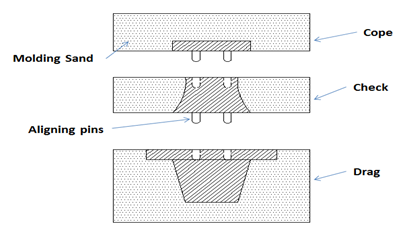
4. Match Plate Pattern
Basically Match plate pattern is a split pattern. Cope and drag areas are on the opposite faces of metallic plate. This metallic plate is termed as Match Plate. This type of pattern requires very less hard work and gives very high output. Because the gates and runners are also on the match plate. This is used in various manufacturing industries. This is very expensive and gives accuracy as well as high yield. This pattern is widely used for casting metals like aluminium.
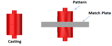
Applications:
1) Used in piston rings of I.C. engines
2) Multi piece pattern has wide scope in rotor hub.
5. Gated Pattern
Gated types of patterns are used to make multiple components inside the single mold. Gated pattern is nothing but the pattern consisting of one or more patterns. For joining different patterns gates are used. These are loose patterns where gates and runners have already attached. These patterns are very expensive. Due to their high cost they are used for creating small castings. These small castings further are used in molding machines as well as in mass producing processes.

The important advantage of this pattern is –
1) Low molding time
2) Molten metal is uniformly distributed
Applications:
Implemented usually in small castings such as corner bracket.
6. Skeleton Pattern
Skeleton pattern is used for castings which have simple size and shape. These castings are usually large in size. The only disadvantages of skeleton types of patterns are – it is applicable for small number of components and it is not cheap. Economically, it is not the best pattern. Stickler is used to remove extra sand. These are nothing but frames of wood that highlight the area which is to be cast. These patterns also help molder. They are widely used in process of pit or floor welding.
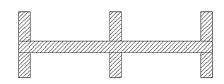
Applications:
1) Turbine manufacturing uses skeleton pattern
2) In daily applications such as water pipes are mostly designed with the help of skeleton pattern.
7. Sweep Pattern
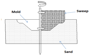
In sweep pattern we make use of wooden board. This wooden board of proper size is to be rotated about one edge to shape the cavity as circular or rotational symmetry. Sweep pattern is often used when we have to create casting in very short interval of time. Molds of extensive symmetrical casting can be made easily with the help of sweep pattern. Sweep pattern consists of three parts spindles, base and sweep which is wooden board. Spindle is directed in vertical direction and base is attached with sand
.
Applications:
Circular discs, wheels, large kettles are produces by making use of sweep pattern.
8. Loose Piece Pattern
It is very difficult to remove one piece of solid pattern which is above or below the parting plane having projections from the mold. With the help of loose piece types of patterns projections can be made by loose pieces. It requires skilled labor work as well as it is very expensive. There is one disadvantage of this loose piece pattern is that their shifting can be done due to ramming process.
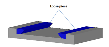
Applications:
1) In the production of axle pin.
2) Loose piece pattern is used in the rotor hub
9. Cope and Drag Pattern
Cope and drag pattern is a split pattern. This pattern has cope and drag on separate plate. Cope and drag pattern has two parts which are separately molded on molding box. After molding parts, these two separate parts are combined to form the entire cavity. Cope and drag pattern is almost like two-piece pattern.
This pattern types are used in the production of large castings where the molds are very heavy and unhandy for a user.
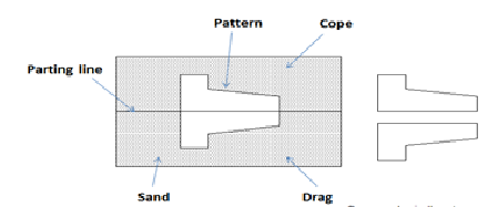
Applications:
1) This pattern is used in building flange pipe.
2) Cope and drag pattern is used in water jacket which is an important component of JCB.
10. Follow Board Pattern
Follow board pattern consists of tool that is a simple wooden board which is used for several reasons. The wooden board is used as a base in follow board pattern for molding process. This pattern is used in processes where casting structures are weak and they may break after the application of force.
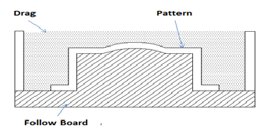
Applications:
This pattern is used for casting master pattern for many purposes.
11. Segmental Pattern
It is just a similar to that of a sweep pattern. The working structure of segmental pattern and sweep pattern is almost similar. For designing require shape or structure of mold they both employ a part of pattern. As the name suggest segmental pattern is in the form of segments and used for molding circular or round structures. In sweep pattern there is complete rotation but in segmental pattern there is no complete rotation. For creating mold, we can rotate partly to get required output.
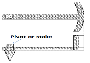
Applications:
The segmental pattern is used for constructing circular structures like wheels, rims, pulleys, etc.
12. Shell Pattern
Shell pattern is specially used for obtaining hollow shaped structure. Along the center the parting process is done. The resultant halves produced after parting are both doweled.
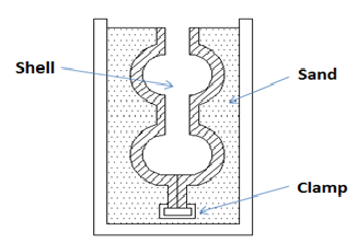
In casting, the above-mentioned patterns play crucial role. So we have to decide which pattern we should use according to requirements. This is all about the different types of patterns in the casting process. If you like this article then don’t forget to share it for others.
1.2.3 Pattern Allowance:
Pattern allowance is a vital feature as it affects the dimensional characteristics of the casting. Thus, when the pattern is produced, certain allowances must be given on the sizes specified in the finished component drawing so that a casting with the particular specification can be made. The selection of correct allowances greatly helps to reduce machining costs and avoid rejections. The allowances usually considered on patterns and core boxes are as follows:
All most all cast metals shrink or contract volumetrically on cooling. The metal shrinkage is of two types:
Liquid Shrinkage: It refers to the reduction in volume when the metal changes from liquid state to solid state at the solidus temperature. To account for this shrinkage; riser, which feed the liquid metal to the casting, are provided in the mold.
Solid Shrinkage: it refers to the reduction in volume caused when metal loses temperature in solid state. To account for this, shrinkage allowance is provided on the patterns. The rate of contraction with temperature is dependent on the material.
2. Draft or Taper Allowance
By draft is meant the taper provided by the pattern maker on all vertical surfaces of the pattern so that it can be removed from the sand without tearing away the sides of the sand mold and without excessive rapping by the molder.
Draft allowance varies with the complexity of the sand job. But in general inner details of the pattern require higher draft than outer surfaces. The amount of draft depends upon the length of the vertical side of the pattern to be extracted; the intricacy of the pattern; the method of molding; and pattern material.
3. Machining or Finish Allowance
The finish and accuracy achieved in sand casting are generally poor and therefore when the casting is functionally required to be of good surface finish or dimensionally accurate, it is generally achieved by subsequent machining. Machining or finish allowances are therefore added in the pattern dimension. The amount of machining allowance to be provided for is affected by the method of molding and casting used viz. hand molding or machine molding, sand casting or metal mold casting.
The amount of machining allowance is also affected by the size and shape of the casting; the casting orientation; the metal; and the degree of accuracy and finish required.
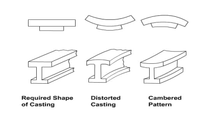
4. Distortion or Camber Allowance
Sometimes castings get distorted, during solidification, due to their typical shape. For example, if the casting has the form of the letter U, V, T, or L etc. it will tend to contract at the closed end causing the vertical legs to look slightly inclined. This can be prevented by making the legs of the U, V, T, or L shaped pattern converge slightly (inward) so that the casting after distortion will have its sides vertical.
The distortion in casting may occur due to internal stresses. These internal stresses are caused on account of unequal cooling of different section of the casting and hindered contraction. Measure taken to prevent the distortion in casting include:
5. Rapping Allowance
Before the withdrawal from the sand mold, the pattern is rapped all around the vertical faces to enlarge the mold cavity slightly, which facilitate its removal. Since it enlarges the final casting made, it is desirable that the original pattern dimension should be reduced to account for this increase. There is no sure way of quantifying this allowance, since it is highly dependent on the foundry personnel practice involved. It is a negative allowance and is to be applied only to those dimensions that are parallel to the parting plane.
Types of Moulding Sand:
According to the use, moulding sand may be classified as below:
1. Green Sand:
The green sand is the natural sand containing sufficient moisture in it. It is mixture of silica and 15 to 30% clay with about 8% water. Clay and water act as a bonding material to give strength. Molds made from this sand are known as green sand mould. The green sand is used only for simple and rough casting products. It is used for both ferrous and non-ferrous metals.
2. Dry Sand
When the moisture is removed from green sand, it is known as dry sand. The mould produced by dry sand has greater strength, rigidity and thermal stability. This sand is used for large and heavy castings.
3. Loam Sand
Loam sand is a mixture of 50 percent sand and 50 percent clay. Water is added in sufficient amount. It is used for large and heavy moulds e.g., turbine parts, hoppers etc.
4. Facing Sand:
A sand used for facing of the mould is known as facing sand. It consists of silica sand and clay, without addition of used sand. It is used directly next to the surface of the pattern. Facing sand comes in direct contact with the hot molten metal; therefore it must have high refractoriness and strength. It has very fine grains.
5. Parting Sand:
Pure silica sand employed on the faces of the pattern before moulding is known as parting sand. When the pattern is withdrawn from the mould, the moulding sand sticks to it. To avoid sticking, parting sand is sprinkled on the pattern before it is embedded in the moulding sand. Parting sand is also sprinkled on the contact surface of cope, drag and cheek.
6. Backing or Floor Sand
The backing sand is old and repeatedly used sand of black colour. It is used to back up the facing sand and to fill the whole volume of the box. This sand is accumulated on the floor after casting and hence also known as floor sand.
7. System Sand:
The sand employed in mechanical heavy castings and has high strength, permeability and refractoriness, is known as system sand. It is used for machine moulding to fill the whole flask. In machine moulding no facing sand is used. The system sand is cleaned and has special additives.
8. Core Sand:
A sand used for making cores is known as core sand. It is silica sand mixed with core oil (linseed oil, resin, mineral oil) and other binding materials (dextrine, corn flour, sodium silicate). It has remarkable compressive strength.
9. Molasses Sand:
A sand which carries molasses as a binder is known as molasses sand. It is used for core making and small castings of intricate shapes.
1.3.1 Properties of Moulding Sand
Following are the important properties of moulding sand:
1. Porosity:
Porosity also known as permeability is the most important property of the moulding sand. It is the ability of the moulding sand to allow gasses to pass through. Gasses and steam are generated during the pouring of molten metal into the sand cavity. This property depends not only on the shape and size of the particles of the sand but also on the amount of the clay, binding material, and moisture contents in the mixture.
2. Cohesiveness:
Cohesiveness is the property of sand to hold its particles together. It may be defined as the strength of the moulding sand. This property plays a vital role in retaining intricate shapes of the mould.
Insufficient strength may lead to a collapse in the mould particles during handling, turning over, or closing. Clay and bentonite improve the cohesiveness.
3. Adhesiveness:
Adhesiveness is the property of sand due to which the sand particles stick to the sides of the moulding box. Adhesiveness of sand enables the proper lifting of cope along with the sand
4. Plasticity:
Plasticity is the property of the moulding sand by virtue of which it flows to all corners around the mould when rammed, thus not providing any possibility of left out spaces, and acquires a predetermined shape under ramming pressure.
5. Flow-Ability:
Flow-ability is the ability of moulding sand to free flow and fill the recesses and the fine details in the pattern. It varies with moisture content.
6. Collapsibility:
Collapsibility is the property of sand due to which the sand mould collapse automatically after the solidification of the casting. The mould should disintegrate into small particles of moulding sand with minimum force after the casting is removed from it.
7. Refractoriness:
Refractoriness is the property of sand to withstand high temperature of molten metal without fusion or soften.
Moulding sands with poor refractoriness may burn when the molten metal is poured into the mould. Usually, sand moulds should be able to withstand up to 1650°C.
1.3.2 Core making:
Core making is the process which forms the interior part of the casting. The mould provides a space for the molten metal to go, while the core keeps the metal from filling the entire space.
Cores are produced by blowing, ramming or in heated processes, investing sand into a core box. The finished cores, which can be solid or hollow, are inserted into the mould to provide the internal cavities of the casting before the mould halves are joined. Sand cores are also widely used in die-casting, where permanent metal moulds are employed.
The gases in metal are important in deciding the defect free castings. In metal castings,
gases may be mechanically trapped, generated due to variation in their solubility at
different temperatures and phases, generated because of chemical reaction.
Gases generally present are: hydrogen, nitrogen
Hydrogen: Based on the solubility of hydrogen, metals are divided as
Endothermic (metals like Al, Mg, Cu, Fe, Ni), Exothermic (like Ti, Zr)
The solubility of hydrogen in various metals are shown in figure. Here solubility S is the volume of H2 gas absorbed by 100 g. of metal. The solubility of hydrogen in solid and liquid phases (pressure = 1 atm) at solidus temperature is given in table.

 heat of solution of one mol of hydrogen; sign determines endothermic or exothermic
Metal | Liquid soubility | Solid solubility (cc kg) |
Fe | 270 | 70 |
Mg | 260 | 180 |
Cu | 55 | 20 |
Al | 7 | 0.4 |
A good gating design should ensure proper distribution of molten metal without excessive temperature loss, turbulence, gas entrapping and slags. If the molten metal is poured very slowly, since time taken to fill the mould cavity will become longer, solidification will start even before the mould is completely filled. This can be restricted by using super-heated metal, but in this case solubility will be a problem. If the molten metal is poured very faster, it can erode the mould cavity. So gating design is important and it depends on the metal and molten metal composition. For example, aluminium can get oxidized easily. Gating design is classified mainly into two (modified: three) types: Vertical gating, bottom gating, horizontal gating
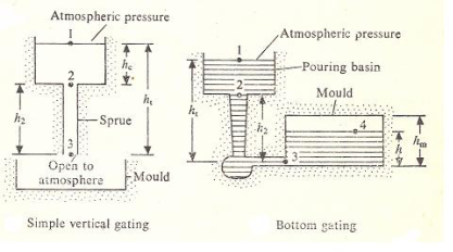
Vertical gating: the liquid metal is poured vertically, directly to fill the mould with atmospheric pressure at the base end.
Bottom gating: molten metal is poured from top, but filled from bottom to top. This minimizes oxidation and splashing while pouring.
Horizontal gating: is a modification of bottom gating, in which some horizontal portions are added for good distribution of molten metal and to avoid turbulence.
A) Vertical Gating:
For analysis we use energy balance equation like Bernoulli’s equation

Assuming  and level at 1 is maintained constant, so
  frictional losses are neglected.
The energy balance between point 1 and 3 gives,

Here  can be referred as velocity at the spruce base or say gate,
Continuity equation:
Volumetric flow rate, 
As the metal flows into the sprue opening, it increases in velocity and hence the cross-sectional area of the channel must be reduced.
Otherwise, as the velocity of the flowing molten metal increases toward the base of the sprue, air can be aspirated into the liquid and taken into the mould cavity.
To prevent this condition, the sprue is designed with a taper, so that the volume flow rate, Q = Av remains the same at the top and bottom of the sprue.
The mould filling time is given by,

Ag = cross-sectional area of gate; V = volume of mould
b) Bottom gating:

Apply Bernoulli’s equation between points and 3 and between 3 and 4 is equivalent to modifying  equation in the previous gating.
 where
where  is effective head
Between 3 and 4:
Assume
 is very small
All KE at 3 is lost after the liquid metal enters the mould
Assuming in the mould the height moves up by dh in a time ‘dt’;  and
and  are mould area and gate area, then

Combining above two equations, we get


The casting time for filling the mold cavity can be calculated according to the following equations:
 ………………..eq (I)
Wherein:
t = casting time in s
V = casting volume in m3
AA = gate area in m2
vA = flow rate in the gate in m/s.
For dimensions more typical in practice, the equation is as follows (with the mold filling time t being calculated in ms).
 …………….eq (II)
vA is based on eq. 1 so that the casting time according to eq. 3 is as follows:
 ……….eq (III)
When using the casting mass m for calculation instead of the casting volume, then V = m/ρl and the mold filling time t is:
 ………..eq (IV)
In practice, casting time diagrams and tables are often used for orientation, mainly established on the basis of the mean casting wall thickness and the alloy used.
Numerical: Two gating design for a mould of 50cm *25cm*15cm are as shown in fig the cross-sectional area of the gate is 5cm2. Determine the filling time for both the design.
Solution:
Time for top gating:
Ag = 5cm2
Am = 50*25 = 1250cm2
hm =15cm
ht =15cm

ttop= 21.8 sec.
Filling time for bottom gating:


Tbottom = 43.71 sec.
Hence, time taken to fill the casting from bottom gating is double the time taken to filled by the top gating system for same dimension.
TBottom = 2TTop.
As delineated earlier, a riser is employed in a very sand-casting mould to feed liquid metal to the casting throughout temperature reduction so as to catch up on curing shrinkage. To operate, the riser should stay liquefied till once the casting solidifies. Chvorinov’s rule is accustomed reckon the scale of a riser that may satisfy this demand.
To perform a casting operation, the metal should be heated to a temperature somewhat higher than its freezing point so poured into the mould cavity to solidify. During this section, we have a tendency to think about many aspects of those 2 steps in casting. Heating furnaces of assorted sorts are accustomed heat the metal to a liquefied temperature sufficient for casting. the warmth energy needed is that the sum of (1) the heat to boost the temperature to the freezing point, (2) the warmth of fusion to convert it from solid to liquid, and (3) the warmth to boost the liquefied metal to the required temperature for gushing. This will be expressed:

where H =heat content needed to boost the temperature of the metal to the gushing temperature;
 Density, g/cm3 (lbm/in3);
Cs = weight specific heat for the solid metal, J/g-C (Btu/lbm-F);
Tm = melting temperature of the metal, 0C (0F);
To =starting temperature - usually ambient, 0C (0F);
Hf=heat of fusion, J/g (Btu/lbm);
Cl = weight specific heat of the liquid metal, J/g-C (Btu/lbm-F);
Tp = pouring temperature, 0C(0F);
V = volume of metal being heated, cm3 (in3).
Pouring the Molten Metal:
Once heating, the metal is prepared for gushing. Introduction of liquefied metal into the mould, as well as its flow through the gating system and into the cavity could be an essential step within the casting method. For this step to achieve success, the metal should flow into all regions of the mould before curing. Factors moving the gushing operation embody pouring temperature, gushing rate, and turbulence. The gushing temperature is that the temperature of the liquefied metal because it is introduced into the mould. What’s vital here is that the distinction between the temperature at gushing and also the temperature at that temperature reduction begins (the freezing point for a pure metal or the liquidus temperature for alloy). This temperature distinction is usually observed because the superheat. This term is additionally used for the number of warmth that has to be off from the liquefied metal between gushing and once curing commences.
Gushing rate refers to the meter rate at that the liquified metal is poured into the mould. If the speed is simply too slow, the metal can chill and freeze before filling the cavity. If the gushing rate is excessive, turbulence will become a significant drawback. Turbulence in fluid flow is characterized by erratic variations within the magnitude and direction of the rate throughout the fluid. The flow is agitated and irregular instead of swish and efficient, as in streamline flow. flow ought to be avoided throughout gushing for many reasons. It tends to accelerate the formation of metal oxides which will become entrapped throughout curing, so degrading the standard of the casting. Turbulence conjointly aggravates mould erosion, the gradual eroding of the mould surfaces because of impact of the flowing liquefied metal. The densities of most liquefied metals are a lot of above water and alternative fluids we have a tendency to usually affect. These liquefied metals also are rather more with chemicals reactive than at temperature. Consequently, the damage caused by the flow of those metals within the mould is important, particularly beneath turbulent conditions. Erosion is very serious once it happens within the main cavity as a result of the pure mathematics of the forged part is affected.
Engineering Analysis of Pouring:
There are many relationships that govern the flow of liquid metal through the gating system and into the mould. A very important relationship is Bernoulli’s theorem that states that the additions of the energies (head, pressure, kinetic, and friction) at any 2 points in a very flowing liquid are equal. This will be written within the following form:

where h = head, cm (in); p = pressure on the liquid, N=cm2(lb/ in2);  = density, g/cm3 (lbm/in3); v = flow velocity; cm/s (in/sec); g = gravitational acceleration constant,981 cm/s/s (32.2×12 = 386 in/sec/sec); and F = head losses due to friction, cm (in). Subscripts1 and 2 indicate any two locations in the liquid flow.
Bernoulli’s equation is simplified in many ways that. If we have a tendency to ignore friction losses (to take care, friction can have an effect on the liquid flow through a sand mold), and assume that the system remains at gas pressure throughout, then the equation is reduced to

This can be accustomed confirm the rate of the liquefied metal at the bottom of the tropical sprue. Allow us to outline purpose one at the highest of the tropical sprue and point two at its base. If purpose two is employed because the reference plane, then the pinnacle at that time is zero (h2 = 0) and h1 is that the height (length) of the tropical sprue. Once the metal is poured into the gushing cup and overflows down the tropical sprue, its initial speed at the highest is zero (v1 = 0). Hence, Eq. more simplifies to

which is resolved for the flow velocity:

where v = the velocity of the liquid metal at the base of the sprue, cm/s (in/sec);
g = 981 cm/s/s (386 in/sec/sec); and h = the height of the sprue, cm (in).
Another relationship of importance throughout gushing is that the continuity law, that states that the quantity rate of flow remains constant throughout the liquid. the quantity flow is up to the rate increased by the cross-sectional space of the flowing liquid. The continuity law is expressed:

where Q = volumetric flow rate, cm3/s (in3/sec); v =velocity as before;
A = cross-sectional area of the liquid, cm2 (in2); and also, the subscripts check with any 2 points within the flow system. Thus, a rise in space leads to a decrease in speed, and contrariwise.
Above equations indicate that the tropical sprue ought to be tapered. Because the metal accelerates throughout its descent into the tropical sprue gap, the cross-sectional space of the channel should be reduced; otherwise, because the speed of the flowing metal will increase toward the bottom of the tropical sprue, air is aspirated into the liquid and conducted into the mould cavity. to forestall this condition, the tropical sprue is meant with a taper, in order that the quantity flow vA is that the same at the highest and bottom of the tropical sprue. Presumptuous that the runner from the tropical sprue base to the mould cavity is horizontal (and thus the pinnacle h is that the same as at the sprue base), then the quantity rate of flow through the gate and into the mould cavity remains up to vA at the bottom. Consequently, we are able to estimate the time needed to fill a mould cavity of volume V as

Where TMF = mold filling time, s (sec); V = volume of mold cavity, cm3 (in3); and Q = volume flow rate, as before. The mold filling time computed by Eq. must be considered a minimum time. this is often as a result of the analysis ignores friction losses and potential constriction of flow within the gating system; so, the mould filling time are going to be longer than what's given by above Eq.
Solidification of Metals:
Once gushing into the mould, the liquefied metal cools and solidifies. During this section we have a tendency to examine the physical mechanism of curing that happens throughout casting. Problems related to curing embody the time for a metal to freeze, shrinkage, directional curing, and riser style. Curing involves the transformation of the liquefied metal into the solid state. The curing process differs looking on whether or not the metal could be a pure part or alloy.
Pure Metals: A pure metal solidifies at a relentless temperature up to its temperature that is that the same as its melting point. The melting points of pure metals are standard and documented. The particular temperature reduction takes time, known as the native curing time in casting, throughout that the metal’s heat of transformation of fusion is discharged into the encompassing mould. The whole curing time is that the time taken between gushing and complete curing.
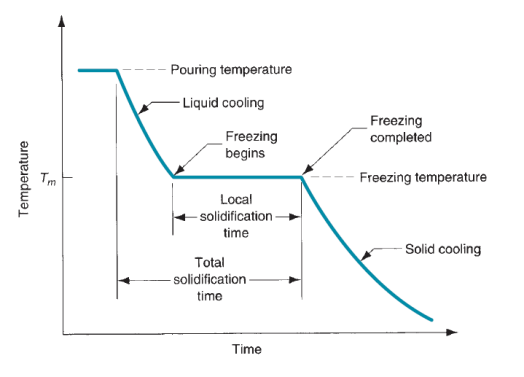
Figure: Cooling curve for a pure metal during casting.
Once the casting has utterly solid, cooling continues at a rate indicated by the downward slope of the cooling curve. as a result of the chilling action of the mould wall, a skinny skin of solid metal is at first fashioned at the interface like a shot once gushing. Thickness of the skin will increase to make a shell round the liquefied metal as curing progresses inward toward the middle of the cavity. The speed at that temperature reduction payoff depends on heat transfer into the mould, moreover because the thermal properties of the metal. It’s of interest to look at the aluminiferous grain formation and growth throughout this curing process. The metal that forms the initial skin has been chop-chop cooled by the extraction of warmth through the mould wall. This cooling action causes the grains within the skin to be fine and indiscriminately destined. As cooling continues, more grain formation and growth occur in a very direction removed from the warmth transfer. Since the warmth transfer is thru the skin and mould wall, the grains grow inside as needles or spines of solid metal. As these spines enlarge, lateral branches type, and as these branches grow, more branches type at right angles to the primary branches. this sort of grain growth is observed as nerve fiber growth, and it happens not solely within the temperature reduction of pure metals however alloys moreover. These dendroidal structures are bit by bit filled-in throughout temperature reduction, as further metal is frequently deposited onto the dendrites till complete curing has occurred. The grains ensuing from this nerve fibre growth combat a most popular orientation, tending to be coarse, columnar grains aligned toward the middle of the casting.
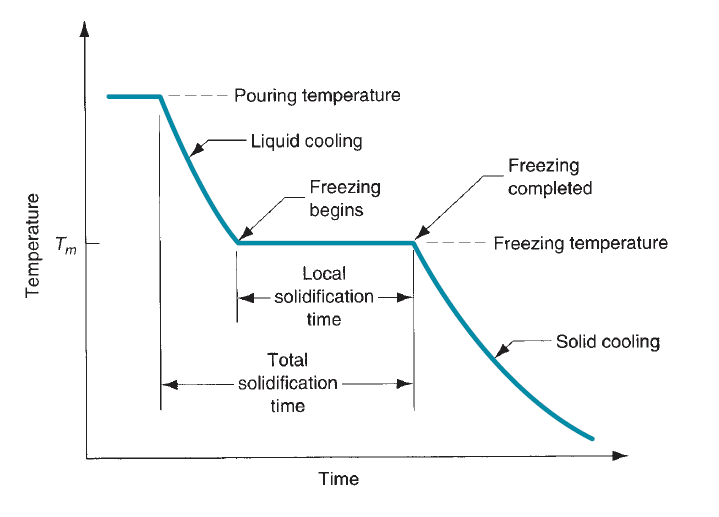
Figure: Characteristic grain structure in a casting of a pure metal, showing randomly oriented grains of small size near the mold wall, and large columnar grains oriented toward the center of the casting.
Most Alloys: Most alloys freeze over a temperature vary instead of at one temperature. The precise vary depends on the alloy system and also the specific composition.
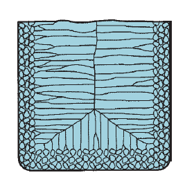
Figure: (a) Phase diagram for a copper– nickel alloy system and (b) associated cooling curve for a 50%Ni–50%Cu composition during casting.
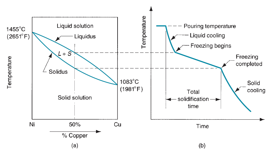
Figure: Characteristic grain structure in an alloy casting, showing segregation of alloying components in the center of casting.
Curing of alloy is explained with relevance figure that shows the part diagram for a specific alloy system and also the cooling curve for a given composition. As temperature drops, temperature reduction begin at the temperature indicated by the liquidus and is completed once the solidus is reached. The beginning of temperature reduction is comparable to it of the pure metal. A skinny skin is made at the mould wall because of the big gradient at this surface. Temperature reduction then progresses as before through the formation of dendrites that grow removed from the walls. However, attributable to the temperature unfold between the liquidus and solidus, the character of the nerve fiber growth is such Associate in Nursing advancing zone is made during which each liquid and solid metal exist. The solid parts are the nerve fiber structures that have fashioned sufficiently to entice little islands of liquid metal within the matrix. This solid–liquid region encompasses a soft consistency that has impelled its name because the mushy zone. Looking on the conditions of temperature reduction, the mushy zone is comparatively slender, or it will exist throughout, most of the casting. The latter condition is promoted by factors cherish slow heat transfer out of the new metal and a large distinction between liquidus and solidus temperatures. Gradually, the liquid islands within the nerve fiber matrix solidify because the temperature of the casting drops to the solidus for the given alloy composition.
Directional solidification (DS) and progressive solidification are types of solidification within castings. Directional solidification is solidification that occurs from farthest end of the casting and works its way towards the sprue. Progressive solidification, also known as parallel solidification, is solidification that starts at the walls of the casting and progresses perpendicularly from that surface.


Progressive solidification
As material is changed from liquid to solid state, most metals and alloys shrink. When liquid content is thus not sufficient to compensate for this shrinkage, a deficiency in shrinking forms may develop. As gradual solidification replaces directional solidification, a deficiency in shrinkage is created.

The mold cavity's geometrical form influences progressive and lateral solidification. Differently heat streaming happens at the end of tunnel-type geometries, which enable the casting region to cool faster than the surrounding areas. Because there is less heat flow, large cavities are not cooling as rapidly as the surroundings, this is called a rising effect. Remember also that corners may produce separate or convergent heat-flow areas (often called hot spots).[4] Chills, rise-ups, isolating sleeves, regulation of the flow rate and flow temperature may also be employed in order to induce directional solidification.
The washing method can be used with directional solidification. Since most contaminations will be more soluble in liquid than in solids during solidification, they "push" impurities through the solidification front, which leads to a lower concentration of impurities for many of the finished casting than the feedstock, and to the impurities for enrichment of the last solidified metal. It can be replaced and reused for this last portion of steel. The appropriateness for directional solidification to remove certain impurities from certain metals depends, as described in the Scheil equation, on the partition coefficient for the impurity in that metal. Driven solidification (zone melting) is frequently used in the production of multi crystalline silicone for solar cells as a purification step.
Cleaning and finishing operations in foundries have become more and more complex due to the increasing variety of impurities. Because of this, greater emphasis is now being placed in the field of metal cleaning and finishing. A wide range of machines and equipment have been developed that make the process of metal cleaning and finishing easier. The various types of equipment used for cleaning and finishing of metals in foundries serve different purposes, such as cutting, buffing, sealing, grinding, blast cleaning, vibratory cleaning, abrasion, and more. Cleaning and finishing of castings are integral to every foundry's operation. The type of castings including shape, size, weight, and the production rate, are all crucial factors in selecting a suitable blast cleaning equipment, however, these are not the only considerations. With various molding processes creating thousands of casting types and configurations, there are a large number of arrangements for cooling, sand shakeout, and degating. All of these upstream activities determine the cleaning requirement. Succeeding operations, such as the final use of the casting, may also play a part in the selection process of blast arrangement.
Types
Some of the important types of cleaning & finishing equipment are -
|
|
These cleaning and finishing equipment are used to remove molding materials, risers, fins, ingates and other excess surface metal. These have also found to be useful in clearing holes or passageways; and in removing fused and penetrated sand defects to develop castings for finishing. Cleaning starts at shakeout and precedes finishing tasks. Consumable materials, such as - saw blades, cutting and grinding wheels, abrasive and nonabrasive cleaning systems, and shot & grit have proved to be essential for cleaning and finishing operations.
Advantages
Due to improved equipment, the process of cleaning and finishing of castings has become much easier and simpler. Separating castings from sand molds is now easier and this results in superior quality castings and increased productivity.
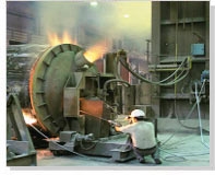
Shakeout processes comprise separation of molds and sand from flasks, castings from sand, cores from castings, and even shot from shot blasted castings.
Varied defects will develop throughout producing that rely on factors cherish materials, half style, and process techniques. Whereas some defects have an effect on solely the looks of the components created, others will have major adverse effects on the structural integrity of the components. Many defects will develop in castings. As a result of totally different names are utilized in the past to explain an equivalent defect, the International Committee of metalworks Technical Associations has developed an identical word consisting of seven basic classes of casting defects, known with boldface capital letters:
A-Metallic projections, consisting of fins, flash, or projections cherish swells and rough surfaces.
B-Cavities, consisting of rounded or rough internal or exposed cavities as well as blowholes, pinholes, and shrinkage cavities.
C-Discontinuities cherish cracks, cold or hot tearing, and cold shuts. If the curing metal is unnatural from shrinking freely, cracking and tearing might occur. Though many factors are concerned in tearing, coarse grain size and also the presence of low-melting-point segregates on the grain boundaries (inter granular) increase the tendency for warm tearing. Cold shut is interface in a very casting that lacks complete fusion as a result of the meeting of 2 streams of liquid metal from totally different gates.
D-Defective surface, cherish surface folds, laps, scars, adhering sand layers, and compound scale.
E-Incomplete casting, cherish misruns (due to premature solidification), lean volume of the metal poured, and run out (due to loss of metal from the mould once pouring). Incomplete castings can also result from the liquefied metal being at too low a temperature or from pouring the metal too slowly.
F-Incorrect dimensions or shape, because of factors cherish improper shrinkage allowance, pattern-mounting error, irregular contraction, malformed pattern, or crooked casting.
G-Inclusions, that type throughout melting, solidification, and molding; these are typically nonmetal. They’re considered harmful as a result of they act as stress raisers and so cut back the strength of the casting. Inclusions might type throughout melting once the liquefied metal reacts with the atmosphere (usually oxygen) or with the vessel or mould material. Chemical reactions among elements within the liquefied metal itself might manufacture inclusions; slags and alternative foreign material entrapped in the molten metal conjointly become inclusions, though filtering will take away particles as little as thirty um. Finally, spilling of the mould and core surfaces will manufacture inclusions, so indicating the importance of the standard of molds and of their maintenance.
Residual Stresses:
“Internal” or “residual”, regardless of however we have a tendency to outline them, in a very metal material such stresses continually derive from some irregularity conditions within the fabric, irregularity that in castings is mostly including the very fact that the casting cooling doesn't occur at the same time altogether points, since the inner surface cools quicker than the fabric core, and also the zones with refined walls before the massive components. Generally terms “the residual stresses are generated within the part once irregularity components are gift within the science or material method characteristics”. within the case of castings, aside from gross errors resulting in have homogeneity variations of the fabric among the varied zones of the half, the most supply of residual stresses is beyond any doubt the cooling method or, better, the non-simultaneous cooling among the varied zones of an equivalent part. Reminding of course that the particular volume of a metal material is directly proportional to temperature, it results that once the cooling of the external casting half happens, and internal half is implanted by high-temperature material.
Once the cooling extends to the fabric core, too, this may not shrink freely as a result of unnatural by the external solid surface: thus, we are going to have the external half stressed by compression by the core material, that in its flip are going to be stressed by traction by the external half. Analogue concerns are valid if the casting options components with totally different thickness, with components with refined stable walls before the parts with larger section, so the establishing of mutual traction or perhaps of deformations. we are able to thus state that the strain state in a very casting with refined walls has a minimum of 2 elements, one that we have a tendency to might outline “vertical” elicited by the interactions between the fabric on the surface and also the underlying material, and a “geometrical” one elicited by the constraints implanted by the encompassing material.
Permanent mold casting is a metal casting process that employs reusable molds ("permanent molds"), usually made from metal. The most common process uses gravity to fill the mold, however gas pressure or a vacuum are also used. A variation on the typical gravity casting process, called slush casting, produces hollow castings. Common casting metals are aluminium, magnesium, and copper alloys. Other materials include tin, zinc, and lead alloys and iron and steel are also cast in graphite molds.
Process
There are four main types of permanent mold casting: gravity, slush, low-pressure, and vacuum.
Gravity process
The gravity process begins by preheating the mold to 150–200 °C (300–400 °F) to ease the flow and reduce thermal damage to the casting. The mold cavity is then coated with a refractory material or a mold wash, which prevents the casting from sticking to the mold and prolongs the mold life. Any sand or metal cores are then installed and the mold is clamped shut. Molten metal is then poured into the mold. Soon after solidification the mold is opened and the casting removed to reduce chances of hot tears. The process is then started all over again, but preheating is not required because the heat from the previous casting is adequate and the refractory coating should last several castings. Because this process is usually carried out on large production run work-pieces automated equipment is used to coat the mold, pour the metal, and remove the casting.
The metal is poured at the lowest practical temperature in order to minimize cracks and porosity. The pouring temperature can range greatly depending on the casting material; for instance zinc alloys are poured at approximately 370 °C (698 °F), while Gray iron is poured at approximately 1,370 °C (2,500 °F).
Mold
Molds for the casting process consist of two halves. Casting molds are usually formed from gray cast iron because it has about the best thermal fatigue resistance, but other materials include steel, bronze, and graphite. These metals are chosen because of their resistance to erosion and thermal fatigue. They are usually not very complex because the mold offers no collapsibility to compensate for shrinkage. Instead the mold is opened as soon as the casting is solidified, which prevents hot tears. Cores can be used and are usually made from sand or metal.
As stated above, the mold is heated prior to the first casting cycle and then used continuously in order to maintain as uniform a temperature as possible during the cycles. This decreases thermal fatigue, facilitates metal flow, and helps control the cooling rate of the casting metal
Venting usually occurs through the slight crack between the two mold halves, but if this is not enough then very small vent holes are used. They are small enough to let the air escape but not the molten metal. A riser must also be included to compensate for shrinkage. This usually limits the yield to less than 60%.Mechanical ejectors in the form of pins are used when coatings are not enough to remove casts from the molds. These pins are placed throughout the mold and usually leave small round impressions on the casting. [citation needed]
Slush
Slush casting is a variant of permanent molding casting to create a hollow casting or hollow cast. In the process the material is poured into the mold and allowed to cool until a shell of material forms in the mold. The remaining liquid is then poured out to leave a hollow shell. The resulting casting has good surface detail but the wall thickness can vary. The process is usually used to cast ornamental products, such as candlesticks, lamp bases, and statuary, from low-melting-point materials. A similar technique is used to make hollow chocolate figures for Easter and Christmas.
Low-pressure
Schematic of the low-pressure permanent mold casting process
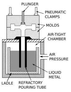
Low-pressure permanent mold (LPPM) casting uses a gas at low pressure, usually between 3 and 15 psi (20 to 100 kPa) to push the molten metal into the mold cavity. The pressure is applied to the top of the pool of liquid, which forces the molten metal up a refractory pouring tube and finally into the bottom of the mold. The pouring tube extends to the bottom of the ladle so that the material being pushed into the mold is exceptionally clean. No risers are required because the applied pressure forces molten metal in to compensate for shrinkage. Yields are usually greater than 85% because there is no riser and any metal in the pouring tube just falls back into the ladle for reuse.
The vast majority of LPPM casting are from aluminum and magnesium, but some are copper alloys. Advantages include very little turbulence when filling the mold because of the constant pressure, which minimizes gas porosity and dross formation. Mechanical properties are about 5% better than gravity permanent mold castings. The disadvantage is that cycles times are longer than gravity permanent mold castings.
Vacuum
Vacuum permanent mold casting retains all of the advantages of LPPM casting, plus the dissolved gases in the molten metal are minimized and molten metal cleanliness is even better. The process can handle thin-walled profiles and gives an excellent surface finish. Mechanical properties are usually 10 to 15% better than gravity permanent mold castings. The process is limited in weight to 0.2 to 5 kg (0.44 to 11.02 lb).
Advantages and disadvantages
The main advantages are the reusable mold, good surface finish, good dimensional accuracy, and high production rates. Typical tolerances are 0.4 mm for the first 25 mm (0.015 in for the first inch) and 0.02 mm for each additional centimeter (0.002 in per in); if the dimension crosses the parting line add an additional 0.25 mm (0.0098 in). Typical surface finishes are 2.5 to 7.5 μm (100–250 μin) RMS. A draft of 2 to 3° is required. Wall thicknesses are limited to 3 to 50 mm (0.12 to 1.97 in). Typical part sizes range from 100 g to 75 kg (several ounces to 150 lb). Other advantages include the ease of inducing directional solidification by changing the mold wall thickness or by heating or cooling portions of the mold. The fast cooling rates created by using a metal mold results in a finer grain structure than sand casting. Retractable metal cores can be used to create undercuts while maintaining a quick action mold.
There are three main disadvantages: high tooling cost, limited to low-melting-point metals, and short mold life. The high tooling costs make this process uneconomical for small production runs. When the process is used to cast steel or iron the mold life is extremely short. For lower melting point metals the mold life is longer but thermal fatigue and erosion usually limit the life to 10,000 to 120,000 cycles. The mold life is dependent on four factors: the mold material, the pouring temperature, the mold temperature, and the mold configuration. Molds made from gray cast iron can be more economical to produce but have short mold lives. On the other hand, molds made from H13 tool steel may have a mold life several times greater. The pouring temperature is dependent on the casting metal, but the higher the pouring temperature the shorter the mold life. A high pouring temperature can also induce shrinkage problems and create longer cycle times. If the mold temperature is too low misruns are produced, but if the mold temperature is too high then the cycle time is prolonged and mold erosion is increased. Large differences in section thickness in the mold or casting can decrease mold life as well
Investment casting is an industrial process based on lost-wax casting, one of the oldest known metal-forming techniques. The term "lost-wax casting" can also refer to modern investment casting processes.
Investment casting has been used in various forms for the last 5,000 years. In its earliest forms, beeswax was used to form patterns necessary for the casting process. Today, more advanced waxes, refractory materials and specialist alloys are typically used for making patterns. Investment casting is valued for its ability to produce components with accuracy, repeatability, versatility and integrity in a variety of metals and high-performance alloys.
The fragile wax patterns must withstand forces encountered during the mold making. Much of the wax used in investment casting can be reclaimed and reused. Lost-foam casting is a modern form of investment casting that eliminates certain steps in the process.
Water glass and silica sol investment casting are the two primary investment casting methods nowadays. The main differences are the surface roughness and cost of casting. Water glass method dewaxes into the high-temperature water, and the ceramic mold is made of water glass quartz sand. Silica sol method dewaxes into the flash fire, and silica sol zircon sand makes the ceramic mold. Silica sol method costs more but has the better surface than the water glass method.
The process can be used for both small castings of a few ounces and large castings weighing several hundred pounds. It can be more expensive than die casting or sand casting, but per-unit costs decrease with large volumes. Investment casting can produce complicated shapes that would be difficult or impossible with other casting methods. It can also produce products with exceptional surface qualities and low tolerances with minimal surface finishing or machining required.
Process
A wax pattern used to create a jet engine turbine blade
Castings can be made from an original wax model (the direct method) or from wax replicas of an original pattern that need not be made from wax (the indirect method). The following steps describe the indirect process, which can take two to seven days to complete.
Produce a master pattern: An artist or mould-maker creates an original pattern from wax, clay, wood, plastic, or another material.[5] In recent years the production of patterns using 3D printing has become popular using mainly resin based SLA or DLP printers for high resolution patterns or standard PLA filament when high levels of accuracy are not required. If using a 3D Printed pattern proceed directly to step 5.
Create a mould: A mould, known as the master die, is made to fit the master pattern. If the master pattern was made from steel, the master die can be cast directly from the pattern using metal with a lower melting point. Rubber moulds can also be cast directly from the master pattern. Alternatively, a master die can be machined independently—without creating a master pattern.
Produce wax patterns: Although called wax patterns, pattern materials may also include plastic and frozen mercury. Wax patterns can be produced in one of two ways. In one process, the wax is poured into the mold and swished around until an even coating, usually about 3 mm (0.12 in) thick, covers the inner surface of the mould. This is repeated until the desired pattern thickness is reached. Another method involves filling the entire mould with molten wax and letting it cool as a solid object. [citation needed]
If a core is required, there are two options: soluble wax or ceramic. Soluble wax cores are designed to melt out of the investment coating with the rest of the wax pattern; ceramic cores are removed after the product has hardened.
Assemble wax patterns: Multiple wax patterns can be created and assembled into one large pattern to be cast in one batch pour. In this situation, patterns are attached to a wax sprue to create a pattern cluster, or tree. To attach patterns, a heating tool is used to slightly melt designated wax surfaces, which are then pressed against each other and left to cool and harden. As many as several hundred patterns can be assembled into the tree. Wax patterns can also be chased, which means parting lines or flashings are rubbed out using the heated metal tool. Finally, patterns are dressed (by removing imperfections) to look like finished pieces.
Apply investment materials: The ceramic mould, known as the investment, is produced by repeating a series of steps—coating, stuccoing, and hardening—until a desired thickness is achieved. Coating involves dipping a pattern cluster into a slurry of fine refractory material and then draining to create a uniform surface coating. Fine materials are used in this first step, also called a prime coat, to preserve fine details from the mould. Stuccoing applies coarse ceramic particles by dipping patterns into a fluidised bed, placing it in a rainfall-sander, or by applying materials by hand. Hardening allows coatings to cure. These steps are repeated until the investment reaches its required thickness—usually 5 to 15 mm (0.2 to 0.6 in). Investment moulds are left to dry completely, which can take 16 to 48 hours. Drying can be accelerated by applying a vacuum or minimizing environmental humidity. Investment moulds can also be created by placing the pattern clusters into a flask and then pouring liquid investment material from above. The flask is then vibrated to allow entrapped air to escape and help the investment material fill any small voids. Common refractory materials used to create the investments are: silica, zircon, various aluminium silicates, and alumina. Silica is usually used in the fused silica form, but sometimes quartz is used because it is less expensive. Aluminium silicates are a mixture of alumina and silica, where commonly used mixtures have an alumina content from 42 to 72%; at 72% alumina the compound is known as mullite. During the primary coat(s), zircon-based refractories are commonly used, because zirconium is less likely to react with the molten metal. Prior to silica, a mixture of plaster and ground up old molds (chamotte) was used. The binders used to hold the refractory material in place include: ethyl silicate (alcohol-based and chemically set), colloidal silica (water-based, also known as silica sol, set by drying), sodium silicate, and a hybrid of these controlled for pH and viscosity.
Dewax: Once ceramic moulds have fully cured, they are turned upside-down and placed in a furnace or autoclave to melt out and/or vaporize the wax. Most shell failures occur at this point because the waxes used have a thermal expansion coefficient that is much greater than the investment material surrounding it—as the wax is heated it expands and introduces stress. To minimize these stresses the wax is heated as rapidly as possible so that outer wax surfaces can melt and drain quickly, making space for the rest of the wax to expand. In certain situations, holes may be drilled into the mold before heating to help reduce these stresses. Any wax that runs out of the mold is usually recovered and reused.
Burnout preheating: The mold is then subjected to a burnout, which heats the mold to between 870 °C and 1095 °C to remove any moisture and residual wax, and to sinter the mold. Sometimes this heating is also used to preheat the mold before pouring, but other times the mould is allowed to cool so that it can be tested. Preheating allows the metal to stay liquid longer so that it can better fill all mould details and increase dimensional accuracy. If the mold is left to cool, any cracks found can be repaired with ceramic slurry or special cements.
Pouring: The investment mold is then placed open-side up into a tub filled with sand. The metal may be gravity poured or forced by applying positive air pressure or other forces. Vacuum casting, tilt casting, pressure assisted pouring and centrifugal casting are methods that use additional forces and are especially useful when moulds contain thin sections that would be otherwise be difficult to fill.
Divesting: The shell is hammered, media blasted, vibrated, waterjeted, or chemically dissolved (sometimes with liquid nitrogen) to release the casting. The sprue is cut off and recycled. The casting may then be cleaned up to remove signs of the casting process, usually by grinding.
Finishing: After grinding, the completed casting is then subject to finishing. This usually goes further than grinding, with impurities and negatives being removed via hand tooling and welding. In the case that the part needs additional straightening, this process is usually carried out by hydraulic straightening presses, which bring the product in line with its tolerances.
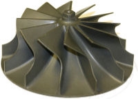
The investment shell for casting a turbocharger rotor

A view of the interior investment shows the smooth surface finish and high level of detail

The completed workpiece
Advantages
Excellent surface finish
High dimensional accuracy
Extremely intricate parts are castable
Almost any metal can be cast
No flash or parting lines
Effective utilization of metal
Fewer environmental hazards from the foundry process
Disadvantages
The main disadvantage is the overall cost, especially for short-run productions. Some of the reasons for the high cost include specialized equipment, costly refractory, and binders, many operations to make a mould, a lot of labor is needed and occasional minute defects occur. However, the cost is still less than producing the same part by machining from bar stock; for example, gun manufacturing has moved to investment casting to lower costs of producing pistols.
Centrifugal casting or rot casting is a casting technique that is typically used to cast thin-walled cylinders. It is typically used to cast materials such as metals, glass, and concrete. A high quality is attainable by control of metallurgy and crystal structure. Unlike most other casting techniques, centrifugal casting is chiefly used to manufacture rotationally symmetric stock materials in standard sizes for further machining, rather than shaped parts tailored to a particular end-use.
Materials
Typical materials that can be centrifugal cast are metals, cements, concretes, glass, and pottery materials. Typical metals cast are iron, steel, stainless steels, and alloys of nickel, aluminum, and copper. Two materials can be combined by introducing a second material during the process. A common example is cast iron pipe coated on the interior with cement.
Process for casting metal
Centrifugal casting
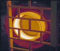
In centrifugal casting, a permanent mold is rotated continuously at high speeds (300 to 3000 rpm) as the molten metal is poured. The molten metal spreads along the inside mold wall, where it solidifies after cooling. The casting is usually a fine-grained casting with an especially fine-grained outer diameter, due to the rapid cooling at the surface of the mold. Lighter impurities and inclusions move towards the inside diameter and can be machined away following the casting.
Casting machines may be either horizontal or vertical-axis. Horizontal axis machines are preferred for long, thin cylinders, vertical machines for rings and bearings.
Castings usually solidify from the outside in. This directional solidification improves some metallurgical properties. Often the inner and outermost layers are removed and only the intermediary columnar zone is used.
Centrifugal casting was the invention of Alfred Krupp, who used it to manufacture railway tyres (cast steel tyres for railway wheels) starting in 1852.
Applications
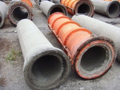
Concrete pipe and form
Typical parts made by this process are pipes, flywheels, cylinder liners, and other parts that are axi-symmetric. It is notably used to cast cylinder liners and sleeve valves for piston engines, parts which could not be reliably manufactured otherwise.
Features of centrifugal casting
Glass
The technique is known in the glass industry as "spinning". The centrifugal force pushes the molten glass against the mold wall, where it solidifies. The cooling process often takes between 16 and 72 hours depending on the impurities or volume of material. Typical products made using this process are television tubes and missile nose cones. [citation needed]
Spin casting is also used to manufacture large telescope mirrors, where the natural curve followed by the molten glass greatly reduces the amount of grinding required. Rather than pouring glass into a mold an entire turntable containing the peripheral mold and the back pattern (a honeycomb pattern to reduce the mass of the finished product) is contained within a furnace and charged with the glass material used. The assembly is then heated and spun at slow speed until the glass is liquid, then gradually cooled over a period of months.
Centrifugal casting is also commonly used to shape glass into spherical objects such as marbles. [citation needed]
Benefits
Cylinders and shapes with rotational symmetry are most commonly cast by this technique. Long castings are often produced with the long axis parallel to the ground rather than standing up in order to distribute the effect of gravity evenly.
Thin-walled cylinders are difficult to cast by other means. Centrifugal casting is particularly suited as they behave in the manner of shallow flat castings relative to the direction of the centrifugal force.
Centrifugal casting is also used to manufacture disk and cylinder shaped objects such as railway carriage wheels or machine fittings where grain, flow, and balance are important to the durability and utility of the finished product.
Noncircular shapes may also be cast providing the shape is relatively constant in radius.
Continuous cast shapes are produced by introducing molten metal into a vertical or horizontal mold that has the ability for rapidly chilling the metal to the point of solidification. The rapid chilling in the mold ensures a fine, uniform grain structure in the solidified metal with higher physical properties than sand castings. Once solidified, the cast shaped bar is cut to the desired length.
The most common shapes produced are tubes and solids, but square, rectangular, hexagonal, and many other irregular shapes can also be produced to match a desired finished part profile.
Molten metal from an induction furnace is fed directly
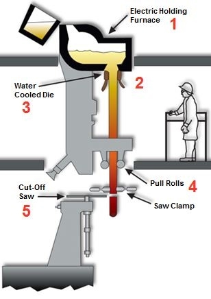
continuous casting diagram
into a mold with the required shape (1). The molten metal enters the die through a series of holes in the upper portion of the mold. Heat is extracted by the water-cooled jacket surrounding the mold, and the metal solidifies. The molten metal above the die acts as a riser keeping the die filled and preventing the formation of shrinkage cavities in the required finished form: bar, tube or special shape (2).
Solidification occurs in the die and then the solidified metal casting exits through the bottom of the die by means of a continuous process of short intermittent extractions performed by a mechanical device (3).
The product is withdrawn at controlled increments and speed until the production length is met (4). Lengths are cut off by a traveling saw which moves with the cast shape. The standard length for continuous cast material is 144 inches (5).
Since continuous casting operates as a true gravity fed bottom-flow casting method, the process minimizes the possible trapping of casual dirt and dross in the casting. Foreign matter in the furnace crucible floats to the top of the melt so it does not become part of the cast product.
Low casting temperatures combined with the chill mold and directional solidification inherent in this process promote a homogeneous, fine-grained, high-density product with high yield.
A horizontal method of continuous casting has also found some favor in the foundry industry. The principle is basically the same as it is for the vertical method, except the equipment stretches out horizontally and is contained on one level. Tube hollows produced by the horizontal method require somewhat more stock allowance to compensate for the natural effect of gravity on ovality and straightness.
continuous casting part
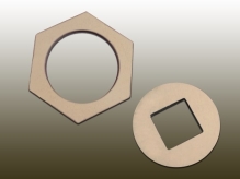
Shapes other than solid round bar and tube hollows are routinely cast by either method. Rectangular, hexagonal, square, gears with teeth, and a multitude of other shapes lend themselves to the continuous cast method. This method is excellent for producing small inside diameters.
Continuous cast products can offer cost advantages over other types of casting if the optimum quantity, shaping, and sizes are chosen.
Advantages Of Continuous Casting
Limitations or Things to Consider
References:
1. R. K. Jain, “Production Technology”, Khanna Publishers
2. K. C. Chawala, “Composite Materials”, Springer, ISBN 978-0387743646, ISBN 978-
0387743653
3. Brent Strong, “Fundamentals of Composites Manufacturing: Materials, Methods”, SME Book series