Unit - 2
Metal Forming Processes
Metal forming is the process which is used to change the size and shape of a part by the application of forces. The force has to be large so that stresses produced in the part are greater than its yield strength but it must be less than its fracture strength. It is necessary to strain the metal beyond its yield point so that the deformation and its new shape is maintained after the removal of force. Forming can be cold forming or hot forming. Forming is the fastest way to change the shape of a part. It is also the most economical process of manufacturing.
1. Elastic and plastic deformation: Deformation is the change in dimensions or form of a material under the action of any applied force or load. The deformation can be (i) elastic or (ii) plastic.
Elastic deformation disappears completely when load is removed. Plastic deformation is a permanent deformation without failure and takes place when elastic range of the deformation has been exceeded. The plastic deformation does not disappear when load is removed.
2. Plastic flow of metals: Metals show a permanent and non-recoverable deformation when stressed beyond a certain minimum stress. This deformation is called plastic deformation.
The plastic deformation takes place as the result of permanent displacement of atoms, molecules or group of both atoms and molecules from their original position in the lattice.
The displaced atoms and molecules do not return to their original position even after the removal of stress.
Now, in case stresses are increased, the metal may show a continuously increasing deformation. This phenomenon is plastic flow of metals. The fluids always show flow when these are subjected to shearing stress
Stress and strain are calculated from easily measurable quantities (normal load, diameter, elongation, original length) and can be plotted against one another as in Figure 2. Such Stress-Strain diagrams are used to study the behavior of a material from the point it is loaded until it breaks. Each material produces a different stress-strain diagram.
Point 1 on the diagram represents the original undeformed, unloaded condition of the material. As the material is loaded, both stress and strain increase, and the plot proceeds from Point 1 to Point 2. If the material is unloaded before Point 2 is reached, then the plot would proceed back down the same line to Point 1.
If the material is unloaded anywhere between Points 1 and 2, then it will return to its original shape, like a rubber band. This type of behavior is termed Elastic and the region between Points 1 and 2 is the Elastic Region.
The Stress-Strain curve also appears linear between Points 1 and 2. In this region stress and strain are proportional. The constant of proportionality is called the Elastic Modulus or Young's Modulus (E). The relationship between stress and strain in this region is given by Equation.

Where
 is the stress (psi)
E is the Modulus (psi)
 is the strain (in/in)
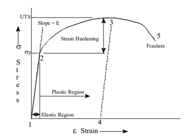
Point 2 is called yield strength. If it is passed, the material will no longer return to itsPoint 2 is called the Yield Strength (original length. It will have some permanent deformation.
This area beyond Point 2 is the Plastic Region. Consider, for example, what happens if we continue along the curve from Point 2 to Point 3, the stress required to continue deformation increases with increasing strain.
If the material is unloaded the curve will proceed from Point 3 to Point 4. The slope (Elastic Modulus) will be the same as the slope between Points 1 and 2. The difference between Points 1 and 4 represents the permanent strain of the material. If the material is loaded again, the curve will proceed from Point 4 to Point 3 with the same Elastic Modulus (slope).
The Elastic Modulus will be unchanged, but the Yield Strength will be increased. Permanently straining the material in order to increase the Yield Strength is called Strain Hardening. If the material is strained beyond Point 3 stress decreases as non-uniform deformation and necking occur.
The sample will eventually reach Point 5 at which it fractures. The largest value of stress on the diagram is called the Tensile Strength (TS) or Ultimate Tensile Strength (UTS). This is the most stress the material can support without breaking.
Re-crystallization temperature is the temperature at which atomic mobility can be repaired when any defect was present in the metal caused by the working process. In this process, the metal is heated to the plastic state, and then the pressure is applied to get various sizes and shapes. When the pressure is applied, the metal grain size will be varied, and the metal’s mechanical properties are improved.
If the pressure is applied by a hand hammer, then it is called hand or smith forging. If hand hammering is replaced by power hammers, then it is called hammer forging. Such a type of hot working of metals is called hot forging. Hot-working can be used for forging, extrusion, and drawing, etc.
When metals are worked above the re-crystallization temperature, then it becomes plastic and causes the growth of grains. During the hot working, the grains become loosened in their structure, and they realign properly. Only small pressure is required to shape the metal.
Advantages of Hot Working
1. It is applicable for mass production work.
2. The metal size and shape can be easily changed.
3. Metalworking is done under high temperatures; therefore, larger deformation is possible.
4. Metal grain structure will be refined.
5. Stresses and other defects can be minimized.
6. Hot-working leads to a homogeneous structure of metal without defects and blowholes.
7. Mechanical, physical, and chemical properties of metals can be improved.
8. Hot-working removes all types of imperfections caused by the Gas pores and composition differences.
9. Metal reaches to anisotropic behaviour.
10. Metal regains softness and ductility after the process.
11. Hot working is a fast, reliable, and economical process.
2. Hot-working leads to poor surface finish due to oxidation, because the material will be worked under high temperature.
3. Sometimes it leads to lower strength due to loss of carbon due to oxidation.
4. On account of the loss of carbon from the surface of the steel piece being worked, the surface layer loses its strength, which is a disadvantage when the part is put to service.
5. It is difficult to attain dimensional accuracy due to uneven shrinkage of metal.
What is Cold Working
Soft, ductile, and malleable metals can be easily worked with cold working. But this process leads to hardness and distorted grain structure. The cold working process is used in the rolling, bending, spinning process, etc.
The cold working process also affects the following mechanical properties of metals significantly.
1. Hardness.
2. Yield Strength.
3. Ductility.
4. Tensile Strength.
Advantages of Cold Working
1. Dimensional accuracy can be maintained.
2. No heating of metals.
3. Better surface finish can be achieved since there is no oxidation during the cold working of metals.
4. Strength and hardness of the metal are increased.
5. Due to cold working, metal gains strength and hardness.
6. Better strength and wear properties of the material can be achieved.
Disadvantages of Cold Working
1. It leads to brittleness if the metals are worked under cold working.
2. Metals hardness is increased.
3. Cold worked components require a heat-treatment process.
4. Only ductile and malleable materials are suitable for cold working.
5. Greater force is essential for deformation. Therefore powerful machines are required.
Plastic deformation
When a sufficient load is applied to a metal or other structural material, it will cause the material to change shape. This change in shape is called deformation. A temporary shape change that is self-reversing after the force is removed, so that the object returns to its original shape, is called elastic deformation. In other words, elastic deformation is a change in the shape of a material at low stress that is recoverable after the stress is removed. This type of deformation involves stretching of the bonds, but the atoms do not slip past each other.
When the stress is sufficient to permanently deform the metal, it is called plastic deformation. As discussed in the section on crystal defects, plastic deformation involves the breaking of a limited number of atomic bonds by the movement of dislocations. Recall that the force needed to break the bonds of all the atoms in a crystal plane all at once is very great. However, the movement of dislocations allows atoms in crystal planes to slip past one another at much lower stress levels. Since the energy required to move is lowest along the densest planes of atoms, dislocations have a preferred direction of travel within a grain of the material. This results in a slip that occurs along parallel planes within the grain. These parallel slip planes group together to form slip bands, which can be seen with an optical microscope. A slipped band appears as a single line under the microscope, but it is made up of closely spaced parallel slip planes as shown in the image.
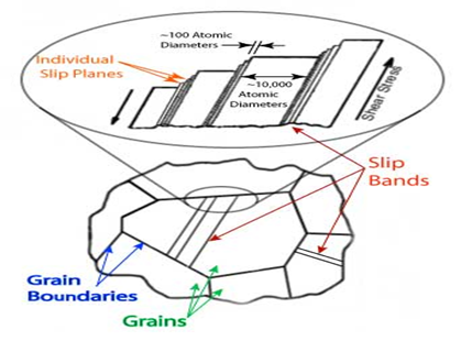
For most metallic materials, the elastic deformation region is relatively small. At some point, the strain is no longer proportional to the applied stress. At this point, bonds with original atom neighbours start to break and reform with a new group of atoms. When this occurs and the stress is relieved, the material will no longer return to its original form, i.e., the deformation is permanent and non-recoverable. The material has now moved into the region referred to as plastic deformation. In practice, it is difficult to identify the exact point at which material moves from the elastic region to the plastic region. As shown in the figure below, a parallel line offset by 0.002 strain is drawn. Where that line intercepts the stress-strain curve is identified as the yield strength. The yield strength is equal to the stress at which noticeable plastic deformation has occurred.
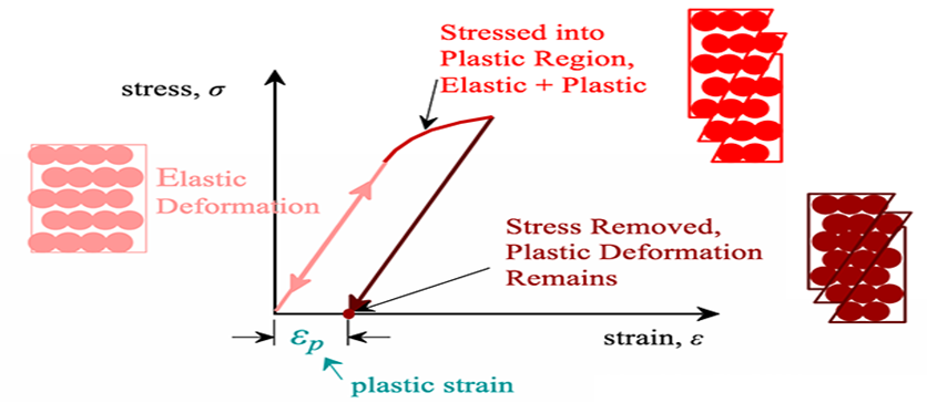
Fig: Stress and strain
For many materials, the stress-strain curve looks like the curve shown in the figure below. As the stress is increased from zero, the strain increases linearly until it starts to deviate from linear at the yield strength. For increasing stress, the curve proceeds to a maximum at which point it curves downward toward the fracture point. The maximum corresponds to the tensile strength, which is the maximum stress value for the curve, and is indicated by M in the figure. The fracture point is the point at which the material ultimately breaks, indicated by F in the figure.
Factors affecting the plastic deformation are:
(a) Applied stress: The plastic deformation depends upon the applied stress. The applied stress has to be higher than the yield strength and lower than the fracture strength. The plastic deformation increases with the applied stresses when these stresses are in between the yield strength and the fracture strength.
(b) Deformation temperature: The metal strength decreases as the temperature is increased. Metal plasticity is greatest when deformation temperature is above the recrystallisation temperature but below the melting point of the metal. Recrystallisation temperature is the temperature at which the material becomes sufficient plastic for deformation due to the formation of new grains which can flow in the direction of elongation.
(c) Strain rate: The change of deformation in a unit time is called strain rate. The plastic deformation is more at higher strain rate. However, higher strain rate is possible at elevated temperature when metal becomes more plastic.
The yield strength or yield point of a material is defined as the stress at which a material begins to deform plastically. For loading less than yield point, the material will deform elastically and it will return to original shape when the loading is removed. Once the yield point is passed, some fraction of the deformation will be permanent and non-reversible. Knowledge of the yield point is vital when designing a component as it represents the upper limit to the load which can be applied on the component. The yield point is also important for the control of many manufacturing processes such as (i) forging, (ii) rolling and (iii) bending in which the material has to be plastically deformed.
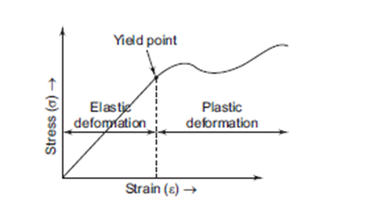
Fig. Yeilding
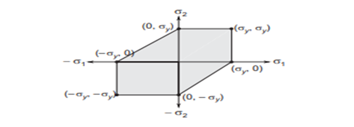
The stress required for plastic deformation or to make the metal flow to any given strain can be obtained from the true stress true strain curve. True stress true strain curve gives an idea about how the metal can flow plastically. Hence, it is referred to as “Flow Curve”.
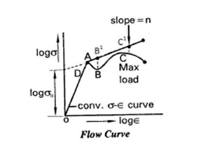
Consider the stress strain curve for a metal from the start of plastic flow to the maximum load at which the metal begins to form neck (BC). BC represent strain hardening region.
Taking log values of  and
and  for portion B to C, a stress strain curve can be plotted, which is a straight line
  is extended back it will intercept the
  axis at D.
Let ‘n’ be the slope of the line  which represents strain hardening portion BC of the stress strain curve, This slope n, is referred to as “strain hardening coefficient”.
Let the straight line  cut the
  axis at the origin.
Let  be the intercept has shown in the figure.
Then  is the equation for a straight line.
Equation of the stress at any point on the line.


This equation is referred to as “Flow Stress Equation”.
The Forming Limit Diagram (FLD) together with the Forming Limit Curve (FLC) provide a method for determining process limitations in sheet metal forming and are used to assess the stamping characteristics of sheet metal materials.
Usually, the Forming Limit Diagram is used in method planning, tool manufacturing and in tool shops to optimize stamping tools and their geometries.
The comparison of deformations on stamped metal sheets with the FLD leads to a security estimation of the stamping process. The forming analysis and the comparison of the data with the FLC provide for a reliable assessment of sheet metal forming processes.
In case of problems with the stamping tools used, the sheet metal forming process can be optimized (e.g., board and tool geometries, blank holder pressure, lubrication, material) based on the ARGUS measurements (see also “Optimization of Metal Forming Tools by Forming Limit Analysis “).
Additional important fields of application for FLDs are numerical simulations of transformation processes. The FLC of the material used represents characteristic material identification data for the forming simulations.
Normally, the material manufacturer determines the Forming Limit Curves according to the Nakajima or Marciniak tests. This way, the material quality can be clearly defined which helps the customer to choose the right material.
2.8.1 Rolling terminology:
The process of shaping metals into semi-finished or finished forms by passing between rollers is called rolling. Rolling is the most widely used metal forming process. It is employed to convert metal ingots to simple stock members like blooms, billets, slabs, sheets, plates, strips etc.
In rolling, the metal is plastically deformed by passing it between rollers rotating in opposite direction. The main objective of rolling is to decrease the thickness of the metal. Ordinarily, there is negligible increase in width, so that the decrease in thickness results in an increase in length.
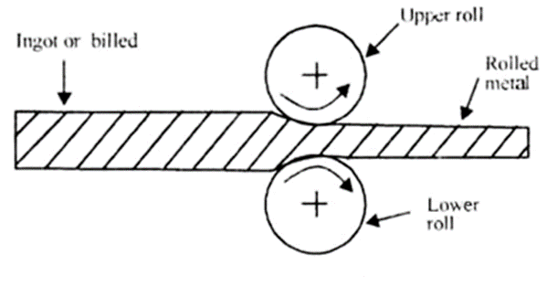
Operation of rolling
Rolling is done both hot and cold. It is accomplishes in rolling mills. A rolling mill is a complex machine having two or more working rollers, supporting rollers, roll stands, drive motor, reducing gear, flywheel, coupling gear etc.
Rollers may be plain or grooved depends upon the shape of rolled product. The metal changes its shape gradually during the period in which it is in contact with the two rollers. The range of products that can be produced by rolling is very large. Rolling is a more economical method of deformation than forging when metal is required in long lengths of uniform cross-section.
It is one of the most widely used among all the metal working processes, because of its higher productivity and lower cost. The materials commonly rolled are steel, copper, magnesium, aluminum and their alloys.
2.8.2 Friction in rolling
The rolling is a process which consists of passing the metal through a gap between rollers rotating in opposite direction. This gap is smaller than the thickness of the part being worked. Therefore, the rollers compress the metal while simultaneously shifting it forward because of the friction at the roller-metal interfaces.
When the work piece completely passes through the gap between the rollers, it is considered fully worked. As a result, the thickness of the work is decreases while its length and width increases.
However, the increase in width is insignificant and is usually neglected. The Fig. 2.4 shows the simple rolling operation of a plate. The decrease in thickness is called draft, whereas the increase in length is termed as absolute elongation. The increase in width is known as absolute spread.
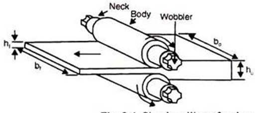
Fig. Simple rolling of a plate
2.8.3 Calculation of rolling load
Two other terms are the relative draft and the coefficient of elongation can be given as follows:
Relative draft 

Since the volume of the work is constant, hence  can be given as,

Where,


The above equation (3) shows that coefficient of elongation is adversely proportional to the ratio of final to original cross-sectional areas of the work. Also, equation (2) shows that coefficient of elongation is proportional to the ratio of final lo original lengths of the work.
Fig. shows the deformation zone, state of stress, angle of contact in rolling process. The metal is deformed in the shaded area, known as deformation zone. The metal does not undergo any deformation before and after deformation zone.
It can also be seen that the metal undergoing deformation is in contact with each of the roller along the arc AB. The arc-AB is called the arc of contact. Its corresponding angle (α) is called the angle of contact, or the angle of bite.
From the geometry of the drawing and by applying simple trigonometry, the angle of bite can be given as:
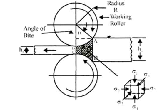
Deformation Zone, State of Stress and Angle of Contact on Rolling

The above equation (4) gives the relationship between the geometry parameters of the rolling process, the angle of bite, the draft, and the radius of rollers.
In order to ensure that the metal will be shifted by friction, the angle of contact (α) must be less than the angle of Friction (β), where tan β = µ (the coefficient of friction between roller surface and metal).
The maximum permissible value of angle of contact (α) depends upon other factors like:
(i) Material of the rollers.
(ii) Material of work being rolled.
(iii) Temperature of rolling.
Forging
Forging is a basic process in which the work piece is shaped by compressive forces applied through various dies and tooling. It is one of the oldest and most important metalworking operations used to make jewelry, coins, and various implements by hammering metal with tools made of stone. Forged parts now include large rotors for turbines; gears; bolts and rivets; cutlery); hand tools; numerous structural components for machinery, aircraft and railroads and a variety of other transportation equipment.
Simple forging operations can be performed with a heavy hammer and an anvil, as has been done traditionally by blacksmiths. However, most forgings require a set of dies and such equipment as a press or a powered forging hammer.
Forging may be carried out at room temperature (cold forging) or at elevated temperatures (warm or hot forging) depending on the homologous temperature. Cold forging requires higher forces (because of the higher strength of the work piece material), and the work piece material must possess sufficient ductility at room temperature to undergo the necessary deformation without cracking. Cold-forged parts have a good surface finish and dimensional accuracy. Hot forging requires lower forces, but the dimensional accuracy and surface finish of the parts are not as good as in cold forging. Forgings generally are subjected to additional finishing operations, such as heat treating to modify properties and machining to obtain accurate final dimensions and a
good surface finish. These finishing operations can be minimized by precision forging, which is an important example of net-shape or near-net-shape
forming processes. As we shall seen components that can be forged successfully also may be manufactured economically by other methods, such as casting, powder metallurgy, or machining .Each of these will produce a part having different characteristics, particularly with regard to strength, toughness, dimensional accuracy, surface finish, and the possibility of internal or external defects.
In forging the material is deformed applying either impact load or gradual load. Based on the type of loading, forging is classified as hammer forging or press forging. Hammer forging involves impact load, while press forging involves gradual loads.
Based on the nature of material flow and constraint on flow by the die/punch, forging is classified as open die forging, impression die forging and flash less forging.
2.9.1 OPEN DIE FORGING:
In this, the work piece is compressed between two platens. There is no constraint to material flow in lateral direction. Open die forging is a process by which products are made through a series of incremental deformation using dies of relatively simple shape. The top die is attached to ram and bottom die is attached to the hammer anvil or press bed. Metal work piece is heated above recrystalline temp from 1900 to 24000c.Most open die forging are produced on flat dies. Convex surface dies and concave surface dies are also used in pairs or with flat dies.
Open die forging is classified into three main types, namely, cogging, fullering and edging. Cogging: Cogging (also called as drawing out) consists of a sequence in which the thickness of an ingot is reduced to billet or blooms by narrow dies. Fullering and Edging operations are done to reduce the cross section using convex shaped or concave shaped dies. Material gets distributed and hence gets elongated and reduction in thickness happens. Upsetting is an open die forging in which the billet is subjected to lateral flow by the flat die and punch. Due to friction the material flow across the thickness is non-uniform. Material adjacent to the die gets restrained from flowing, whereas, the material at center flows freely. This causes a phenomenon called barreling in upset forging.
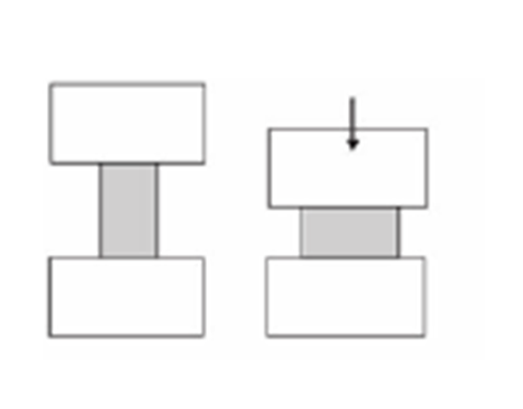
Open die forging
IMPRESSION DIE FORGING
Here half the impression of the finished forging is sunk or made in the top die and other half of the impression is sunk in the bottom die. In impression die forging, the work piece is pressed between the dies. As the metal spreads to fill up the cavities sunk in the dies, the requisite shape is formed between the closing dies. Some material which is forced out of the dies is called “flash”. The flash provides some cushioning for the dies, as the top strikes the anvil. The flash around the work piece is cut and discarded as scrap. For a good forging, the impression in the dies has to be completely filled by the material. This may require several blows of the hammer, a single blow may not be sufficient.
2.9.2 CLOSED DIE FORGING
Closed die forging is very similar to impression die forging, but in true closed die forging, the amount of material initially taken is very carefully controlled, so that no flash is formed. Otherwise, the process is similar to impression die forging. It is a technique which is suitable for mass production.
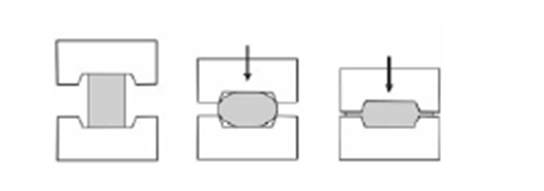
Closed die forging
2.9.3 Forging operations
1. Cutting Operation
To make small of long metal rods and plates is known as cutting. This can be done both in cold or hot condition. For cold metals, the chisel of cutting angle is used. For hot metals, the chisel of cutting angle is used. Metal beyond the thickness of 20mm should be cut only after heating it.
2. Upsetting Operation
This operation applied to increase the cross-sectional area of the stock over the length extension. The offsetting force is used in a direction parallel to the long axis to achieve the length, for example, the development of the bolt head.
3. Drawing Out Operation
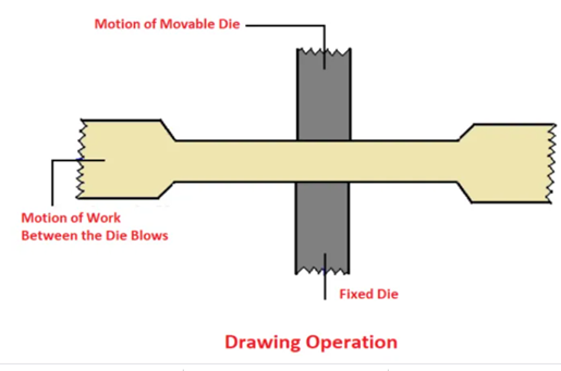
Forging operations - Drawing Operation
To increase metals length is called Drawing out. This has been shown in the figure. The metal is heated at a temperature between to and the hammer is struck at the beak of the anvil. Fuller is also used for this purpose.
4. Jumping Operation
To shorten and thicken a piece of metal after heating it is called jumping or upsetting. By jumping the length of the metal can be reduced to almost half. Jumping is done is three ways:
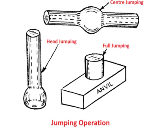
Jumping Operation
Head jumping: This has been shown in figure. Jumping of one end of a round rod is called “Head jumping” such as rivet head. Centre jumping: This has been illustrated in figure. In this category. Jumping is done in any other part except the two corners of the round metal rod. Example: Tap handle. Full jumping: This has been shown in figure. The metal is completely heated and its length is reduced.
5. Bending Operation
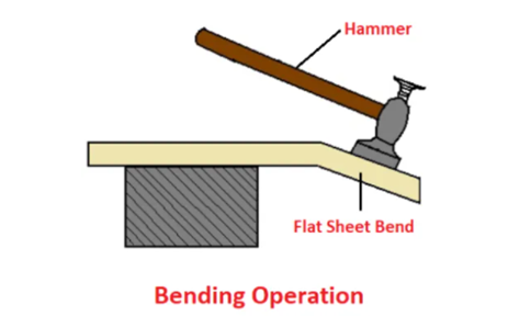
Bending operation
To turn or bend a piece of metal in round or angular form is called “bending”. This has been shown in the figure below. Round rings etc. are made through this operation.
6. Fullering Operation
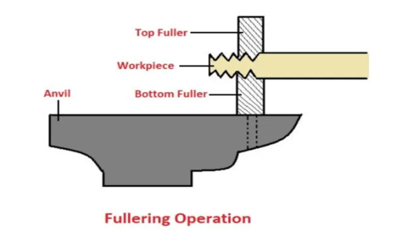
Forging operations - Fullering
This forging operation is by placing the bottom fuller into an angle hole with hot metal, the top filler is then placed on top of the metal, force is applied through the top filler with the help of a sledge hammer.
7. Edging Operation
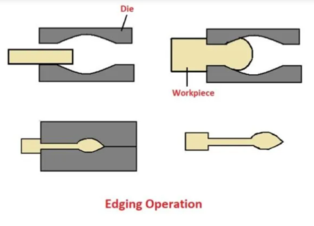
Forging operations - Edging Operation
This forging operation is performed by striking or forcing the metal plate to the desired shape. The workpiece is forced between two die edges.
8. Punching Operation
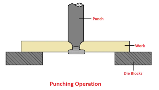
Punching Operation
This has been shown in the figure. In this operation, the hole is made in hot metal with the help of a punch. For punching, the job is first placed on the punch hole of the anvil or a nut etc., and the hole is made with punch or holes already made by drift are enlarged.
9. Setting Down Operation
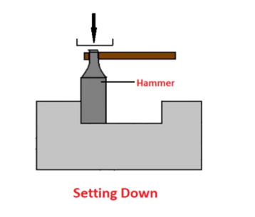
Setting Down Operation
This is the finishing process. The ends and corners of forged metals are made plain and to bring roundness when their seams are closed. Swage and set hammers are used for this purpose. Apart from this, twisting an also done to provide strength to a job.
10. Forge Welding Operation
Under this process, the parts of metals are brought to a suitable temperature in a furnace and welded by pressure or blows. For forge welding, the ends of the pieces of metals are made scarf through jumping.
11. Swaging Operation
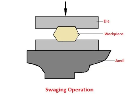
Swaging is done to decrease and complete work for the desire shape and size, usually either round or hexagonal. In this operation, the top and bottom pairs are added for small jobs, where the swag block can be used for larger jobs.
The Extrusion Type and Process
Extrusion is a method of forming in which metals or plastics are forced through a die or series of dies, resulting in a specific shape of constant cross section. With the proper tooling, extrusions may be tapered or stepped. Extrusions can be either very thick in cross section or very thin and be either solid or hollow. The extruded stock, which can be 100 feet in length or longer, is then cut to a convenient stock size and used as specific products, assembly components, or as raw stock material for further processing. Extrusion size is expressed as a circle size which relates to the smallest circle diameter which can enclose an extrusion’s cross section.
Metal Extrusion
Metal extrusion processes may be performed hot, warm, or cold. Each method has its own unique operating parameters.
Hot Extrusion
Hot Extrusion uses heated feedstock, called a billet, that ranges in temperature from 200° to 2,300° Fahrenheit, or 90° to 1,260° Celsius depending on the material.
Aluminum is the most common hot extruded material, with billet temperatures ranging from 575° to 1,100° Fahrenheit, or 300° to 600° Celsius. Hot extrusion is always performed at temperatures much higher than the recrystallization temperature of the material to be extruded. The heated billet is confined in a container, force is applied and the billet is extruded through a die or dies.
Hot extrusion is used to produce close tolerance dimensions as well as smooth, fine surfaces. Additionally, and depending on the metal used, improved microstructures are obtained. The process is also very economical in that most of the metal extruded is usable.
The primary type of hot extrusion is direct, or forward, extrusion. Direct extrusion is commonly performed in horizontal hydraulic presses. The heated billet is loaded into a thick-walled container from which it is pushed through the extrusion die by a ram. Between the ram and the billet is an intermediate dummy block.
Lubrication is used to reduce friction along the billet length and its container. In operation, force increases rapidly as the billet is upset to fill the container, then increases further as breakthrough force before extrusion
begins. Upon breakthrough, the force declines as billet length decreases until a minimum force is reached. as the billet thins, the force rapidly rises again to continue metal flow radially toward the die opening.
Warm and Cold Extrusion Processes
Warm extrusion refers to the extruding of feedstock or billet while it is above room temperature, but well below the recrystallization temperatures used in hot extrusion. Cold extrusion refers to extrusion at room temperatures. Because the feedstock is at lower temperatures, no micro-structural changes occur during processing.
Warm and cold extrusion processes increase the strength and hardness of the finished extrusion. Reduced heat also lowers pollution concerns and eliminates costly high temperature tooling. While virtually all metals may be warm and cold extruded, those having the highest ductility are more suited for processing. Warm and cold extrusion processes are commonly integrated into continuous and semi-continuous manufacturing operations, with the three primary methods including:
Indirect extrusion, which is also called backward extrusion, is used to produce hollow shapes with the inside diameter defined by the male punch and the outside diameter controlled by the female die.
Combination extrusion combines various types of extruding including direct and indirect methods to produce more complex shapes.
Impact extrusion is similar to the other extrusion methods described, but is a much faster process. Using shorter strokes and shallower dies, punch impact moves the feedstock slug either up, down, or in both directions at once, without being completely confined by either the punch or die walls. Ductile and low melting point metals such as tin, aluminum, zinc, and copper are well suited for impact extruding.
Plastics Extrusion
Plastics extrusion is a continuous process in which thermoplastic feedstock is converted to a molten, viscous fluid and then extruded into various shapes such as bar, rod, tube, and pipe. Plastic extrusion is also used to produce various profiles such as angles and channel shapes as well as mono-filaments and wiring insulation.
The most commonly extruded thermoplastics include nylon, polycarbonate, polyethylene, and polyvinyl chloride. Plastic extrusions are performed in a screw extrusion machine, with the machine’s main components including a hopper, externally heated feed barrel, helically fluted extruder screw, and die assembly.
As the feedstock enters the feed barrel it is moved forward by the rotating screw. The feedstock is heated by its frictional movement as it is dragged forward. External heating bands help to bring the material to its final temperature.
Typical extruder screws move the thermoplastic material through four zones: Feed zone – in which trapped air is forced from the stock. The feed zone has a constant flight depth. The flight depth is the distance between the major diameter at the top of the flight, and minor diameter of the screw at the base of the flight.
Transition zone – in this zone the flight depth decreases, compressing and plasticized the thermoplastic material.
Mixing zone – here the flight depth is constant and there may be a special mixing element to ensure the feedstock is completely plasticized and mixed into a homogenous blend.
Metering zone – the flight depth here is also constant but much smaller than in the mixing zone. This section acts as a pump forcing the material through the extruder die assembly.
The two principal plastic extrusion processes are:
Profile extrusion is a horizontal process producing long continuous shapes which are cooled in long cooling tanks filled with water after exiting the die assembly. A final cutting operation reduces the extrusion to stock lengths for later use.
Blown film extrusion is a vertical process where molten plastic passes through a die having a 360 degree annular opening. The tubular film produced is then filled with air. As a result, the tube expands out into a bubble having a diameter larger than the diameter of the annular opening of the die. As the tube cools, it is pulled up and flattened as it passes through a series of rolls. These rolls maintain tension on the plastic film as it is eventually wound into a coil for later use.
2.11.1 Wire and Tube drawing process
Drawing is an operation in which the cross-section of solid rod, wire or tubing is reduced or changed in shape by pulling it through a die. The principle of this procedure consists of reducing the thickness of a pointed, tapered wire by drawing it through a conical opening in a tool made of a hard material. The wire will take shape of the hole. Drawing improves strength and hardness when these properties are to be developed by cold work and not by subsequent heat treatment.
This process is widely used for the production of thicker walled seamless tubes and cylinders therefore; shafts, spindles, and small pistons and as the raw material for fasteners such as rivets, bolts, screws. Drawing is classified as
1. Wire drawing
2. Tube drawing
Wire Drawing:-
Wire drawing is a metal-reducing process in which a wire rod is pulled or drawn through a single die or a series of continuous dies, thereby reducing its diameter. Because the volume of the wire remains the same, the length of the wire changes according to its new diameter. Various wire tempers can be produced by a series of drawing and annealing operations. (Temper refers to toughness.) (a)
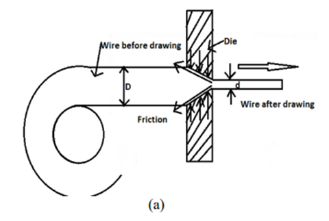
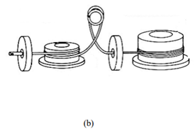
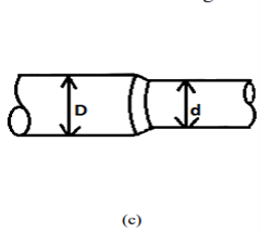
Figure-(a)Wire Drawing sectional view (b) wire drawing set up (c) Enlarge View of Wire Reduction
Process Characteristics
Tube Drawing
When a hollow tube is drawn through a die, generally a mandrel or plug is used to support the inside diameter of the tube, this process is called tube drawing. The function of the plug is to effect wall reduction and to control the size of the hole. However, the mandrel may be omitted if it is not necessary to make a reduction in the wall thickness, or if the dimensions and surface of the inside are not important. The process to draw a pipe without any mandrel is known as tube sinking.
In drawing tubes over a stationary mandrel, the maximum practical sectional area reduction does not exceed 40 per cent per pass due to the increased friction from the mandrel. If a carefully matched mandrel floats in the throat of the die, it is possible to achieve a reduction in area of 45 percent, and for the same reduction the drawing loads are lower than for drawing with a fixed plug. This style is called the drawing with floating plug. It is worth mentioning here that in this style, the tool design and lubrication can be very critical. Problems with friction in tube drawing are minimized in drawing with a long mandrel. The mandrel consists of a long hard rod or wire that extends over the entire length of the tube and is drawn through the die with the tube.
In this design, the area reduction can be 50 per cent. However, after drawing, the mandrel must be removed from the tube by rolling (reeling), which increases the tube diameter slightly and disturbs the dimensional tolerances. The drawing process discussed above has been illustrated in the figure
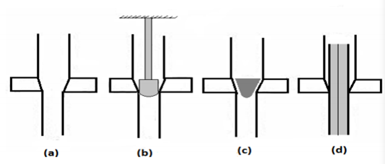
Figure-Tube drawing processes. (a) Sinking; (b) fixed plug; (c) floating plug; (d) moving mandrel
Defects in drawing process:

Figure (a) Wrinkling in the flange or (b) in the wall (c) tearing, (d) Earing, (e) surface scratches
Basic press working Operation
Sheet metal working is also a metal forming operation where the material being worked is in the form of sheets the working is usually at room temperature. The process is called the press working of sheet metal. For sheet metal working a set of die and punch assembly is normally used to obtain various components from a sheet metal.
Die and Punch assembly
A simple die and punch assembly also called die-set is shown in figure. The parts of the die and punch system are labeled. This assembly is mounted on press.
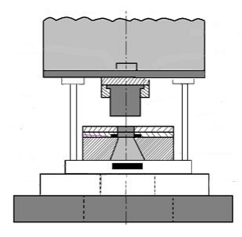
Figure-Die and Punch Assembly
The press supports a ram (slide) that holds a punch and a bed that holds the die in a die holder connected to the bolster plate. In sheet metal working operation, the sheet thickness remains
almost constant. The process has the following advantage:
1. The part fabricated are light in weight
2. High labor productivity
3. High efficiency of the process
4. Gives close tolerance
The important characteristic of the sheet material is its formability i.e. its ability to stretch uniformly (resistance to thinning). Various tests are available to assess the formability of sheet. Some problem arise out of sheet used being thin, such as spring back. Buckling, and wrinkling. A proper die design and minimizing the unsupported length during processing may solve the problem.
2.11.2 Die profile:
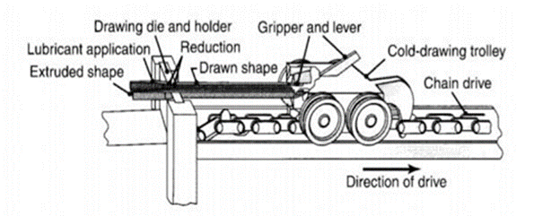
Although it is available in several designs, the equipment for drawing is basically of two types: the draw bench and the bull block. A draw bench contains a single die, and its design is similar to that of a long, horizontal tension-testing machine (Fig. 1523).
The pulling force is supplied by a chain drive or is activated hydraulically. Draw benches are used for a single-length drawing of straight rods and tubes with diameters larger than 20 mm and lengths up to 30 m. Machine capacities reach 1.3 MN of pulling force with a speed range of 6 to 60 m/min.
Very long rods and wire (many kilometers) and wire of smaller cross sections, usually less than 13 mm, are drawn by a rotating drum (bull block or capstan, Fig. 1524). The tension in this setup provides the force required for drawing the wire, usually through multiple dies (tandem drawing).
Die Design
The characteristic features of a typical die for drawing are shown in Fig. 15.21. Die angles usually range from 6° to 15°. Note, however, that there are two angles (entering and approach) in a typical die. The purpose of the bearing surface (land) is to set the final diameter of the product (sizing) and to maintain this diameter even with wear on the die-workpiece interface. A set of dies is required for profile drawing, which involves various stages of deformation to produce the final profile. The dies may be made in one piece or (depending on the complexity of the cross-sectional profile) with several segments held together in a retaining ring. Computer-aided Casing sign techniques are being implemented to design dies for smooth material E flow, as well as to minimize defects. A set of idling cylindrical or shaped rolls also may be used in drawing rods or bars of various shapes. Such an arrangement
2.11.3 Friction and lubrication in metal forming
Friction and lubrication are of vital importance in most metal forming operations. Effective lubrication systems result in low friction levels which reduce the loads imposed on tooling and workpieces.
This can eliminate problems with tooling or workpiece failures or permit a reduction in the number of steps required to form a part. Lower force levels also reduce tooling deflection and can improve the dimensional accuracy of the product.
The presence of an effective lubricant film also reduces the amount of direct surface contact between the workpiece and tooling. This increases tooling life by reducing wear and improves product quality by reducing the incidence of scoring and other surface defects.
On the other hand, an overly thick lubricant film may result in a roughened workpiece surface due to lack of constraint by the tooling. Thermal problems are often eliminated by effective lubrication which not only reduces the amount of frictional heating but may also provide an insulating film between the workpiece and the tooling.
This may allow the use of higher speeds or reduce thermally induced residual stresses or metallurgical damage in the
product. Despite the importance of lubrication in metal forming, there is relatively little interaction between researchers in the two fields. Thus, it is common to find
sophisticated treatments of plasticity combined with naive assumptions about frictional conditions in a single model of a forming process.
The predictions of such a model can often be extremely misleading. For example, a model which allows for the effects of tooling geometry on the mode of deformation, but neglects the effects on friction and lubrication may suggest tooling geometries which are far from optimum.
At present, understanding of the basic mechanisms of metal forming lubrication is advancing at a rapid rate. In particular it is possible to explain many observed phenomena using mechanical models of the lubrication processes involved.
However, most of this activity has been concentrated on "bulk" deformation processes such as extrusion, rolling and forging and relatively little on sheet metal forming.
2.11.4 Forming defects:
References:
1. R. K. Jain, “Production Technology”, Khanna Publishers
2. K. C. Chawala, “Composite Materials”, Springer, ISBN 978-0387743646, ISBN 978-
0387743653
3. Brent Strong, “Fundamentals of Composites Manufacturing: Materials, Methods”, SME Book series