UNIT 1
Fundamentals of Mechanism
Each half of a machine that moves relative to another part, is thought of as a kinematic link (or merely link) or component. A link could include many elements that square measure bolt fixed along, so that they are doing not move relative to at least one another. for instance, during a reciprocatory external-combustion engine as shown in the figure.1.1 piston, connecting rod, and crosshead represent one link; a rod with huge and little finish bearing represent a second link; crank, rotating shaft and regulator as the third link and also the cylinder engine frame and main bearings as the fourth link.
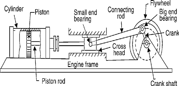
Figure.1.1 Reciprocating Steam Engine
A link or component needn't be a rigid body, however, it should be a resistant body. A body is claimed to be a resistant body if it's capable of transmitting the desired forces with negligible deformation. Thus, a link ought to have the following deformation ought to have following 2 characteristics:
1. It ought to have relative motion
2. It should be a resistant body.
Key Takeaways:
Concept of link, relative movement of link, the reciprocating steam engine, characterisitics of deformation.
There square measure essentially four styles of the link that are:
1. Rigid Link
2. Versatile link
3. Fluid Link
4. Floating Link
2. Versatile Link: a versatile link is one that whereas transmission motion is part misshapen during a manner to not affect the transmission of motion. for instance, spring, chain, rope, belt, etc.
3. Fluid Link: A fluid link is one that's misshapen by having a fluid during a closed vessel and also the motion is transmitted through the fluid by pressure. for instance, press and hydraulic jack.
4. Floating Link: A floating link is one that's not connected to the frame.
A link can also be classified based upon its number and its end vertices:
Key Takeaways:
Link types and their description
The 2 links or parts of a machine, once in grips with one another, square measure aforesaid to create a pair. If the relative motion between them is totally or with success forced the pair is thought of as kinematic pair.
Classification of pair is based on:
Sliding Pair: The 2 parts have a slippy motion relative to every alternative. Example: Piston and cylinder try rectangular rod is a rectangular line.
Turning Pair: Once the 2 parts square measure connected such the component revolves around the opposite component. Example: Shaft rotates within the bearing rotation of a crank during a slider-crank mechanism.
Rolling pair: once one component is absolved to roll on another component. Example: The belt and simple machine surfaces represent a rolling try.
Screw Pair: During this sort the contacting surface has threads. it's additionally known as a whorled try one component turns concerning another component by suggests that of thread solely. Example: A bolt and nut arrangement jack for lifting serious weights.
Spherical Pair: One component is within the type of sphere and turns concerning the fastened element; Example: ball and socket joint
2. In step with the sort of contact between the weather.
Lower Pair: If a try motion has surface contact between the weather. Example: Piston reciprocatory during a cylinder Shaft rotates during a bearing. (Contacting surfaces square measure similar)
Higher Pair: In higher try, there's a line or purpose contact between the weather.
Example: Cam and follower. (Contact surfaces square measure differently.)
3. In step with the sort of closure.
Self-Closed Pair: In this pair, two elements are held together mechanically; Example: All lower pair
Unclosed Pair/Force Closed Pair: The two elements are not held together mechanically; Example: Cam and followers.
Key Takeaways:
Kinematic pairs and their types, lower pair, higher pair, screw pair, turning pair and to know the exact similarity and difference between the two.
Completely Constrained Motion: Once the motion between the try is restricted to a certain direction no matter the direction of force applied, then the motion is claimed to be a very forced motion. for instance, the piston and cylinder (in a steam engine) type a try, and also the motion of a piston is restricted to a certain direction (i.e., it'll solely reciprocate) relative to the cylinder no matter the direction of the motion of the crank as in figure1.1. The motion of a sq. bar during a sq. hole as shown in figure 1.2 (a) and also the motion of a shaft with collars at every finish during a circular hole as shown in figure 1.2 (b). also are samples of success constrained motion.

Figure 1.2. (a) Figure 1.2 (b)
Incompletely Constrained Motion: When the motion between the trial takes place in an additional than one direction, such motion is thought as incompletely forced motion e.g., a circular bar during a circular hole fig.1.3 because the bar will reciprocate or rotate, each the motion haven't any relationship between them.

Figure.1.3. Shaft in a Circular Hole
Successfully Constrained Motion: When the motion between the weather, forming a try is such the forced motion isn't completed by itself, however by another suggests that then the motion is claimed to be with success forced motion. take into account a shaft during a footstep bearing as shown in figure1.4. The shaft could rotate during a bearing or it's going to move upwards. this can be a case of incompletely forced motion. however, if the load is placed on the shaft to forestall axial upward movement of the shaft then the motion of the try is claimed to be with success forced motion. The motion of associate degree I.C. engine valve (these square measures unbroken on their seat by a spring) and also the piston reciprocatory within the associate degree engine cylinder also are samples of with success forced motion.

Figure.1.4. Shaft in a footstep bearing
Key Takeaways:
Constrained motions, Incompletely constrained motion, Successfully constrained motion, Completely constrained motion, understanding of the concept of constraints.
When the kinematic pairs square measure coupled in such a way that the last link is joined to the primary link to transmit definite motion (i.e., utterly or with success affected motion) it is known as a kinematic chain. In alternative words, is also outlined as a mixture of kinematic pairs, joined in such the way that every link forms a neighborhood of 2 pairs and therefore the relative motion between the links or parts is totally or with success affected motion.
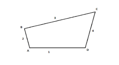
Figure.1.5. Kinematic Chain
When the kinematic pairs square measure coupled in such a way that the last link is joined to the primary link to transmit definite motion (i.e., utterly or with success affected motion) it's known as a kinematic chain. In alternative words, is also outlined as a mixture of kinematic pairs, joined in such the way that every link forms a neighborhood of 2 pairs and therefore the relative motion between the links or parts is totally or with success affected motion.
If every link is assumed to make 2 pairs with 2 adjacent links, then the relation between range the amount the quantity} of pairs (p) forming a kinematic chain and also the number of links (l) is also expressed within the style of associate degree equation:
l=2p-4
During a kinematic chain, every link forms a district of 2 pairs. Another relation between range the amount the quantity of links (l) and also the number of joints (j) that represent a kinematic chain is given by the expression:
j= 3/ (2l -2)
If within the example,
L.H.S > R.H.S, then it's thought-about as a barred chain
L.H.S = R.H.S, then it's thought-about mutually D.O.F
L.H.S < R.H.S, then it's thought-about as free Chain
Key Takeaways:
Kinematic chain, the formula of kinematic chain l=2p-4, the formula for the expression of joints, j= 3/ (2l -2)
• Binary joint
• Ternary joint
• Quaternary joint
Binary Joint: If 2 links are joined at an equivalent connection; it's known as a binary joint. as an example.
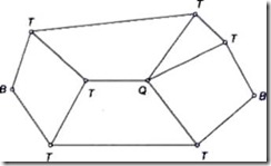
Ternary Joint: If 3 links square measure joined at an affiliation, it's called a ternary joint. it's thought-about admire 2 binary joints since fixing of anybody link constitutes 2 binary joints with every of the opposite 2 links. In Fig. 1.6 ternary links square measure mentioned as T.
Fig.1.6
Quaternary Joint: If four links are joined at an association, it's referred to as a quaternary joint. It thought-about corresponding to 3 binary joints since the fixing of anybody link constitutes 3 binary joints. Figure 1.6 shows one quaternary joint.
In general, if ‘n’ variety of links are connected at a joint, it's corresponding to (n-1) binary joints.
Key Takeaways:
Types of joints, binary, ternary and quaternary joints.
When one in each of the links of a kinematic chain is fastened, the chain is thought of as a mechanism. it's going to be used for transmittal or reworking motion e.g., engine indicators, typewriters, etc. A mechanism with four links is thought of as a straightforward mechanism, and also the mechanism with quite four links is thought of as a compound mechanism. higher than definitions, clearly shows that the mechanism may be a strained kinematic chain. If for a specific position of a link of the chain, the position of alternative links can't be foreseen, then it's referred to as associate degree at liberty kinematic chain and it's not a mechanism. Fig.1.7 shows a mechanism.
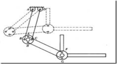
Figure.1.7. Mechanism
Key Takeaways:
Mechanism definition and examples of mechanism.
A machine may be a mechanism or assortment of mechanisms, that transmits the force from the supply of power to the resistance to be overcome, although all machines are mechanisms, all mechanism doesn't seem to be machined. A bit of thought can show that mechanism could also be thought to be a machine. Several instruments are mechanisms be machines, as a result of they are doing no helpful work nor do they remodel energy, e.g., mechanical clock, drafter(fig.1.8).
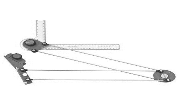 Figure.1.8. Drafter
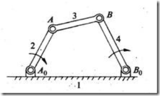
Figure.1.9. Machine
Key Takeaways:
Machine definition and its types and examples.
A free rigid body getting area will describe the subsequent freelance motions. change of location motions on any 3 reciprocally perpendicular axes x, y, and z, motility motions on these axes. Thus, a rigid body possesses six degrees of freedom. The association of a link with another imposes bound constraints on their relative motion. the number of restraints will ne'er be zero (the joint is disconnected) or six (joint becomes solid). Degrees of freedom of a try is outlined because of the variety of freelance relative motions, each change of location and motility, a try will have.
Degrees of freedom = 6 – no. of restraints. To find the number of degrees of freedom for a plane mechanism we've Associate in Nursing equation referred to as Grubler’s equation and is given by,
F = 3 (n – 1) – 2j1– j2
F = quality or a variety of degrees of freedom n = variety of links as well as the frame.
J1 = Joints with a single (one) degree of freedom. J2= Joints with 2 degrees of freedom. If F > 0, results in a mechanism with ‘F’ degrees of freedom. F = 0, leads to a statically determinate structure. F < 0, leads to a statically indeterminate structure. By taking the Associate in Nursing example of figure one.10, we can calculate the degrees of freedom simply. By the higher than given formula, F= 3(5-1)- 2*5= 2. So, there square measure two degrees of freedom within the mechanism shown in the figure.
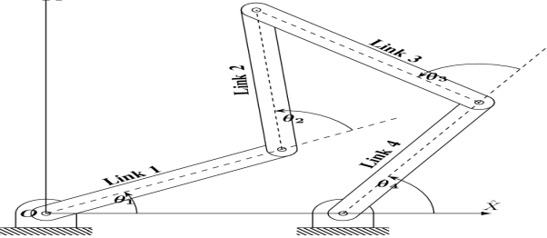
Figure.1.10. Five Bar Mechanism
Key Takeaways:
Degrees of freedom, Grubler’s equation F = 3 (n – 1) – 2j 1 – j 2, structure variety by degrees of freedom.
Mobility of a mechanism is one of all the prime issues in either the look or the analysis of a mechanism is that the variety of degrees of freedom, additionally renowned by quality of the mechanism. In different words, the quality of a machine is a variety of input parameters (usually paired variables) that have got to be controlled severally to bring the device into a selected position. Ignoring for the instant sure exceptions to be mentioned later, it's potential to see the quality of a mechanism directly from a count of the number of links, and therefore the variety and kinds of joints it includes. to develop this relationship, considering it before it gets connected, every link of a flat mechanism has 3 degrees of freedom, once moving relative to the fastened link. Not count, the fastened link, so associate n-link flat mechanism has 3(n-1) degrees of freedom before any of the joints square measure connected. Connecting a joint that has one degree of freedom, like a revolute combine, has the result of providing 2 constraints between the connected links. Now, once a 2 degree of freedom combine is connected, it provides one constraint. Once the constraint for all the joints square measure ablated from the entire freedoms of the unconnected links, we discover the ensuing quality of the connection mechanism. Once we use j1 to denote {the variety the amount the quantity} of single degrees of freedom and j2 for number of degrees of freedom for 2 pairs, the ensuing quality m of a flat link mechanism is given by,
M= 3(n-1)-2j1-j2
Figure 1.11 shows the Kutzbach criterion, for various mechanisms and that we will realize the quality consequently for all flat mechanisms.
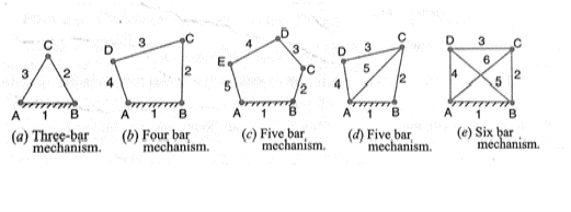 Figure.1.11 Application of Kutzbach Criterion
Key Takeaways:
Kutzbach criterion, Mobility based on mechanism= M= 3(n-1)-2j1-j2
a) Kinematic inversion of 4 bar chain
b) Slider crank chain or singe slider crank chain
c) Double slider crank chain
Key Takeaways:
Inversion of mechanisms, types of inversions.
Consider a four-bar mechanism as shown in the following figure:
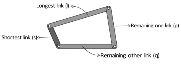
Figure.1.12. Grashof’s Law
s= shortest link
l= Longest link
p and q length of the other two links
By Grashof’s law, for at least one link to be capable of making a full revolution, the sum of the lengths of the shortest link and the largest link is less than or equal to the sum of the lengths of the other two links.
s + l ≤ p + q
The condition can be broken into two parts:
What happens if s+l > p+q?
For s+l>p+q, no link will be able to make a complete revolution, the mechanism so obtained is the triple rocker mechanism.
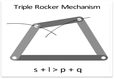
Figure.1.13. Triple Rocker Mechanism
In the triple rocker mechanism, one link is fixed while the other three oscillate.
Now, let us discuss the grashof condition. We broke the condition into two parts:
Case 1: The shortest link is adjacent to the first link.
The mechanism so obtained is the crank rocker mechanism.
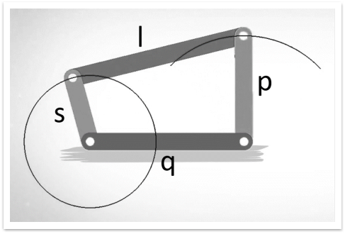
Figure.1.14. Crank Rocker Mechanism
In the crank rocker mechanism, the shortest link rotates fully while the other link pivoted to the fixed link oscillates.
Case 2: The shortest link is the fixed link.
The mechanism obtained in this case is known as a double crank mechanism.
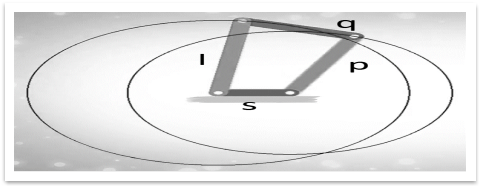
Figure.1.15. Double Crank Mechanism
In the double crank mechanism, both the links pivoted to the fixed link rotates fully.
Case 3: The shortest link is opposite to the fixed link
The mechanism obtained in this case is the double rocker mechanism.
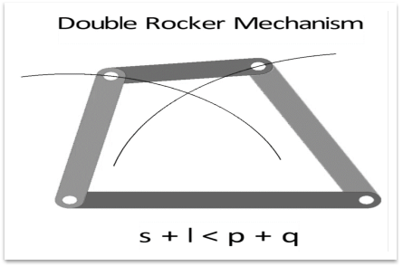
Figure.1.16. Double Rocker Mechanism
In the double rocker mechanism, both the links pivoted to the fixed link oscillate. The shortest link, which is the coupler, makes a full revolution.
2. s+l = p+q
Case 1: The length of the link is distinct.
Example: ‘s’ is 1 unit, ‘l’ is 4 units, ‘p’ is 2 units and q is 3 units. In this case, s+l= p+q= 5 units. In this case, all the inversions obtained are the same as in the case ‘s+l=p+q’= 5 units. In this case, all the inversions obtained are the same as in the case ‘s+l < p+q’.
Case 2: The length of the two links is the same.
Example: p=s=1 unit and l= 4 units. Now for ‘s+l= p+q’, q=l= 4 units. So we have two pair of equal length.
In this way link can be joined in two ways :
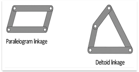
Figure.1.17. Parallelogram and Deltoid linkage
All the inversions are either crank rocker or double crank for this case.
Key Takeaways:
Grashof’s law, forumla= s + l ≤ p + q, double crank mechanism, double rocker mechanism, crank rocker mechanism, and all its conditions.
The kinematic chain may be a combination of 4 or additional kinematic pairs, specifying the relative motion between the links or components is unnatural. the best and therefore the basic kinematic chain may be a four-bar chain or curve cycle chain as shown in fig.1.18. It consists of 4 links, each of them forms a turning try at A, B, C, D. The four links are also of various lengths. currently, the speculation, of Grashof’s law clearly applies up here.
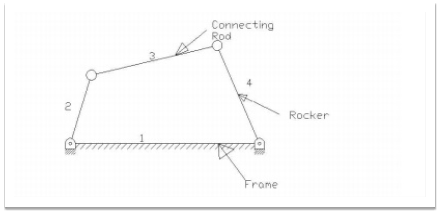
Figure.1.18. Four bar chain
A very vital thought in planning a mechanism is to make sure that the input crank makes a whole revolution relative to the opposite links. The mechanism during which no link makes a whole revolution won't be helpful. during a four-bar chain, one in each of the links especially the shortest link can create a whole revolution relative to the opposite 3 links, if it satisfies Grashof’s law. Such a link is understood as a crank or driver. In fig.1.18 (link 2) could be a crank. The link four makes a partial rotation or oscillates is understood as lever or rocker or follower and therefore the link three that connects crank and lever is named rod or coupling. The mounted link one is understood as a frame of the mechanism. once the crank is that the driver, the mechanism is reworking moves into periodical motion.
Inversions of four Bar Chain
Though there are many inversions of the four-bar chain, yet the following are important from the subject point of view:
A part of the mechanism of a beam engineer (additionally called crank and lever mechanisms) that consists of 4 links, is shown in figure.1.19 during this mechanism once the crank rotates regarding the fastened center A the lever oscillates regarding the fastened center. the top E of the lever CDE is connected to a connecting rod that reciprocates because of the rotation of the crank. In alternative words, this mechanism aims to convert motility into mutual motion.
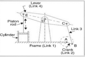
Figure.1.19 Beam Engine
2. Coupling rod of a locomotive ( Double crank Mechanism)
The mechanism of a coupling rod of a locomotive (additionally referred to as double crank mechanism) consists of 4 links as shown in figure.1.20. during this mechanism, the link AD and BC (having equal length) act as cranks and area unit connected to the several wheels. The link CD acts because the coupling rod and therefore the link AB is fastened to keep up a relentless center-to-center distance between them. This mechanism is supposed for sending rotation from one wheel to a different wheel.
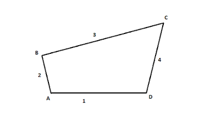
Figure.1.20 Coupling rod of a locomotive
3. Watt’s indicator mechanism (Double lever mechanism)
A watt’s indicator mechanism (conjointly called Watt’s line mechanism or double lever mechanism) consists of 4 links as shown in figure.1.21. The four links are fastened link at A, link metal, and link BFD. it should be noted BF and FD kind one link as a result of these 2 components don't have any relative motion between them. The link metal and BFD act as levers. The displacement of the link BFD act as levers. The displacement of the link BFD is directly proportional to the pressure of gas or steam that acts on the indicator plunger. On any little displacement of the mechanism, the tracer, the tracing purpose E at the tip of the link CF, traces at the tip of the link CF traces out more or less a line. The initial position of the mechanism is shown in figure.1.21 by full lines whereas the dotted lines show the position of the mechanism once the gas or steam pressure acts on the indicator plunger.
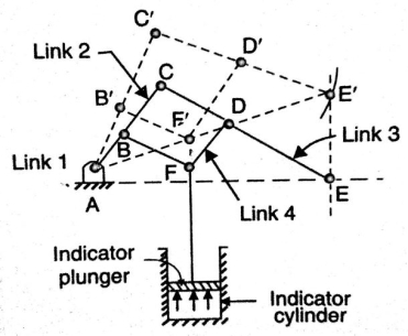
Figure.1.21 Watt’s Indicator Mechanism
Key Takeaways:
Four bar chain and its inversions, beam engine, coupling rod of a locomotive, watt’s indicator mechanism.
A single slider crank chain may be a modification of the fundamental four bar chain. It accommodates one slippery try and 3 turning pairs. it's typically found in a mutual external-combustion engine mechanism. this sort of mechanism converts motility into mutual motion and the other way around. during a single slider crank chain as shown in figure.1.22. the links one and a pair of, links a pair of and three, and links three and four type 3 turning pairs whereas link four and one forms a slippery pair. Link one corresponds to the frame of the engine, which is fastened. The link a pair of corresponds to the crank; link three corresponds to the rod and link corresponds to the crosshead. because the crank rotates, the crosshead reciprocates within the guides and so the piston reciprocates within the cylinder.

Figure.1.22. Single Slider Crank Chain
Inversions of Single Slider Crank Chain
We have seen within the previous article that one slider crank chain may be a four-link mechanism. we all know that by fixing, successively totally different links in an exceedingly kinematic chain, associate degree inversion is obtained and that we will obtain several mechanisms because of the links in an exceedingly kinematic chain. it's therefore obvious, that four bar inversions of one slider crank chain square measure doable. These inversions square measure found within the following mechanisms.
1.Pendulum pump or Bull Engine
In this mechanism, the inversion is obtained by fixing the cylinder or link four (i.e., slippy pair) as shown in fig.1.23. during this case, once the crank (link 2) rotates, the rod (link 3) oscillates a couple of pins pivoted to the fastened link four at A and therefore the piston hooked up to the connecting rod (link 1) reciprocates. The duplex pump that is employed to produce feed water to boilers has 2 pistons hooked up to link one, as shown in fig.1.23.
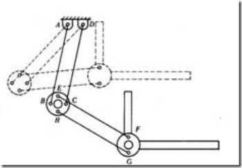
Figure.1.23 Pendulum Pump
2.Oscillating Cylinder Engine
The arrangement of oscillatory cylinder engine mechanism as shown in fig.1.24 is employed to convert reciprocal motion into motion. during this mechanism, the link three forming the turning try is fastened. Link three corresponds to the rod of a reciprocal external-combustion engine mechanism. once the crank (link 2) reciprocates and therefore the cylinder (link 4) oscillates concerning the pin pivoted to the fastened link at A.
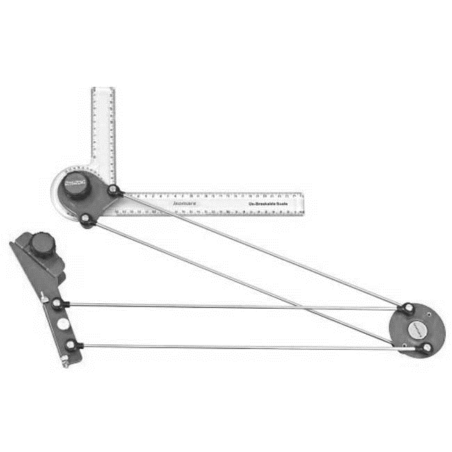
Figure.1.24 Oscillating Cylinder Engine
3. Rotary Internal Combustion Engine
Sometimes back, rotary burning engines were employed in aviation. however today turbine area unit employed in its place. It consists of seven cylinders in one plane and everyone revolves regarding fastened center D, as shown in fig.1.25 whereas the crank (link 2) is fastened. during this mechanism, once the rod (link 4) rotates, the piston (link 3) reciprocates within the cylinder forming link one.
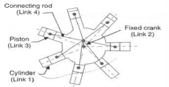
Figure.1.25 Rotary Internal Combustion Engine
4. Crank and Slotted Lever Mechanism
This mechanism is generally employed in shaping machines, slotting machines, and rotary burning engines. during this mechanism, the link AC (i.e., link 3) forming the turning try is fastened, as shown in fig.1.26. Link three corresponds to the rod of a reciprocal external-combustion engine. The driving crank CB revolves with uniform angular speed regarding the fastened center C. A slippy block connected to the crankpin at B slides on the slotted bar AP and so causes AP to oscillate regarding the pivoted purpose A. a brief link PR transmits the motion from AP to the ram that carries the tool and reciprocates on the road of stroke R1R2. the road of stroke of the ram (i.e., R1R2) is perpendicular to AC made.
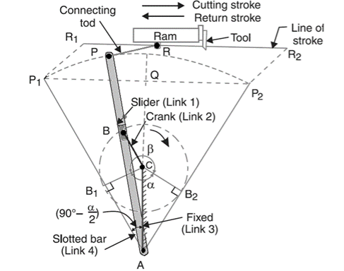
Figure.1.26. Crank and Slotted Lever Quick Return Mechanism
In the extreme position, AP1 and AP2 area unit tangential to the circle and therefore the cutlery is at the top of the stroke. The forward or cutting stroke happens once the crank rotates from the position CB1 to CB2 (or through associate angle β) within the dextrorotatory direction. Since the crank has uniform angular speed, therefore,
Since the tool travels a distance of R1R2 during cutting and return stroke, therefore travel of the tool or length of stroke
= R1R2 = P1P2 = 2P1Q = 2AP1 sin(P1AQ)
= 2 AP1 sin (90 – α/2) = 2 AP cos α/2
= 2 AP cos α/2
= 2 AP × 
5. Whitworth Quick Return Motion Mechanism
This mechanism is generally employed in shaping and slotting mechanism. during this mechanism, the link CD (link 2) forming the turning try is fastened. As shown in figure one.27. The link a pair of corresponds to a crank during a reciprocatory external-combustion engine. The driving crank CA (link 3) rotates at a homogenous angular speed. The slider (link 4) hooked up to the crankpin at A slides on the slotted bar PA (link 1) that oscillates at a pivoted purpose D. The rod PR carries the ram at R to that a cutting implement is fastened. The motion of the tool is forced on the road RD made i.e., on a line passing through D and perpendicular to CD.
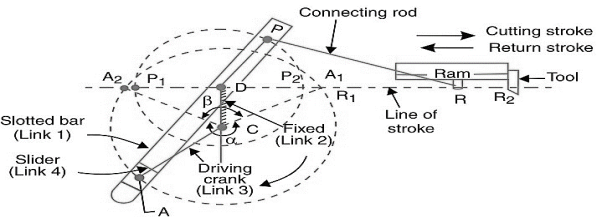 Figure.1.27. Whitworth quick return motion mechanism
A little thought can show that the time taken throughout the left to right movement of the ram (i.e., throughout forward or cutting stroke) is quite the time taken throughout the comeback stroke). In different words, the mean speed of the ram throughout the cutting stroke is a smaller amount than the mean speed of the ram throughout the cutting and come backstroke is given by,
 =
=  =
= 
Key Takeaways:
Inversions of single slider crank chain and its types, crank and slotted lever mechanism, pendulum pump, oscillating cylinder engine, rotary combustion engine, whitworth quick return mechanism, the ratio of time of cutting and return stroke in metal cutting for quick return mechanisms.
Inversions of Double Slider Crank Chain
It is an Associate in Nursing instrument used for drawing ellipses. This inversion is obtained by fixing the slotted plate (link 4) as shown in fig.1.28. The fastened plate or link four has 2 straight grooves cut in it, at right angles to every difference. Link one and link three square measure referred to as sliders and type slippery pairs with link four. The link AB (link 2) may be a bar that forms turning combine with links one and three. When the links one and three slides on their grooves, Associate in Nursing purpose on the link a pair of like P traces out an oval on the surface of link four, as shown as fig.1.28. a bit of thought can show that AP and BP square measure the semi-major and semi-axis of the oval severally. this could be proved as follows:
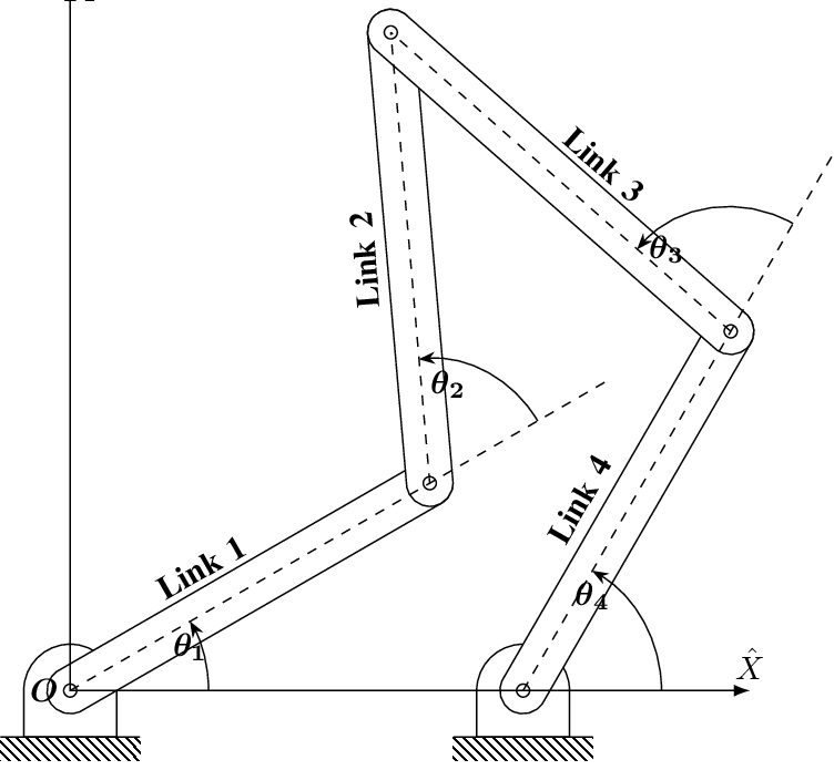
Figure.1.28. Elliptical Trammels
x= PQ = AP cos  and y= PR = BP sin
 = cos
= cos ;
;  = sin
= sin 
Squaring and adding both sides,
 +
+  =1
=1
Hence traced by point P is an ellipse.
2. Scotch Yoke Mechanism
This mechanism is employed for changing movement into reciprocatory motion. The inversion is obtained by fixing either link one or link three. In fig1.29 link one is mounted whereas link two (which corresponds to the crank) rotates regarding B as center, the link four (which corresponds to a frame) reciprocates. The mounted link guides the frame.

Figure.1.29 Scotch Yoke Mechanism
3. Oldham’s Coupling
An Oldham’s coupling is employed for connecting 2 parallel shafts whose axes are at a little distance apart. The shafts are coupled in such a way that if one shaft rotates, the opposite shaft conjointly rotates at an identical speed. The inversion is obtained by fixing link two as shown in fig.1.29 (a). The shafts to be connected have 2 flanges (link one and link 3) stiffly mounted at either end by formation. Link one and link three types turning combine with link two. These flanges have diametrical slots cut in their inner faces as shown in fig.1.30(c). The tongues on link four closely match into {the 2} slots within the two flanges (link one and link 3). Link four will slide or reciprocate within the slots within the flanges. When the driving shaft A is turned, projection C (link 1) causes the intermediate piece (link 4) to rotate at an identical angle through that projection is turned and it rotates the projection D speed at each instant.

(a) (b) (c)
Figure.1.30. Oldham’s Coupling
Key Takeaways:
Double slider crank chain and its inversions, Elliptical trammels, scotch yoke
the mechanism, Oldham's coupling.
Generally, a better combine may be a constraint that needs a curve or surface within the moving body to keep up contact with a curve or surface within the mounted body. For, example the contact between the cam and its follower may be a higher combine known as a cam joint. In alternative words, once the 2 kinematic links area unit connected in such some way that they need a line or purpose contact between the 2 links it's known as higher pair.
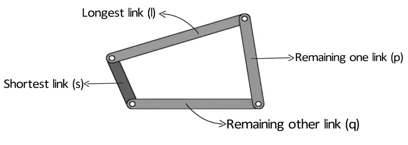
Figure.1.31. Higher Pair Mechanism
Key Takeaways:
Higher pair mechanism such as link and follower mechanism. Point of contact tangential rotation.
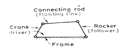
Figure.1.32. Equivalent Mechanisms
The cases of equivalent linkages are:
Figure.1.32 shows slippy pairs in situ of turning pairs. Link 4 i.e., rocker length is magnified to time so D lies at the time. currently with the rotation of the crank purpose of contact can have linear motion perpendicular to the axis of link four. equally turning pairs is replaced by slippy pairs by providing slider with guides at B. just in case the axis of 2 slippy pairs in one line or parallel the 2 sliders in conjunction with link three-act mutually link with no relative motion among these links. Thus, so as to switch 2 turnings trys during a linkage with slippy pairs by fixing a slider to any of the 2 links forming a pair.
2. Spring in place of Turning pairs
The action of a spring is to elongate or shorten because it becomes in tension or compression. the same variation long is accomplished by 2 binary links joined by a turning try. In figure. 1.33 the length AB varies as OB touched away or towards purpose A. Figure 1.33 shows a six -link mechanism within which link four and five are replaced by a spring.
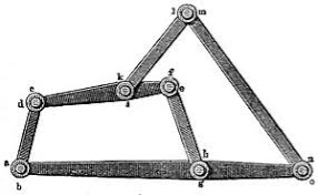
Figure.1.33. Six link Mechanism
3. Cam in place of Turning pairs
A cam pair has 2 degrees of freedom. For linkages with one degree of freedom, application of grubler’s equation yields.
P1 = 3N-5 /2
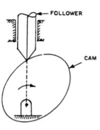
Figure.1.34. Cam replaced with turning pair
Key Takeaways:
Equivalent linkages such as spring in place of turning pairs, cam in place of turning pairs.
Reference Books:
2. Bevan T, “Theory of Machines”, Third Edition, Longman Publication |
3. Paul E. Sandin, “Robot Mechanisms and Mechanical Devices Illustrated”, Tata McGraw Hill Publication |
4. Ghosh Malik, “Theory of Mechanism and Machines”, East-West Pvt. Ltd.
5. M.P. Groover, “Automation, production systems and computer-integrated manufacturing”, Prentice-Hall of India Pvt. Ltd
|
|
|
|
