Unit - 4
Fluid Dynamics


Where,
 = mass density of the fluid
u, v & w= Components of velocity of flow entering the three faces of the parallelepiped
Bx – - v [
- v [ +
+
By –  - v [
- v [ +
+
Bz –  - v [
- v [ +
+
Where,
B be the body force per unit mass of fluid having components Bx, By &Bz in X, Y, Z direction s respectively
 = mass density of the fluid
u, v & w= Components of velocity of flow entering the three faces of the parallelepiped
v= kinematic viscosity
Consider steady flow of an ideal fluid along the shown tube.
Separate out a small element of fluid of cross- sectional area dA and length ds from stream tube as a Freebody from the during fluid.
Fig. shows such a small elements LM of fluid of cross Section area dA and length ds.
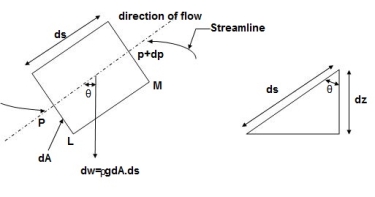
Let, p= Pressure of the elements at L
p+dp = Pressure on the element at M, and
V=Velocity of the fluid element.
The external forces tending to accelerate the fluid elements in the direction of streamline are as follows:
= - .g.dA.ds.cos
=- .g.dA.ds (dz/ds) (: Cos
 = dz/ds)
= - .g. dA.dz
Mass flow of the fluid element =  .dA.ds
The Acceleration of the fluid element
a = dv/dt = dv/ds*ds/dt = v.dv/ds
Now, according to Newton’s second law of motion, force= mass x acceleration.
:. –dp. dA. - .g. dA.dz=
  .dA.dsx v.dv/ds
Dividing both sides by  .dA, we get
-dp/ - g.dz= v.dv
Or dp/ +v. dv+g.dz=0
This is the required Euler’s equation for motion.
Integrating the Euler’s equation of motion, we get
1/
p/ +v2/2+gz = constant
dividing by g, we get
p/ g +v2/2g +z = constant
p/w+v2/2g +z = constant
or in other words,  +
+
which proves Bernoulli’s equation.
Modified Bernoulli’s theorem:
Simplified formula for converting velocity difference obtained by spectral Doppler to instantaneous pressure gradient.
This clinical equation has been derived from the more complex Bernoulli equation by assuming that viscous losses and acceleration effects are negligible and by using an approximation for the constant that relates to the mass density of blood, a conversion factor for measurement units.
In addition, the simplified Bernoulli equation assumes that the proximal velocity can be ignored, a reasonable assumption when velocity is <1 m/s because squaring a number <1 makes it even smaller. When the proximal velocity (V1) is over >1.5 m/s or the aortic velocity (V2) is <3.0 m/s, the proximal velocity should be included in the Bernoulli equation.
∆P =P2-P1 = 4(V22 – V12)
Variable Definition
V1 Proximal velocity (m/s)
V2 Distal velocity (m/s)
ΔP Instantaneous pressure gradient (mmHg)
In general, pressure is a measure of the force exerted per unit area on the boundaries of a substance. In fluid dynamics and aerodynamics, stagnation pressure (or pitot pressure or total pressure) is the static pressure at a stagnation point in a fluid flow. At a stagnation point the fluid velocity is zero and all kinetic energy has been converted into pressure energy (isentropically). This effect is widely used in aerodynamics (velocity measurement or ram-air intake).
Stagnation pressure is equal to the sum of the free-stream dynamic pressure and free-stream static pressure.

Static pressure and dynamic pressure are terms of Bernoulli’s equation:

Bernoulli Theorem – Equation
The Bernoulli’s effect causes the lowering of fluid pressure (static pressure – p) in regions where the flow velocity is increased. This lowering of pressure in a constriction of a flow path may seem counterintuitive, but seems less so when you consider pressure to be energy density. In the high velocity flow through the constriction, kinetic energy (dynamic pressure – ½.ρ.v2) must increase at the expense of pressure energy (static pressure – p).
The simplified form of Bernoulli’s equation can be summarized in the following memorable word equation:
static pressure + dynamic pressure = total pressure (stagnation pressure)
Total and dynamic pressure are not pressures in the usual sense – they cannot be measured using an aneroid, Bourdon tube or mercury column.
Stagnation pressure is sometimes referred to as pitot pressure because it is measured using a pitot tube. A Pitot tube is a pressure measurement instrument used to measure fluid flow velocity. Velocity can be determined using the following formula:

where:
u is flow velocity to be measured in m/s,
ps is stagnation or total pressure in Pa,
pt is static pressure in Pa,
ρ is fluid density in kg/m3.
In fluid dynamics, stagnation pressure (or pitot pressure) is the static pressure at a stagnation point in a fluid flow.] At a stagnation point the fluid velocity is zero. In an incompressible flow, stagnation pressure is equal to the sum of the free-stream static pressure and the free-stream dynamic pressure.
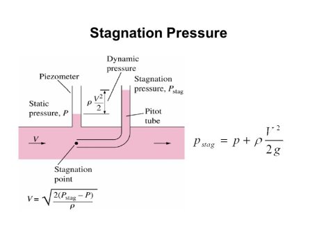
Stagnation pressure is sometimes referred to as pitot pressure because it is measured using a pitot tube.
The concept of hydraulic gradient line and total energy line is quite useful in the study of flow of fluid in pipes.
Total energy Line (T.E.L. or E.G.L)
Total head = 
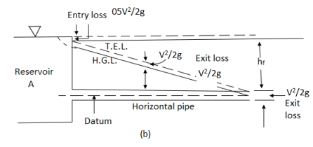
Hydraulic gradient Line (H.G.L)


Bernoulli’s equation is applied is all problems of incompressible fluid flow where energy considerations are involved, but we shall consider its applications to the following measuring devices:
i) Venturimeter
ii) Pitot- tube
iii) Sub-merged orifice
iv) Orifice meters
v) V Notch
4.7.1 Venturimeter
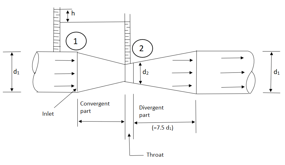
A venturimeter is a device used for measuring the rate of a flow of a fluid flowing through a pipe it consists of three parts:
i) A short converging part, ii) Throat, and (iii)Diverging Part

It is based on the principle of Bernoulli’s equation.
Expression for Rate of flow through venturimeter
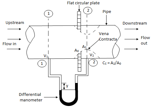
Consider a venturimeter fitted in a horizontal pipe through which a fluid is following as shown in fig.
Let d1 = diameter at inlet or at section (1)
P1= pressure at section (1)
V1 = velocity of fluid at section (1)
a1= area of section (1) =π/4. d2
and d2, P2, V2, a2 are corresponding values at section (2)
Applying Bernoulli’s equation at section (1) and (2) we get
 +
+
As pipe is horizontal hence z1 = z2


But  is the difference of pressure heads at section land 2 and it is equal to h
 =h
=h
Substituting this value of  in the above eqn we get.
 h =
h =  …………. (1)
Now applying continuity equation at section 1 and 2
a1 v1 = a2 v2
 v1 =
v1 = 
Substituting this value of v1 in equation 1


 =
= 
Q = a2v2
=a2 
= 
Above equation gives the discharge under ideal conditions and is called, theoretical discharge Actual discharge will be less than theoretical discharge.
Qact =
Where Cd = co-efficient of venturimeter and its value is less than 1.
2.7.2 Orifice Meters or Orifice plate.

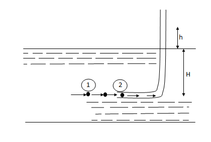
2.7.3 Pitot-tube: -
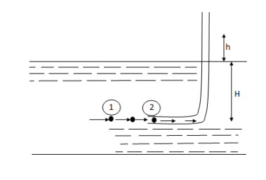
P1= intensity of pressure at point (1)
V1 = velocity of flow at (1)
P2 = pressure at point (2)
V2 = velocity at point (2), which is zero
H = depth of tube in the liquid.
h = rise of liquid in the tube above the fire Surface
Applying Bernoulli’s equation at points (1) and (2)
We get
 +
+
But Z1 = Z2 as points (1) and (2) are the same line and V2 =0
 = pressure Lead at (1) = H
 = pressure head at (2) = (h+H)
Substituting these values, we get
H+  = (h+H)
:. h=  or V1 =
This is theoretical velocity.
Actual velocity is gives by (V1) act= Cv
Where Cv= Co-efficient of pitot-tube
:. Velocity at any point V= Cv
2.7.4 Static pitot tube
4.8 Introduction to Coriolis flow meter
Referencing the figure on the right, a particle (dm) travels at a velocity (V) inside a tube (T) in a Coriolis meter. The tube is rotating about a fixed point (P), and the particle is at a distance of one radius (R) from the fixed point. The particle moves with angular velocity (w) under two components of acceleration, a centripetal acceleration directed toward P and a Coriolis acceleration acting at right angles to ar:
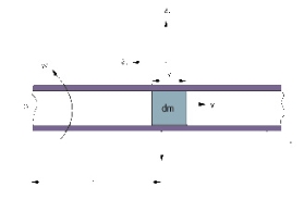
ar (centripetal) = w2r
at (Coriolis) = 2wv
In order to impart the Coriolis acceleration (at) to the fluid particle, a force of at (dm) has to generated by the tube. The fluid particle reacts to this force with an equal and opposite Coriolis force:
Fc = at(dm) = 2wv(dm)
Then, if the process fluid has density D and is flowing at constant speed inside a rotating tube of cross-sectional area A, a segment of the tube of length x will experience a Coriolis force of magnitude:
Fc = 2wvDAx
Because the mass flowrate is dm = DvA, the Coriolis force Fc = 2w(dm)x and, finally:
Mass Flow = Fc/(2wx)
This is how measurement of the Coriolis force exerted by the flowing fluid on the rotating tube can provide an indication of mass flowrate. Naturally, rotating a tube is not practical when building a commercial Coriolis mass flow meter, but oscillating or vibrating the tube can achieve the same effect. Coriolis flow meters can measure flow through the tube in either the forward or reverse directions.
In most designs, the tube is anchored at two points and vibrated between these anchors.
This configuration can be envisioned as vibrating a spring and mass assembly. Once placed in motion, a spring and mass assembly will vibrate at its resonant frequency, which is a function of the mass of that assembly. This resonant frequency is selected because the smallest driving force is needed to keep the filled tube in constant vibration.
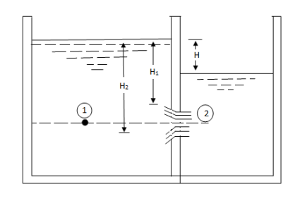
H1 = Height of water above the top of the orifice on the upstream side,
H2 = Height of water above the top of the orifice on the downstream side,
H = Difference in water level.
b = Width of orifice,
Cd = Co-efficient of discharge.
Height of water above the center of the orifice on the upstream side,
= 
Height of water above the center of the orifice on the downstream side,
= 
Applying Bernoulli’s eqn. at 1 & 2


 V1 is negligible.


V2 = 
Area of orifice = b (H2 – H1)
Q = Cd x b (H2 – H1) x 
Flow through sharp edged circular orifice discharging free
An orifice is an opening in the wall or base of a vessel through which the fluid flows. The top edge of the orifice is always below the free surface.
Flow through an orifice
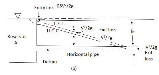
Considering points 1 and 2 as shown in figure and applying Bernoulli’s theorem, we have


Further, if the cross-sectional area of the tank is very large, the liquid at point 1 is practically standstill and hence V1 = 0


V notch
Let H = head of water over apex above the notch
 = Angle of notch
Cd= Co-efficient of discharge.
Consider a horizontal strip of water of thickness dh at depth h from water surface as shown in fig.

AC = H – h
Width of strip = AB = 2AC = 2H – h 
Area of strip = 2 (H – h) 
Theoretical velocity of water through strip = 
Discharge through strip dQ = Cd x Area of strip x Velocity
= Cdx 2 (H – h)  x
x 
= 2 Cdx( H – h)  x
x 
Total discharge Q = 
= 
= 
= 
= 
= 

Numerical:
1. An oil of sp.gr 0.8 is flowing through a venturimeter having inlet diameter 20 cm & throat diameter 10cm. The oil mercury differential nanometers show a reading 25 cm. calculate the discharge of oil through the horizontal venturimeter Take cd = 0.98
Given
S1= 0.8
Sm =13.6
d1=0.2m
d2=0.1m
x=0.25m
cd=0.98
A1 = π/4*d12 = π/4*0.22 = 0.0314 m2
A2 = π/4*d22= π/4* 0.12 = 7.85*10-3m2
 = 4m
= 4m
Q = 
= 
=0.0705 m3/sec
2. The inlet & throat diameters of horizontal venturimeter are 30cm & 10cm respectively. The liquid flowing throat the meter is water, the pressure intensity at inlet is 13.734 N/cm2 while the vacuum pressure head at the throat is 37cm of mercury. Find rate of flow Assume that 4%of the differential head is lost between the inlet & throat. Find also the value Cd for the venturimeter.
Given
d1 =0.3m
d2= 0.1m
p1=13.734 x10⁴N/m2
Vacuum pressure head = - 0.37m of Hg
hf = 4 % of h = 0.04h
A1= x d12 =
 =0.0706m2
A2=  x d22=
 =
=
P2 = w *Vacuum pressure head
= (13.6 x 9810) x -0.37
= - 49.37 x10³ N/m2
h=  =
=
= 19.03 m
hf= 0.04h = 0.04 x 19.032 = 0.7613m
Cd =  =
= = 0.98
Q=
= 
= 0.149 m3/sec
3. A 30cm x 15cm venturimeter is provided a vertical pipe line carrying oil of specific gravity 0.9, The flow being upwards. The different in elevation of the venturimeter is 30cm. The differential U tube mercury manometer shows a gauge deflection of 25cm calculate i) the discharge ii) pressure difference between the entrance section throat section. Take Cd = 0.98
Given
d1 = 0.3m
d2 = 0.15m
SL =0.9
Z1=0
Z2 = 0.3 M
X = 0.25 M
A1 = π/4 * d12 = π/4*0.32 = 0.0706m2
A2 = π/4 * d22 = π/4*0.152 = 0.0176m2
h= - 1) = 0.25 (
Q =
= 
=0.149 m3/sec
h=  +(z1-z2)
3.53 =  +(0 - 0.3)
P1-P2 =33.81 x 10³ N/m2
4. Find the discharge of water flowing through a pipe 30cm diameter placed in on inclined position where a venturimeter is inserted, having a throat diameter of 15 cm. The difference of pressure between the main & throat is measured by a sp.gr 0.6 in an inverted tube which gives a reading of 30 cm. The loss of head between the main & threat 0.2 times the kinetic head of the pipe.
Given
d1 = 0.3 m
d2 = 0.15m
Sm = 0.6
x= 0.3m
hL=0.2 
A1 =  * d12 =
  * 0.32 = 0.0706m2
A2 =  *d22 =
  * 0.152 = 0.0176 m2
h = x [1-  ] = 0.3 [1-
  ] = 0.12m
Applying Bernoulli’s eqn. at section 1& 2
:.  +
+  + Z1 =
 +
+ + Z2+ hL
( -
-  ) + (Z1-Z2) =
 -
-  + hL
+ hL
Applying Continuity eqn. at section (1) & (2)
A1V1 =A1 V2
 = V2
= V2
 = V2
= V2
:. V2 = 4V1
:. ( -
-  ) + (Z1-Z2) =
 -
-  +
+ 
:. h = 
:. 0.12 = 
:.V1 = 0.393m/s
:.Q = A1 V1
= 0.0706 x 0.393
= 0.0277 m3/sec
Entrance region theory
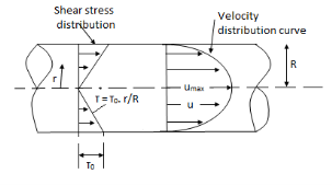
Velocity and shear Stress distribution for laminar flow through pipe
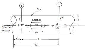
Fig: Shows a horizontal circular pipe of radius R, having laminar flow of fluid through it.
Consider a small concentric cylinder of radius r and length dx as a free body.
If  is the shear stress, the shear force F is given by
F =  x 2
x 2  r x dx
Let P be the intensity of pressure at left end and the intensity of pressure at the right end be (
Thus, the force acting on the fluid element are:
i) the shear force,  x 2
x 2 r x dx on the surface of fluid element.
ii) The pressure force, P x  on the left end.
iii) The pressure force, ( on the right end.
For steady flow, the net force on the cylinder must be zero.
 [ p x
[ p x  - (
- ( ] –
] – 
 -
-  -
-

Shear stress is zero at the center of pipe (r = 0) and maximum at the pipe wall given by
 (
( )
)
From Newton’s Law of viscosity.

In this equation, the distance y is measured from the boundary. The radial distance r is related to distance y by the relation.
y = R-r ordy = -dr

Comparing two values of 
 =
= 
 du =
du =  (
( )r.dr
)r.dr
Integrating the above equation w. r. t. ‘r’ we get
 u =
u =  .
.  r2 + C --------------- (ii)
Where C is the constant of integration and its value is obtained from the boundary conditions.
At r = R, u = 0
 0 =
0 =  .
.  R2 + Cor C =
  .
.  R2
R2
Substituting this value of C in eqn. (ii) we get,
 u =
u =  .
.  r2
r2 .
.  R2
R2
 u = -
u = -  .
.  (R2 – r2)
Shows that velocity distribution curve is a parabola.
The maximum velocity occurs, at the center and is given by.
 umax = -
  R2
R2
Flow of viscous fluid between two parallel plates when one plate is moving & other of Rest – Coutte flow
Consider laminar flow between two parallel flat plates located at a distance b apart such that lower plate is at rest & the upper plates moves uniformly with a constant velocity U as shown in fig.
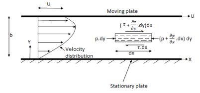
A small rectangular element of fluid of length dx, thickness dy & unit width is
Considered as a free body.
The forces acting on the fluid element are
1) The pressure force p dy x 1 on left end
2) The pressure force (p + . dx) dy x1 on the right end.
3) The shear force 
4) The shear force [ . dy] dx x 1 on the surface.
For steady & uniform flow the resultant force in the direction of flow is zero.
p. dy – (p +  . dx) dy –
  + (
+ ( +
+ . dy) dx = 0
- dx. dy +
  dy. dx = 0
Dividing by the volume of element dx. dy, we get
 =
=  -------------------(1)
Above equation shows the interdependence of shear & pressure gradients
According to Newton’s law of viscosity for laminar flow the shear stress.
 =
=  .
. 
put in equation (1) we get,
 =
= 
Integrating above equation twine w.r.t. y
u =  y2 + C1 y + C2 -------------(2)
At y = 0, u = 0 & at y = b, u = U
We get C2 = 0 & C1 =  -
-  (
( ) b
) b
Put values of C1& C2 in eqn. (2)
u =  y -
y -  (by – y2)
q =  =
=  (by – y2)] dy
U.  -
- 
The distribution of shear stress across any section may be determined by using
Newton’s Law of viscosity
 = u.
= u.  =
=  [
[ -
-  (
( ) (b – 2y)]
=  -
-  (b – 2y)
Both Plates at Rest:
In this case the equations for velocity, discharge q and the shear can be obtained from similar equation for generalizes Coutte flow by putting U = 0
Thus, for flow between two stationary parallel plates.
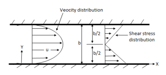
u = -  .
.  (by – y2)
Discharge per unit width,
q =  .
. 
Shear stress  .
.  (b –2y)
Velocity Distribution for turbulent flow in smooth pipes.
The velocity distribution for turbulent flow in smooth or rough pipe is given by equation as
u = logey + c
It may be seen that at y = 0, the velocity u at wall is + 
This means that velocity u is positive at some distance away from the wall and -  (minus Infinity) at the wall.
Hence at some finite distance from wall the velocity will be equal to zero.
Let this distance from pipe wall is y
Now, the constant C is determined from the boundary condition.
at y = y, u = 0.
Hence above equation become as
0 =  logey’+ c
c = -  logey’
Substituting the value of c in above eqn.
u =  logey -
  logey’
=  loge
loge
Substituting the value of K = 0.4, we get
u =  loge
loge loge
loge
 =
=  log10
log10
 =
=  log10
log10 ---------(i)
From Nikuradse’s experiment the value of y’ is given as
y’ = 
Where  =
=  , where
  = Kinematic viscosity of fluid.
y =  x
x  =
= 
Substituting this value of y’ in equation (i), we obtain
 = 5.75 log10 (
  )
)
= 5.75 log10 (  ) = 5.75 log10 (
= 5.75 log10 + 5.75 log10 9.259
= 5.75 log10 + 5.55
The above equation is known as Karman Prandtl equation.
Velocity Distribution for Turbulent flow in Rough Types.
In case of rough boundaries, the thickness of Laminar sub – layer is very small.
The surface irregularities are above the laminar sub- layer and hence the laminar sub layer is completely destroyed.
Thus y’ can be considered proportional to the height of protrusions k.
Nikuradse’s experiment shows the value of y’ for pipes coated with uniform sand (rough pipes) as
y’ = 
Substituting this value of y’ in equation
 = 5.75 log (y/y’)
 = 5.75 log10 (
 ) = 5.75 [ log10 (y/k) x 30]
= 5.75 log10 (y/k) + 5.75 log10 (30.0)
= 5.75 log10 (y/k) + 8.5
References:
1. Kundu, Cohen, Dowling, “Fluid Mechanics”, Elsevier India
2. Chaim Gutfinger David Pnueli, “Fluid Mechanics” Cambridge University press.
3. Edward Shaughnessy, Ira Katz James Schaffer, “Introduction to Fluid Mechanics”, Oxford University Press

