Unit - 1
Introduction to Mechatronics, Sensors & Actuators
Definition
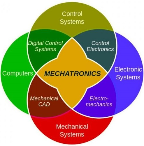
It is an interdisplinary area of engineering that combines mechanical, electronic and computer engineering.
Mechatronics system
Mechatronics integrates various technologies involving
- Sensor and measurement systems.
- Drive and actuation system. (Mechanical/pneumatics/Hydraulics)
- Controlling system
Objective of Mechatronics
- It integrates mechanical system with electronic and computer systems.
- It improves efficiency of the system
- It reduces cost of production
- To improve precision and accuracy
- Costumer satisfaction and comfort
Advantages
- High level of integration
- High degree flexibility
- High productivity
- Product produced are cost effective
Disadvantages
- Initial cost is very high
- Repair and maintenance is complex
- Replacement of system is difficult
- Require qualified employees.
Elements of Mechatronics system
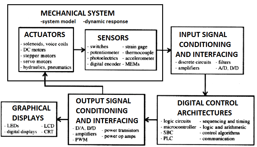
Fig 1 Elements of Mechatronics
- Sensors.
- Actuators (Hydraulics, Pneumatics)
- PLC, Micro controllers.
- Electrical Motors.
- Mechanical Couplings, Assembly & Gears.
- Control Panel.
Mechatronics brings together the technology of sensors and measurements systems, embedded microprocessor systems, actuators and engineering design. The following are examples of mechatronic systems and illustrate how microprocessor- based systems have been able not only to carry out tasks that
Previously were done ‘mechanically’ but also to do tasks that were not easily automated before.
The digital camera and autofocus
A digital camera is likely to have an autofocus control system. A basic system used with less expensive cameras is an open-loop system. When the photographer presses the shutter button, a transducer on the front of the camera sends pulses of infrared (IR) light towards the subject of the photograph. The infrared pulses bounce off the subject and are reflected back to the camera where the same transducer picks them up. For each metre the subject is distant from the camera, the round-trip is about 6 ms. The time difference between the output and return pulses is detected and fed to a microprocessor. This has a set of values stored in its memory and so gives an output which rotates the lens housing and moves the lens to a position where the object is in focus. This type of autofocus can only be used for distances up to about 10 m as the returning infrared pulses are too weak at greater distances. Thus for greater distances the microprocessor gives an output which moves the lens to an infinity setting.
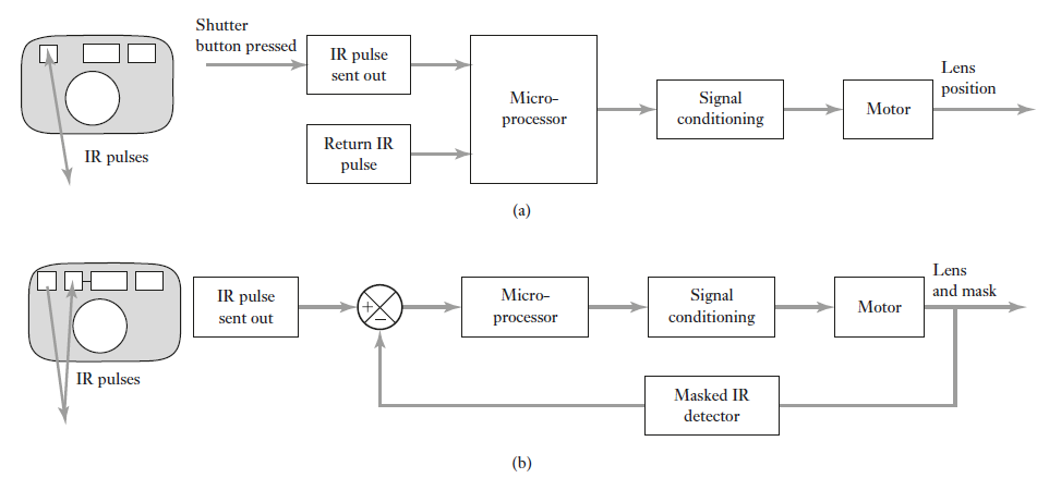
Fig 2 Autofocus
A system used with more expensive cameras involves triangulation. Pulses of infrared radiation are sent out and the reflected pulses are detected, not by the same transducer that was responsible for the transmission, but by another transducer. However, initially this transducer has a mask across it. The microprocessor thus gives an output which causes the lens to move and simultaneously the mask to move across the transducer. The mask contains a slot which is moved across the face of the transducer. The movement of the lens and the slot continues until the returning pulses are able to pass through the slot and impact on the transducer. There is then an output from the transducer which leads the microprocessor to stop the movement of the lens, and so give the in-focus position.
The engine management system
The engine management system of an automobile is responsible for managing the ignition and fuelling requirements of the engine. With a four-stroke internal combustion engine there are several cylinders, each of which has a piston connected to a common crankshaft and each of which carries out a four-stroke sequence of operations. When the piston moves down a valve opens and the air–fuel mixture is drawn into the cylinder. When the piston moves up again the valve closes and the air–fuel mixture is compressed. When the piston is near the top of the cylinder the spark plug ignites the mixture with a resulting expansion of the hot gases. This expansion causes the piston to move back down again and so the cycle is repeated. The pistons of each cylinder are connected to a common crankshaft and their power strokes occur at different times so that there is continuous power for rotating the crankshaft. The power and speed of the engine are controlled by varying the ignition timing and the air–fuel mixture. With modern automobile engines this is done by a microprocessor.
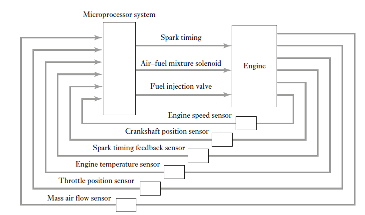
Fig 3 Elements of an engine management system.
Figure shows the basic elements of a microprocessor control system. For ignition timing, the crankshaft drives a distributor which makes electrical contacts for each spark plug in turn and a timing wheel. This timing wheel generates pulses to indicate the crankshaft position. The microprocessor then adjusts the timing at which high-voltage pulses are sent to the distributor so they occur at the ‘right’ moments of time. To control the amount of air–fuel mixture entering a cylinder during the intake strokes, the microprocessor varies the time for which a solenoid is activated to open the intake valve on the basis of inputs received of the engine temperature and the throttle position. The amount of fuel to be injected into the air stream can be determined by an input from a sensor of the mass rate of air flow, or computed from other measurements, and the microprocessor then gives an output to control a fuel injection valve. Note that the above is a very simplistic indication of engine management.
Key takeaway
They are used in digital cameras and autofocus. In engine management system.
To choose the perfect measurement system, we have to know the measurement characteristics of system
Static characteristics
The performance criteria for the measurement of quantities is remain constant or vary slowly.
Dynamic Characteristics
The relationship between system input and output of measured quantities varies rapidly
Terminology
- Span and Range
- Error
- Repeatedly
- Reliability
- Accuracy
- Hysteresis
- Sensitivity
- Resolution
- Calibration
Span and Range
Range of system is the lowest and the highest value of system
e.g Range-30°c to -80°c
The full extent of something from end to end; the amount of space that something covers.
e.g Span 80°c – (- 30°c) = 110°c
Error
A measure of the estimated difference between the observed or calculated value of a quantity and its true value.
Error = Measured value – True value
Repeatability
The repeatability of a robot might be defined as its ability to achieve repetition of the same task.
Reliability
The ability of an apparatus, machine, or system to consistently perform its intended or required function or mission, on demand and without degradation or failure.
Accuracy
Accuracy refers to the closeness of a measured value to a standard or known value.
Hysteresis
In hysteresis the output of a system depends not only on its input, but also on its history of past inputs.
Caused by electrical or mechanical system
- Magnetization
- Thermal properties
- Loose linkages
Sensitivity
It is an absolute quantity, the smallest absolute amount of change that can be detected by a measurement.
Resolution
The act of distinguishing between two close, but not identical objects, or, when taking a measurement, between two close values of the property measured.
Calibration
Calibration is the setting or correcting of a measuring device or base level, usually by adjusting it to match or conform to a dependably known and unvarying measure.
Key takeaway
Static characteristics
The performance criteria for the measurement of quantities is remain constant or vary slowly.
Dynamic Characteristics
The relationship between system input and output of measured quantities varies rapidly
Types of Sensors
- Position sensor – Potentiometer, LVDT,Incremental encoder
- Proximity sensor –Optical, Inductiveand Capacitive
- Temperature – RTD , Thermocouples
- Force/Pressure sensors – Strain gauges
- Forcesensors – Electromagnetic
Definition
The vital part of a mechatronics system is the sensing of physical parameters either discrete or continuous.
Position sensors
Potentiometer
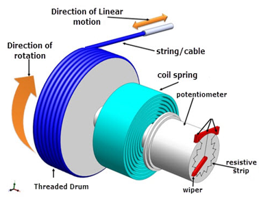
Fig 4 Potentiometer Sensor
A potentiometer is a resistive-type transducer that converts either linear or angular displacement into an output voltage by moving a sliding contact along the surface of a resistive element.
Fig shows the rotary Potentiometer,
In which the object whose distance is to be measured is connected to Potentiometer by using
1) Rotating shaft (for angular motion )
2) Moving rod (for linear motion)
3) Cable that stretch during operation
Here the voltage Vs is applied across the two points of the wire A and B. C is the variable contact point between A and B and its position can be changed by the sliding contact. The voltage Vo is measured between the points A and C.
As per the resistance law of the conductor, the resistance of the conductor AC changes as the length of the wire AC changes. Accordingly the output voltage Vo between A and C also changes. The point C is the slider whose position is changed by the operator or by the motion of the body whose displacement is to be measured. The relationship between the length of the conductors and the voltage across them can be expressed as:
Vo/Vs = AC/AB
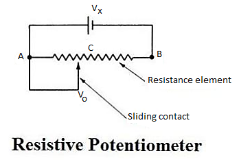
Fig 5 Resistive Potentiometer
Application
- Remote control
- Television
- Motion control
- Transducer
LVDT
Linear displacement is movement in one direction along a single axis. A position or linear displacement sensor is a device whose output signal represents the distance an object has travelled from a reference point. A displacement measurement also indicates the direction of motion.

Fig 6 LVDT
Linear variable differential transformers (LVDT) are used to measure displacement. LVDTs operate on the principle of a transformer. As shown in Figure 2, an LVDT consists of a coil assembly and a core. The coil assembly is typically mounted to a stationary form, while the core is secured to the object whose position is being measured. The coil assembly consists of three coils of wire wound on the hollow form. A core of permeable material can slide freely through the center of the form. The inner coil is the primary, which is excited by an AC source as shown. Magnetic flux produced by the primary is coupled to the two secondary coils, inducing an AC voltage in each coil
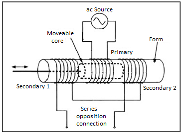
LVTD
Advantages
- High degree of robustness
- No wear in the sensing element
- LVDT can have infinite resolution
Proximity Sensors
Capacitive Sensors
A capacitive proximity sensor senses the presence of an object (usually called the target) without physical contact. They are designed to detect both metallic and non-metallic targets.
Principle
The capacitiveproximity sensor consists a high-frequency oscillator along with a sensing surface formed by two metal electrodes. When an object comes near the sensing surface, it enters the electrostatic field of the electrodes and changes the capacitance of the oscillator.
As a result, the oscillator circuit starts oscillating and changes the output state of the sensor when it reaches certain amplitude. As the object moves away from the sensor, the oscillator’s amplitude decreases, switching the sensor back to its initial state.
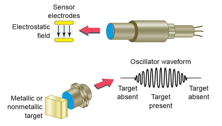
Fig 7 Capacitive type sensors
Application
- Detect cartons of milk
- Used in packing industry
Inductive type Sensor
Inductive proximity sensors are used to detect both ferrous and nonferrous metals (such as copper, aluminium, and brass).Iinductive proximity sensor operates on the eddy current principle.
When a metal object moves into the electromagnetic field of the sensing head, eddy currents are induced in the object. This causes a change in the loading of the oscillator, which then operates the output device.
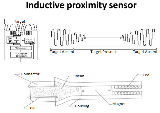
Fig 8 Inductive Proximity Sensor
The operation of an inductive proximity sensor can be summarized as under:
- The oscillator circuit generates a high-frequency electromagnetic field that radiates from the tip of the sensor.
- When a metal target enters the field, eddy currents are induced in the target.
- The eddy currents in the target absorb some of radiated energy from the sensor, which results in a loss of energy and change in field strength of the oscillator.
- The sensor’s detection circuit monitors the oscillator’s strength and triggers a solid-state output device at a specific level.
- Once the metal object leaves the sensing area, the oscillator returns to its initial value.
Application
- To detect bottle caps
- To detect aluminium component
Temperature sensors
RTD (Resistance temperature detector)
An RTD sensor measures temperature based on the resistance changes in a metal resistor inside. The most popular RTDs, called PT100 sensors, use platinum and have a resistance of 100 ohms at 0°C.
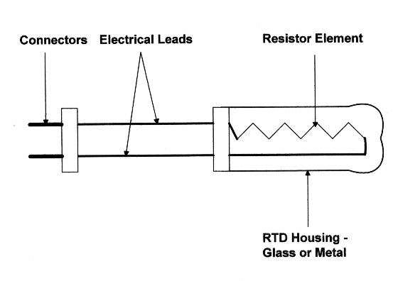
Fig 9 RTD
The electrical resistance of metals rises as heat increases and the metals become hotter, while their electrical resistance falls as heat decreases and the metals become colder. RTDs are temperature sensors that use the changes in the electrical resistance of metals to measure the changes in the local temperature. For the readings to be interpretable, the metals used in RTDs must have electrical resistances known to people and recorded for convenient reference. As a result, copper, nickel, and platinum are all popular metals used in the construction of RTDs.
Thermocouple
Thermocouples are temperature sensors that use two different metals in the sensor to produce a voltage that can be read to determine the local temperature. Different combinations of metals can be used in building the thermocouples to provide different calibrations with different temperature ranges and sensor characteristics.
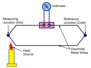
Fig 10 Thermocouple
Advantages and Disadvantages
Sensor type | Advantages | Disadvantages |
Thermocouple | Temperature Range | Cold-junction compensation |
RTD | Accuracy | Lead resistance error |
Characteristics
Sensor type | RTD | Thermocouple |
Temperature Range (typical) | -200 to 650°C | 200 to 1750°C |
Accuracy (typical) | 0.1 to 1°C |
|
Long-term stability @ 100°C | 0.05°C/year | Variable |
Linearity | Fairly linear | Non-linear |
Power required | Constant voltage or current | Self-powered |
Response time | Generally slow | Fast |
Susceptibility to electrical noise | Rarely susceptible | Susceptible / Cold junction compensation |
Cost | High | Low |
Force and Pressure Sensor
Strain Gauge
A strain gauge is an elastically deformable transducer that transforms an applied force or a mechanical displacement into a change in resistance. It is the underlying mechanism for the working of Strain Guage
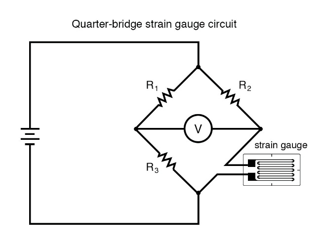
Fig 11 Strain Gauge
Its working principle
We can better understand the working principle of a strain gauge by studying how a strain gauge load cell work. It is the underlying mechanism for the operations of a strain gauge load cell.
This transducer senses an applied load (force weight) and then changes it into an electrical signal output that is proportional to the load. When a load is placed on the load application point of the load cell, it causes a deformation in the dimensions of the underlying strain gauge; this deformation creates changes in its electrical resistance, hence changes in the output electrical voltage. The voltage is then conditioned to give the proportional value of the load applied.
We know, resistance is directly dependent on the length and the cross-sectional area of the conductor given by:
R= L/A
Where,
R = Resistance
L = Length
A = Cross-Sectional Area
The change in the shape and size of the conductor also alters its length and the cross-sectional area which eventually affects its resistance.
Application
- In Aerospace Applications
- Monitoring Bridge Cables with Strain Gauges
- Torque and Power Measurements in Rotating Equipment
Flow Sensor
Electromagnetic
Electromagnetic Flow Meters, simply known as mag flow meter is a volumetric flow meter which is ideally used for waste water applications and other applications that experience low pressure drop and with appropriate liquid conductivity required.
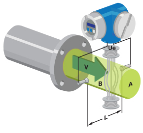
Fig 12 Electromagnetic transducer
Magnetic flow meters’ works based on Faraday’s Law of Electromagnetic Induction. According to this principle, when a conductive medium passes through a magnetic field B, a voltage E is generated which is proportional to the velocity v of the medium, the density of the magnetic field and the length of the conductor.In a magnetic flow meter, a current is applied to wire coils mounted within or outside the meter body to generate a magnetic field. The liquid flowing through the pipe acts as the conductor and this induces a voltage which is proportional to the average flow velocity. This voltage is detected by sensing electrodes mounted in the Magflow meter body and sent to a transmitter which calculates the volumetric flow rate based on the pipe dimensions.
Formula -
v = e/Bl
Q = πd2e/4Bl
Q = Ke
Where
B = Magnetic flux density (Wb/m2)
l = length of conductor (m)
v = Velocity of the conductor (m/s)
d = diameter of the pipe
v = average velocity of flow (conductor velocity in this case)
Key takeaway
The operation of an inductive proximity sensor can be summarized as under:
- The oscillator circuit generates a high-frequency electromagnetic field that radiates from the tip of the sensor.
- When a metal target enters the field, eddy currents are induced in the target.
- The eddy currents in the target absorb some of radiated energy from the sensor, which results in a loss of energy and change in field strength of the oscillator.
- The sensor’s detection circuit monitors the oscillator’s strength and triggers a solid-state output device at a specific level.
- Once the metal object leaves the sensing area, the oscillator returns to its initial value.
Encoder (Absolute & incremental)
The electromechanical device which is setup on the motor shaft and uses digital pulses to track the motor position. The distance from the last position can be determined by counting the number of pulses which the encoder produces. This position helps to track whether the motor is near the target or not. The encoder comprises of a light emitter, a disc which has cut slits around the rim and a light receiver.
As the encoder disc rotates with the motor shaft, the slits on the encoder disc turns the static light source on one side into flashes of light on the other side. The light receiver on the other side detects these light pulses and digitally outputs a square wave pulse signal to the host controller. A pulse is generated each step of the way if the resolution is the same between the encoder and the motor.
The feedback device is an incremental type encoder. It has 2 or 3 channel outputs. Each channel equates to a physical track of cut slits on the outer rim of the encoder disc (200 slits per A/B channel for a typical encoder). The slits for channels A and B are offset or out of phase by 90° in order to tell direction of movement. The 3rd Z channel is just one slit on a single track and can either mark a home position or count the number of revolutions.
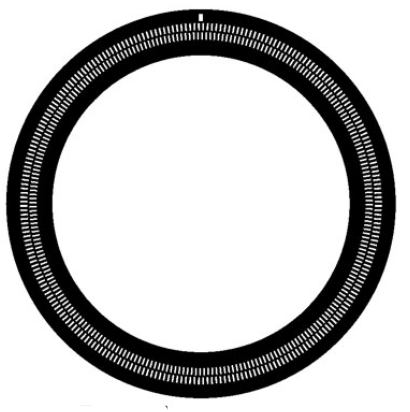
Fig 13 Incremental Encoder
In absolute encoder additional battery is provided in order to keep power on so that the position information for next cycle is not lost. When it is on supply the battery keeps charging and energises motor, driver and encoder. This helps to keep the track of last position. During power cut off the driver and encoder will use battery power to keep the system running.

Fig 14 Absolute Encoder
The design of absolute encoder is similar to incremental except that its circuitry is bit complex.
Lidar
It is Light Detection and Ranging device used for remote sensing to map structures including vegetation height, density and other characteristics across a region. The height and density of vegetation can also be measured with this device. The LiDAR comprises of laser which emits light. The transmitted light reaches the ground and travels back. The reflection which is received tells about the object from which it was reflected. The reflected light energy then returns to the LiDAR sensor where it is recorded.
The time taken for the emitted light to travel to ground and back is measured. This time suggests about the distance travelled. Elevation is than calculated from the distance travelled. The GPS and IMU (internal measurement unit) are main components of LiDAR system which provide orientation of plane in the sky.
Eddy Current
For measuring the displacement and position of electrically conductive targets the eddy current sensors are used. The principle of operation of the sensor is based on the inductive eddy current principle. The distance is measured from the energy which is extracted from the oscillating circuit. This generates eddy current in an electrically conductive material. When alternating current is supplied to the sensing coil a magnetic field is developed around the coil. According to Faraday’s Law when any electrically conductive material is placed in this field eddy current is induced. There is change in impedance of coil when the object moves and this is proportional to the change in the distance between the sensor and the target.
They have temperature stability and are resistant towards dirt, pressure and oil. They can operate at high pressure. They can measure high speed upto 100 kilo samples/second.
Key takeaway
S. No. | Absolute Encoder | Incremental Encoder |
1 | It has unique code for each shaft position which represents the absolute position of the encoder | It generates an output signal each time the shaft rotates at a certain angle. |
2 | Power in needed when readings are noted | It needs power throughout the operation of the device. |
3 | It does not loose the position information when the power is lost | Each time the power is lost the reading must be reinitialized or the system shows an error. |
Proximity Sensors
Capacitive Sensors
A capacitive proximity sensor senses the presence of an object (usually called the target) without physical contact. They are designed to detect both metallic and non-metallic targets.
Principle
The capacitiveproximity sensor consists a high-frequency oscillator along with a sensing surface formed by two metal electrodes. When an object comes near the sensing surface, it enters the electrostatic field of the electrodes and changes the capacitance of the oscillator.
As a result, the oscillator circuit starts oscillating and changes the output state of the sensor when it reaches certain amplitude. As the object moves away from the sensor, the oscillator’s amplitude decreases, switching the sensor back to its initial state.

Fig 15 Capacitive type sensors
Application
- Detect cartons of milk
- Used in packing industry
Inductive type Sensor
Inductive proximity sensors are used to detect both ferrous and nonferrous metals (such as copper, aluminium, and brass).Iinductive proximity sensor operates on the eddy current principle.
When a metal object moves into the electromagnetic field of the sensing head, eddy currents are induced in the object. This causes a change in the loading of the oscillator, which then operates the output device.

Fig 16 Inductive proximity sensor
The operation of an inductive proximity sensor can be summarized as under:
- The oscillator circuit generates a high-frequency electromagnetic field that radiates from the tip of the sensor.
- When a metal target enters the field, eddy currents are induced in the target.
- The eddy currents in the target absorb some of radiated energy from the sensor, which results in a loss of energy and change in field strength of the oscillator.
- The sensor’s detection circuit monitors the oscillator’s strength and triggers a solid-state output device at a specific level.
- Once the metal object leaves the sensing area, the oscillator returns to its initial value.
Optical proximity sensor
A complete optical proximity sensor includes a light source, and a sensor that detects the light. These sensors detect objects directly in front of them by the detecting the sensor’s own transmitted light reflected back from an object’s surface.
Key takeaway
- To detect bottle caps
- To detect aluminium component
Microelectromechanical systems (MEMS) are mechanical devices that are built onto semiconductor chips, generally ranging in size from about 20 micrometres to a millimetre and made up of components 0.001 to 0.1 mm in size. They usually consist of a microprocessor and components such as microsensors and microactuators. MEMS can sense, control and activate mechanical processes on the micro scale. Such MEMS chips are becoming increasingly widely used, and the following is an illustration. Airbags in automobiles are designed to inflate in the event of a crash and so cushion the impact effects on the vehicle occupant. The airbag sensor is a MEMS accelerometer with an integrated micromechanical element which moves in response to rapid deceleration.
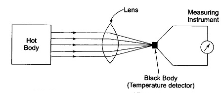
Fig 17 Airbag control system
The rapid deceleration causes a change in capacitance in the MEMS accelerometer, which is detected by the electronics on the MEMS chip and actuates the airbag control unit to fire the airbag. The airbag control unit then triggers the ignition of a gas generator propellant to rapidly inflate a nylon fabric bag. As the vehicle occupant’s body collides with and squeezes the inflated bag, the gas escapes in a controlled manner through small vent holes and so cushions the impact. From the onset of the crash, the entire deployment and inflation process of the airbag is about 60 to 80 milliseconds.
Pyrometer/Infrared Thermometer
This device is used to measure the temperature of any object. It is dependent on the radiation from any object. It has a property of absorbing energy and also measuring of EM wave intensity at any wavelength. The pyrometer is also known as infrared thermometer. They are capable of measuring temperature very accurately and quickly. They are used to measure high-temperature furnaces.

Fig 18 Pyrometer
By sensing heat or radiations emitted from any object they measure temperature. Without any direct contact with the object, they are capable to sense the temperature. Depending upon the intensity pyrometer records the temperature level. The basic components of pyrometer are optical system and detectors. These components are used to measure the surface temperature of the object.
The optical system captures energy emitted from the object whose surface temperature is to be measured with pyrometer. Detector sense the wave of radiation. The temperature level of the object due to radiation is reflected by the detector. The radiation emitted from every targeted object with its actual temperature goes beyond the absolute temperature ( -273.15 degrees Centigrade). This emitted radiation is referred to as Infrared, which is above the visible red light in the electromagnetic spectrum. The radiated energy is used for detecting the temperature of the object and it is converted into electrical signals with the help of a detector.
Infrared Pyrometer
TO detect the thermal radiation from infrared region these pyrometers are used. From the emitted radiation of the targeted object, it measures the temperature. As the thermocouple generate higher current equal to heat emitted is connected further which converts this radiation to electric signal. Infrared pyrometers are made up of pyroelectric materials like polyvinylidene fluoride (PVDF), triglycine sulphate (TGS), and lithium tantalate (LiTaO3).
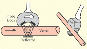
Fig 19 Infrared Pyrometer
Advantages:
- They are capable to measure the temperature of any object without making any contact with the object. This is called Non-contact measurement.
- They are very precise and accurate at the same time.
- While measuring temperature they are very stable.
- It can measure different types of object’s temperature at variable distances.
Force / Pressure Sensors – Strain gauges
Strain Gauge
A strain gauge is an elastically deformable transducer that transforms an applied force or a mechanical displacement into a change in resistance. It is the underlying mechanism for the working of Strain Guage
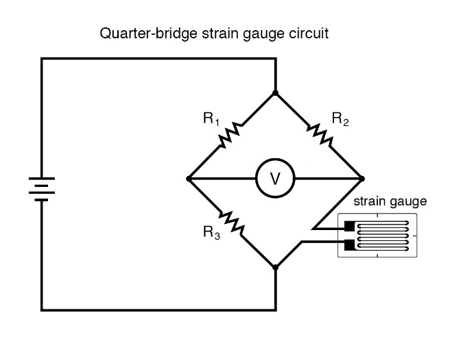
Fig 20 Strain Gauge
Its working principle
We can better understand the working principle of a strain gauge by studying how a strain gauge load cell work. It is the underlying mechanism for the operations of a strain gauge load cell.
This transducer senses an applied load (force weight) and then changes it into an electrical signal output that is proportional to the load. When a load is placed on the load application point of the load cell, it causes a deformation in the dimensions of the underlying strain gauge; this deformation creates changes in its electrical resistance, hence changes in the output electrical voltage. The voltage is then conditioned to give the proportional value of the load applied.
We know, resistance is directly dependent on the length and the cross-sectional area of the conductor given by:
R= L/A
Where,
R = Resistance
L = Length
A = Cross-Sectional Area
The change in the shape and size of the conductor also alters its length and the cross-sectional area which eventually affects its resistance.
Key takeaway
- In Aerospace Applications
- Monitoring Bridge Cables with Strain Gauges
- Torque and Power Measurements in Rotating Equipment
Electromagnetic
Electromagnetic Flow Meters, simply known as mag flow meter is a volumetric flow meter which is ideally used for waste water applications and other applications that experience low pressure drop and with appropriate liquid conductivity required.
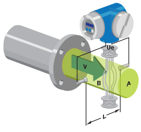
Fig 21 Electromagnetic transducer
Magnetic flow meters’ works based on Faraday’s Law of Electromagnetic Induction. According to this principle, when a conductive medium passes through a magnetic field B, a voltage E is generated which is proportional to the velocity v of the medium, the density of the magnetic field and the length of the conductor.In a magnetic flow meter, a current is applied to wire coils mounted within or outside the meter body to generate a magnetic field. The liquid flowing through the pipe acts as the conductor and this induces a voltage which is proportional to the average flow velocity. This voltage is detected by sensing electrodes mounted in the Magflow meter body and sent to a transmitter which calculates the volumetric flow rate based on the pipe dimensions.
Formula -
v = e/Bl
Q = πd2e/4Bl
Q = Ke
Where
B = Magnetic flux density (Wb/m2)
l = length of conductor (m)
v = Velocity of the conductor (m/s)
d = diameter of the pipe
v = average velocity of flow (conductor velocity in this case)
Ultrasonic
This device measure liquid velocity with ultrasound in order to find the volume of liquid flow. It is a volumetric flow meter and always requires bubble or minute particles within the liquid flow. Mostly we see its application in waste water. Up and down stream transducers, sensor pipe and reflector are used. The velocity of liquid in the pipe is found through the sound waves. There are two conditions in the pipe like no flow and flowing. In the first condition, the frequencies of ultrasonic waves are transmitted into a pipe & its indications from the fluid are similar. In the second condition, the reflected wave’s frequency is dissimilar because of the Doppler Effect.
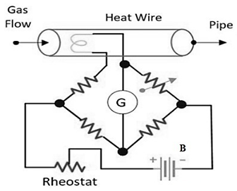
Fig 22 Ultrasonic flowmeter
The frequency shift increases linearly whenever liquid flows through the pipe. The signal from wave is processed by transmitter. The reflection of signal determines the flow rate. Transit time meters transmit & receive ultrasonic waves in both the directions within the pipe.
The time between upstream and downstream in the transducer is same when there is no flow of liquid. When there is flow of liquid the speed at upstream is less than the downstream wave. As the liquid flows faster, the distinction between the up & downstream times raises. The times of the upstream & downstream processed by the transmitter to decide the flow rate.
Hot-wire anemometer
The hot wire anemometer basically measures the direction and velocity of the fluid. The hot wire anemometer is used to measure temperature fluctuations and eddy diameters. This is done by measuring the loss of heat within the wire that is situated in the fluid stream. The thin wire present in the device is heated first to a temperature higher than the ambient temperature. As the temperature of any metal depends upon its resistance, the relation between them is formed as the wire gets cooled as air passes through it.
The wheat stone bridge and conducting wire form the circuit for hot wire anemometer. It works in two ways as discussed below.
Constant Current Method
It is carried out within the flow of liquid. Thus, speed of flow of liquid can be measured. This supplies constant current from the wires and wheat stone bridge is balanced.
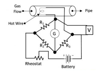
Fig 23 Constant current Anemometer
When it is placed in flow of liquid the heat is transferred to the liquid from wire and it relates to the resistance of the wire. When heat reduces the resistance of wire can be reduced. The change in resistance is measured by the wheat stone bridge which is equal to the speed of the liquid flow.
Constant Temperature Method
The wire gets heated when electric current passes through it. Wherever the speed of fluid low can be measured it is placed. The temperature value of the wire can also modify and its operation can also be done on the principle where the level of temperature of the wire persists to be stable. The entire current that is necessary to bring the wire into the starting state is comparable to the flow of gas speed.
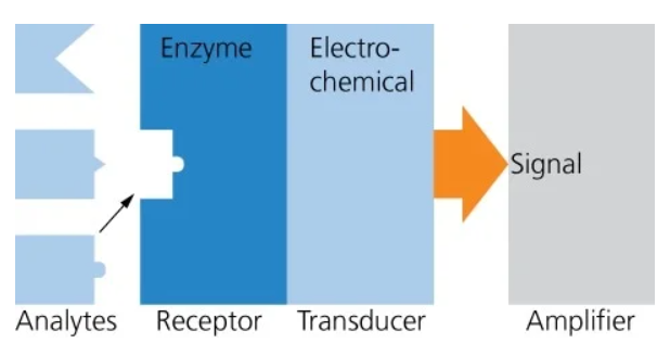
Fig 24 Constant Temperature Anemometer
Key takeaway
This device measure liquid velocity with ultrasound in order to find the volume of liquid flow. It is a volumetric flow meter and always requires bubble or minute particles within the liquid flow. Mostly we see its application in waste water. Up and down stream transducers, sensor pipe and reflector are used.
The Red, green and blue are considered as primary colours. The combination of these colours forms many other colours called as secondary colours. This device is use for detecting colour of materials. The material whose colour is to be detected is illuminated by a light source and the receiver measures the reflected wavelengths. Colour sensors contain a white light emitter to illuminate the surface. Three filters with wavelength sensitivities at 580nm, 540nm, 450nm to measure the wavelengths of red, green and blue colours respectively.
The activation of these filters decides the colour of the material. By illuminating the material surface with red, blue and green LED one at a time colour can be detected. Voltage converters are used here. The colour is detected by the highest amount of light reflected back by the red, blue and green light.
Enzyme
This type of biosensors is used to detect a particular substance (analyte) with high specificity such as glucose, lactate, glutamate and glutamine. The concentration of analyte in an aqueous solution can be measured using this biosensor. The sensor produces an electrical signal which is proportional to the concentration of analyte. An enzymatic biosensor comprises of an enzyme, which recognizes and then reacts with the target analyte producing a chemical signal, a transducer, which produces a physical signal out of that chemical one, and an electronic amplifier, which conditions and then amplifies the signal.
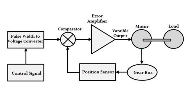
Fig 25 Structure of Biosensor
The metabolism of living organism depends upon the analytes such as lactate, glucose, glutamine and glutamate. The functioning of cells and their growth is supported by glutamine and glucose. Lactate is developed by cells and allows judging the efficiency of the cell metabolism; and glutamate is an amino acid consumed by cells. Each of these analytes needs a particular set of enzymes for its detection.
Constant monitoring on such analytes helps to keep track of health of the patients. This helps to treat and cure the patients on time resulting in lesser fatalities.
ECG
The electrocardiogram (ECG) is used to monitor the proper functioning of heart. The electric signals from the muscle fibres are changed due to stimulation of muscle alters. Cardiac cells, unlike other cells, have a property known as automaticity, which is the capacity to spontaneously initiate impulses. These are then transmitted from cell to cell by gap junctions that connect cardiac cells to each other. The electrical impulses spread through the muscle cells because of changes in ions between intracellular and extracellular fluid. This is referred to as action potential. The primary ions involved are potassium, sodium and calcium. The action potential is the potential for action created by the balance between electrical charges (positive and negative) of ions on either side of the cell membrane. When the cells are in a resting state, the insides are negatively charged compared to the outsides.
Membrane pumps act to maintain this electrical polarity (negative charge) of the cardiac cells. Contraction of the heart muscle is triggered by depolarisation, which causes the internal negative charge to be lost transiently. These waves of depolarisation and repolarisation represent an electrical current and can be detected by placing electrodes on the surface of the body. After the current has spread from the heart through the body, the changes are picked up by the ECG machine and the activity is recorded on previously sensitised paper. The ECG is therefore a graphic representation of the electrical activity in the heart. The current is transmitted across the ECG machine at the selected points of contact of the electrode with the body.
EMG
It is called as Electromyography which measures the electrical activity in response to nerve’s stimulation of muscle. This detects the neuromuscular abnormalities. Few needles are inserted into the body which are basically the electrodes. The electrodes when sense any electrical activity and display it on oscilloscope. The activity can be heard using audio amplifier. EMG measures the electrical activity of muscle during rest, slight contraction and forceful contraction. Muscle tissue does not normally produce electrical signals during rest. When an electrode is inserted, a brief period of activity can be seen on the oscilloscope, but after that, no signal should be present.
Servo motor
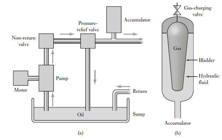
Fig 26 Servo motor
The servo motor is actually an assembly of four things: a normal DC motor, a gear reduction unit, a position-sensing device and a control circuit. The DC motor is connected with a gear mechanism which provides feedback to a position sensor which is mostly a potentiometer. From the gear box, the output of the motor is delivered via servo spline to the servo arm. For standard servo motors, the gear is normally made up of plastic whereas for high power servos, the gear is made up of metal.
The function of the servo motor is to receive a control signal that represents a desired output position of the servo shaft and apply power to its DC motor until its shaft turns to that position.
It uses the position sensing device to figure out the rotational position of the shaft, so it knows which way the motor must turn to move the shaft to the instructed position. The shaft commonly does not rotate freely around similar to a DC motor, however rather can just turn 200 degrees.
Working
The Servo Motor basically consists of a DC Motor, a Gear system, a position sensor and a control circuit. The DC motors get powered from a battery and run at high speed and low torque. The Gear and shaft assembly connected to the DC motors lower this speed into sufficient speed and higher torque. The position sensor senses the position of the shaft from its definite position and feeds the information to the control circuit. The control circuit accordingly decodes the signals from the position sensor and compares the actual position of the motors with the desired position and accordingly controls the direction of rotation of the DC motor to get the required position. The Servo Motor generally requires DC supply of 4.8V to 6 V.
Key takeaway
- They are also used in radio controlled airplanes to control the positioning and movement of elevators.
- They are used in robots because of their smooth switching on and off and accurate positioning.
- They are also used by aerospace industry to maintain hydraulic fluid in their hydraulic systems.
- They are used in many radio controlled toys.
Hydraulic
With a hydraulic system, pressurised oil is provided by a pump driven by an electric motor. The pump pumps oil from a sump through a non-return valve and an accumulator to the system, from which it returns to the sump. Figure illustrates the arrangement. A pressure-relief valve is included, this being to release the pressure if it rises above a safe level, the non-return valve is to prevent the oil being back driven to the pump and the accumulator is to smooth out any short-term fluctuations in the output oil pressure. Essentially the accumulator is just a container in which the oil is held under pressure against an external force, Figure (b) showing the most commonly used form which is gas pressurised and involves gas within a bladder in the chamber containing the hydraulic fluid; an older type involved a spring-loaded piston. If the oil pressure rises then the bladder contracts, increases the volume the oil can occupy and so reduces the pressure. If the oil pressure falls, the bladder expands to reduce the volume occupied by the oil and so increases its pressure.
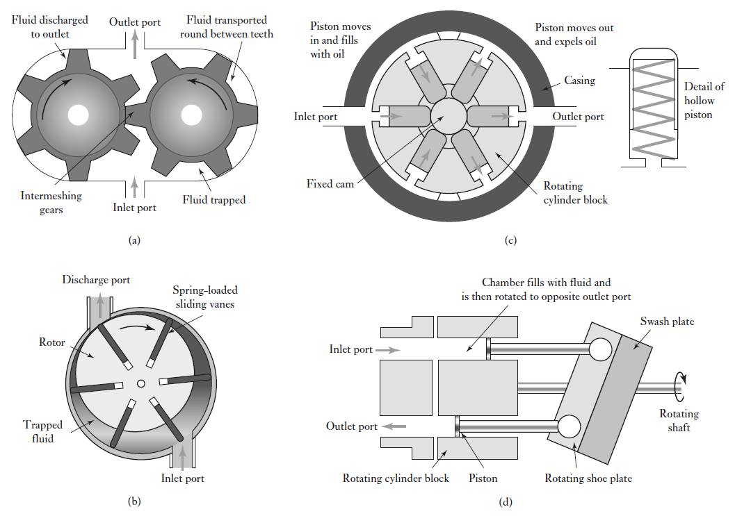
Fig 27 Hydraulic power supply(a) Accumulator (b)
Commonly used hydraulic pumps are the gear pump, the vane pump and the piston pump. The gear pump consists of two close-meshing gear wheels which rotate in opposite directions. Fluid is forced through the pump as it becomes trapped between the rotating gear teeth and the housing and so is transferred from the inlet port to be discharged at the outlet port. Such pumps are widely used, being low cost and robust. They generally operate at pressures below about 15 MPa and at 2400 rotations per minute. The maximum flow capacity is about 0.5 m3/min. However, leakage occurs between the teeth and the casing and between the interlocking teeth, and this limits the efficiency. The vane pump has spring-loaded sliding vanes slotted in a driven rotor (Figure (b)).
As the rotor rotates, the vanes follow the contours of the casing. This results in fluid becoming trapped between successive vanes and the casing and transported round from the inlet port to outlet port. The leakage is less than with the gear pump. Piston pumps used in hydraulics can take a number of forms. With the radial piston pump (Figure (c)), a cylinder block rotates round the stationary cam and this causes hollow pistons, with spring return, to move in and out. The result is that fluid is drawn in from the inlet port and transported round for ejection from the discharge port.
The axial piston pump (Figure (d)) has pistons which move axially rather than radially. This plate is at an angle to the drive shaft and thus as the shaft rotates, they move the pistons so that air is sucked in when a piston is opposite the inlet port and expelled when it is opposite the discharge port. Piston pumps have a high efficiency and can be used at higher hydraulic pressures than gear or vane pumps.
Fig 28 Gear pump(a), vane pump(2), radial piston pump (3), axial piston pump(4)
Pneumatic
With a pneumatic power supply an electric motor drives an air compressor. The air inlet to the compressor is likely to be filtered and via a silencer to reduce the noise level. A pressure-relief valve provides protection against the pressure in the system rising above a safe level. Since the air compressor increases the temperature of the air, there is likely to be a cooling system and to remove contamination and water from the air a filter with a water trap.
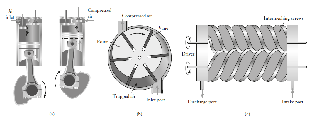
Fig 29 Pneumatic Power Supply
An air receiver increases the volume of air in the system and smoothed out any short-term pressure fluctuations. Commonly used air compressors are ones in which successive volumes of air are isolated and then compressed. Figure shows the basic form of compressor we might have the first stage taking air at atmospheric pressure and compressing it to, say, 2 bar and then the second stage compressing this air to, say, 7 bar. Reciprocating piston compressors can be used as a single-stage compressor to produce air pressures up to about 12 bar and as a multistage compressor up to about 140 bar.
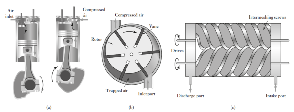
Fig 30 (a) Single-acting, single stage, vertical, reciprocating compressor, (b) rotary vane compressor, (c) screw compressor.
Typically, air flow deliveries tend to range from about 0.02 m3_min free air delivery to about 600 m3_min free air delivery; free air is the term used for air at normal atmospheric pressure. Another form of compressor is the rotary vane compressor. This has a rotor mounted eccentrically in a cylindrical chamber (Figure(b)). The rotor has blades, the vanes, which are free to slide in radial slots with rotation causing the vanes to be driven outwards against the walls of the cylinder. As the rotor rotates, air is trapped in pockets formed by the vanes and as the rotor rotates so the pockets become smaller and the air is compressed. Compressed packets of air are thus discharged from the discharge port. Single-stage, rotary vane compressors typically can be used for pressures up to about 800 kPa with flow rates of the order of 0.3 m3/min to 30 m3/min free air delivery. Another form of compressor is the rotary screw compressor (Figure(c)).
This has two intermeshing rotary screws which rotate in opposite directions. As the screws rotate, air is drawn into the casing through the inlet port and into the space between the screws. Then this trapped air is moved along the length of the screws and compressed as the space becomes progressively smaller, emerging from the discharge port. Typically, single-stage, rotary screw compressors can be used for pressures up to about 1000 kPa with flow rates of between 1.4 m3/min and 60 m3/min free air delivery.
It is one type of gear motor having various voltages and is main torque producing component. The electric actuators are set with thermal overload sensor in order to stop extreme current draw. It is in series with the power source and when motor attains secure operating temperature locks the circuit.
For electric motor when power is supplied to windings magnetic field is generated causing the armature to rotate. The actuators have to rely on gear train as they are attached to the motor, improving motors torque and also the output speed of actuators. The single way to alter the o/p speed is to fit a cycle length control module. This module lets an increase in cycle time only. If a reduction in cycle time is necessary, an alternating actuator with the preferred cycle time and correct output torque must be used.
In selecting a sensor and actuators for a particular application there are a number of factors that need to be considered.
- The nature of the measurement required, e.g. The variable to be measured, its nominal value, the range of values, the accuracy required, the required speed of measurement, the reliability required, the environmental conditions under which the measurement is to be made.
- The nature of the output required from the sensor, this determining the signal conditioning requirements in order to give suitable output signals from the measurement.
- Then possible sensors can be identified, taking into account such factors as their range, accuracy, linearity, speed of response, reliability, maintainability, life, power supply requirements, ruggedness, availability, cost. The selection of sensors cannot be taken in isolation from a consideration of the form of output that is required from the system after signal conditioning, and thus there has to be a suitable marriage between sensor and signal conditioner.
References:
- Alciatore & Histand, Introduction to Mechatronics and Measurement system, 4th Edition, Mc-Graw Hill publication, 2011
- Bishop (Editor), Mechatronics – An Introduction, CRC Press, 2006
- Mahalik, Mechatronics – Principles, concepts and applications, Tata Mc-Graw Hill publication, New Delhi
- C. D. Johnson, Process Control Instrumentation Technology, Prentice Hall, New Delhi