Unit - 6
Programmable Logic Controller (PLC)
A PLC is an industrial-grade digital computer designed to perform control functions—especially for industrial applications.
The majority of PLCs today are modular, allowing the user to add an assortment of functionality including discrete control, analog control, PID control, position control, motor control, serial communication, and high-speed networking. Compared to older technologies, the PLC is easier to troubleshoot, more reliable, more cost-effective, and far more versatile.
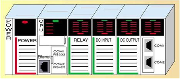
Fig 1 PLC
Advantages
- They are user friendly and easy to operate
- They eliminate the need for hard wired relay logic
- They are fast
- It is suitable for automation in industries.
- Its input and output modules can be extended depending upon the requirements
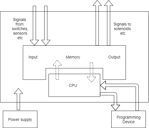
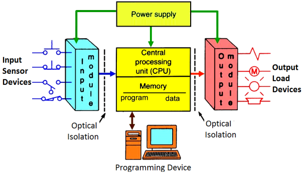
Fig 2 Architecture of PLC
A basic PLC system consists of the following sections:
- Input/ Output Section: The input section or input module consists of devices like sensors, switches and many other real world input sources. The input from the sources is connected to the PLC through the input connector rails. The output section or output module can be a motor or a solenoid or a lamp or a heater, whose functioning is controlled by varying the input signals.
- CPU or Central Processing Unit: It is the brain of the PLC. It can be a hexagonal or an octal microprocessor. It carries out all the processing related to the input signals in order to control the output signals based on the control program.
- Programming Device: It is the platform where the program or the control logic is written. It can be a handheld device or a laptop or a computer itself.
- Power Supply: It generally works on a power supply of about 24 V, used to power input and output devices.
- Memory: The memory is divided into two parts- The data memory and the program memory. The program information or the control logic is stored in the user memory or the program memory from where the CPU fetches the program instructions. The input and output signals and the timer and counter signals are stored in the input and output external image memory respectively
Working of a PLC
- The input sources convert the real time analog electric signals to suitable digital electric signals and these signals are applied to the PLC through the connector rails.
- These input signals are stored in the PLC external image memory in locations known as bits. This is done by the CPU
- The control logic or the program instructions are written onto the programming device through symbols or through mnemonics and stored in the user memory
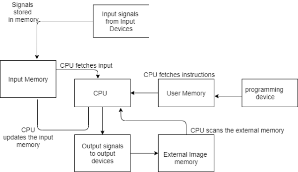
Fig 3 Logic Unit
- The execution results are then stored in the external image memory which controls the output drives.
- The CPU also keeps a check on the output signals and keeps updating the contents of the input image memory according to the changes in the output memory.
- The CPU also performs internal programming functioning like setting and resetting of the timer, checking the user memory.
Key takeaway
PLC has I/O section, CPU, programming device, power supply and memory.
PLC selection criteria consists of
* System (task) requirements.
* Application requirements.
* What input/output capacity is required?
* What type of inputs/outputs are required?
* What size of memory is required?
* What speed is required of the CPU?
* Electrical requirements.
* Speed of operation.
* Communication requirements.
* Software.
* Operator interface.
* Physical environments.
System requirements
* The starting point in determining any solution must be to understand what is to be achieved.
* The program design starts with breaking down the task into a number of simple understandable elements, each of which can be easily
described.
Application requirements
* Input and output device requirements. After determining the operation of the system, the next step is to determine what input and
output devices the system requires.
* List the function required and identify a specific type of device.
* The need for special operations in addition to discrete (On/Off) logic.
* List the advanced functions required beside simple discrete logic.
Electrical Requirements
The electrical requirements for inputs, outputs, and system power; When determining the electrical requirements of a system, consider three items:
- Incoming power (power for the control system);
- Input device voltage; and
- Output voltage and current.
Speed of Operation
How fast the control system must operate (speed of operation).
When determining speed of operation, consider these points:
– How fast does the process occur or machine operate?
– Are there “time critical” operations or events that must be detected?
– In what time frame must the fastest action occur (input device detection to
Output device activation)?
– Does the control system need to count pulses from an encoder or flow-meter and respond quickly?
Communication
If the application requires sharing data outside the process, i.e., communication. Communication involves sharing application data or status with another electronic device, such as a computer or a monitor in an operator’s station. Communication can take place locally through a twisted-pair wire, or remotely via telephone or radio modem.
Operator Interface
If the system needs operator control or interaction. In order to convey information about machine or process status, or to allow an operator to input data, many applications require operator interfaces. Traditional operator interfaces include pushbuttons, pilot lights and LED numeric display. Electronic operator interface devices display messages about machine status in descriptive text, display part count and track alarms. Also, they can be used for data input.
Physical Environment
The physical environment in which the control system will be located. Consider the environment where the control system will be located. In harsh environments, house the control system in an appropriate IP-rated enclosure. Remember to consider accessibility for maintenance, troubleshooting or reprogramming.
Key takeaway
* The starting point in determining any solution must be to understand what is to be achieved.
* The program design starts with breaking down the task into a number of simple understandable elements, each of which can be easily
described.
Different types of ladder logic diagram that perform different logic gate functions. Basically, there are seven types of logic gates as below.
- NOT Gate
- AND Gate
- OR Gate
- NAND Gate
- NOR Gate
- EX-OR Gate
- EX-NOR Gate
1. NOT GATE
In electronics, NOT GATE is also called an Inverter or Buffer.
Working: NOT gate works as inversion. It takes one input and gives one output. When the input is high then the output is low and vice-versa.
Logic Gate Truth Table for NOT Gate:
Input (I1) | Output (Q1) |
0 | 1 |
1 | 0 |
NOT Gate in PLC programming:
In the case of PLC ladder, there will be a push button to provide input. When (I1) is pressed then the coil (Q1) is on. And when Input (I1) is released then coil (Q1 is off.
Symbolic Representation.

Fig 4 NOT gate in PLC
2. AND GATE
Working: In AND Gate, when both inputs (I1 and I2) are high then the output (Q1) will be high. For all other inputs, output (Q1) will be the low.
Logic Gate Truth Table for AND Gate:
Input (I1) | Input (I2) | Output (Q1) |
0 | 0 | 0 |
0 | 1 | 0 |
1 | 0 | 0 |
1 | 1 | 1 |
AND Gate in PLC programming:
Using Ladder diagram programming, we are connecting two switches (I1 and I2) as input and coil/lamp (Q1) as output.
In the case of both switches (I1 and I2) are closed, the lamp (Q1) will glow. In another case, if any of the switches (I1 or I2) are open then lamp (Q1) will not glow.
Symbolic Representation as,

Fig 5 AND gate in PLC
3. OR GATE
Working: If both inputs are low in the OR gate, then the output will be low. For all other cases, the output will be high.
Logic Gate Truth Table for OR Gate:
Input (I1) | Input (I2) | Output (Q1) |
0 | 0 | 0 |
0 | 1 | 1 |
1 | 0 | 1 |
1 | 1 | 1 |
OR Gate in PLC programming:
In case both or anyone inputs (I1 and I2) are closed then coil (Q1) will on.
Symbolic Representation as,
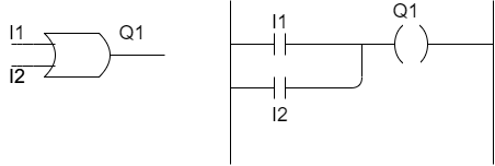
Fig 6 OR gate in PLC
4. NAND GATE
NAND gate is operated as an AND gate and followed by the inverter.
Working: In NAND Gate, the output will be low when both inputs are high. For all other cases, the output will be high.
Logic Gate Truth Table for NAND Gate:
Input (I1) | Input (I2) | Output (Q1) |
0 | 0 | 1 |
0 | 1 | 1 |
1 | 0 | 1 |
1 | 1 | 0 |
NAND Gate in PLC programming:
If both switches (I1 and I2) or anyone switch (I1 or I2) are closed, the lamp will be glow. In the case, both switches are open then the lamp will not be glow.
Symbolic Representation as,
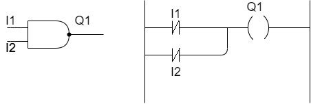
Fig 7 NAND Gate in PLC
5. NOR GATE
NOR Gate is operated OR Gate followed by the NOT Gate.
When both inputs are low then the output will be high. Otherwise, the low output will occur if both inputs are high.
Logic Gate Truth Table for NOR Gate:
Input (I1) | Input (I2) | Output (Q1) |
0 | 0 | 1 |
0 | 1 | 0 |
1 | 0 | 0 |
1 | 1 | 0 |
NOR Gate in PLC programming:
The Coil (Q1) will be activated if both inputs are closed. Coil (Q1) will be deactivated if anyone or both the inputs are open.
Symbolic Representation as,
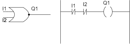
Fig 8 NOR gate in PLC
6. EX-OR GATE
Working: If both inputs are high or low, the output will become low. For any other input condition, the output will be high.
Logic Gate Truth Table for EX-OR Gate:
Input (I1) | Input (I2) | Output (Q1) |
0 | 0 | 0 |
0 | 1 | 1 |
1 | 0 | 1 |
1 | 1 | 0 |
EX-OR Gate in PLC programming:
In the function of EX-OR Gate, the lamp will be on if one switch is closed and another switch is opened.
Symbolic Representation as,

Fig 9 EX-OR Gate in PLC
7. EX-NOR GATE
Working: When both inputs (I1 and I2) are high or low then the output will high. If anyone input is high or low then the output will become low.
Logic Gate Truth Table for EX-NOR Gate:
Input (I1) | Input (I2) | Output (Q1) |
0 | 0 | 1 |
0 | 1 | 0 |
1 | 0 | 0 |
1 | 1 | 1 |
EX_NOR gate in PLC programming:
The function of EX-NOR Gate, the lamp (Q1) will be on if both switches (I1 and I2) are open or closed. The lamp (Q1) will not be on if anyone switches (I1) is activated and another switch (I2) is deactivated.
Symbolic Representation as,

Fig 10 EX-NOR Gate in PLC
Key takeaway
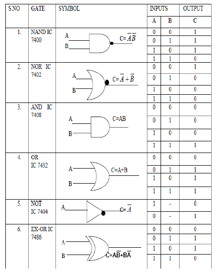
S.No | GATE | SYMBOL | Input | Output | |
A | B | C | |||
1 | NAND IC 7400 |
| 0 | 0 | 1 |
0 | 1 | 1 | |||
1 | 0 | 1 | |||
1 | 1 | 0 | |||
2 | NOR IC 7402 |
| 0 | 0 | 1 |
0 | 1 | 0 | |||
1 | 0 | 0 | |||
1 | 1 | 0 | |||
3 | AND IC 7408 |
| 0 | 0 | 0 |
0 | 1 | 0 | |||
1 | 0 | 0 | |||
1 | 1 | 1 | |||
4 | OR IC 7432 |
| 0 | 1 | 0 |
0 | 1 | 1 | |||
1 | 0 | 1 | |||
1 | 1 | 1 | |||
5 | NOT IC 7404 |
| 0 | 1 | 0 |
1 | 0 | 1 | |||
6 | EX-OR IC 7486 |
| 0 | 0 | 0 |
0 | 1 | 1 | |||
1 | 0 | 1 | |||
1 | 1 | 0 | |||
There are often situations where it is necessary to hold an output energized, even when the input ceases. A simple example of such a situation is a motor, which is started by pressing a push button switch. Though the switch contacts do not remain closed, the motor is required to continue running until a stop push button switch is pressed.
The term latch circuit is used for the circuit used to carry out such an operation. It is a self-maintaining circuit in that, after being energized, it maintains that state until another input is received.
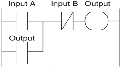
Fig 11 Latching
PLC Latching Function
An example of a latch circuit is shown in Figure. When the input A contacts close, there is an output. However, when there is an output, another set of contacts associated with the output closes.
These contacts form an OR logic gate system with the input contacts. Thus, even if the input A opens, the circuit will still maintain the output energized. The only way to release the output is by operating the normally closed contact B.
Timers
A timer is a specialized type of clock which is used to measure time intervals. A timer that counts from zero upwards for measuring time elapsed is often called a stopwatch. It is a device that counts down from a specified time interval and used to generate a time delay, for example, an hourglass is a timer.
Counters
A counter is a device that stores (and sometimes displays) the number of times a particular event or process occurred, with respect to a clock signal. It is used to count the events happening outside the microcontroller. In electronics, counters can be implemented quite easily using register-type circuits such as a flip-flop.
Difference between a Timer and a Counter
The points that differentiate a timer from a counter are as follows −
Timer | Counter |
The register incremented for every machine cycle. | The register is incremented considering 1 to 0 transition at its corresponding to an external input pin (T0, T1). |
Maximum count rate is 1/12 of the oscillator frequency. | Maximum count rate is 1/24 of the oscillator frequency. |
A timer uses the frequency of the internal clock, and generates delay. | A counter uses an external signal to count pulses. |
A mechanical solution could involve a rotating cam figure below. The cam would be rotated at a constant rate and the cam follower used to actuate a switch, the length of time for which the switch is closed depending on the shape of the cam. This is a solution that has widely been used in the past. A PLC solution could involve the arrangement with the given ladder program.
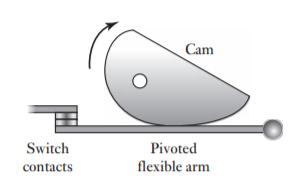
Fig 12 Cam-operated switch
This would have the advantage over the rotating cam of having off and on times which can be adjusted by purely changing the timer preset values in the program, whereas a different cam is needed if the times have to be changed with the mechanical solution. The software solution is much easier to implement than the hardware one. A [1] microprocessor-based solution could involve a microprocessor combined with a memory chip and input/output interfaces. The program is then used to switch an output on and then off after some time delay, with the time delay being produced by a block of program in which there is a timing loop. This generates a time delay by branching round a loop the number of cycles required to generate the requisite time.
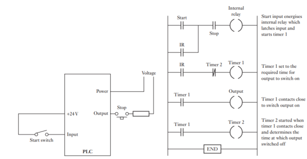
Fig 13 PLC Timer System
Thus, in assembly language we might have:
DELAY LDX #F424; F424 is number of loops
LOOP DEX
BNE LOOP
RTS
Another possibility is to use the timer system in a microcontroller such as MC68HC11. This is based on a 16-bit counter TCNT operating from the system E-clock signal. The system E-clock can be prescaled by setting bits in the timer interrupt mask register 2 (TMSK2) address $1024 The TCNT register starts at $0000 when the processor is reset and counts continuously until it reaches the maximum count of $FFFF. On the next pulse it overflows and reads $0000 again. When it overflows, it sets the timer overflow flag TOF (bit 7 in miscellaneous timer interrupt flag register 2, TFLG2 at address $1025). Thus, with a prescale factor of 1 and an E-clock of 2 MHz, overflow occurs after 32.768 ms. One way of using this for timing is for the TOF flag to be watched by polling. When the flag is set, the program increments its counter. The program then resets the flag, by writing a 1 to bit 7 in the TFLG2 register. Thus, the timing operation just consists of the program waiting for the required number of over flag settings. A better way of timing involves the use of the output-compare function. Port A of the microcontroller can be used for general inputs or outputs or for timing functions.
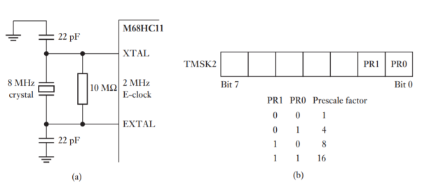
Fig 14(a) Generating 2 MHz internal clock, (b) prescale factor.
The timer has output pins, OC1, OC2, OC3, OC4 and OC5, with internal registers TOC1, TOC2, TOC3, TOC4 and TOC5. We can use the output-compare function to compare the values in the TOC1 to TOC5 registers with the value in the free-running counter TCNT. This counter starts at 0000 when the CPU is reset and then runs continuously. When a match occurs between a register and the counter, then the corresponding OCx flag bit is set and output occurs through the relevant output pin. Thus, by programming the TOCx registers, so the times at which outputs occur can be set. The output-compare function can generate timing delays with much higher accuracy than the timer overflow flag
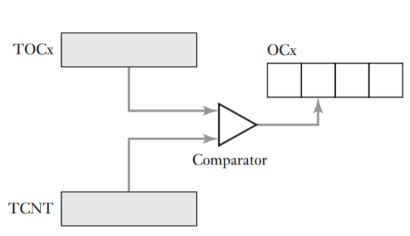
Fig 15 Output compare.
The following program illustrates how output compare can be used to produce a time delay. The longest delay that can be generated in one output-compare operation is 32.7 ms when the E-clock is 2 MHz. In order to generate longer delays, multiple output-compare operations are required. Thus, we might have each output-compare operation producing a delay of 25 ms and repeating this 40 times to give a total delay of 1 s.
REGBAS EQU $1000; Base address of registers
TOC2 EQU $18; Offset of TOC2 from REGBAS
TCNT EQU $0E; Offset of TCNT from REGBAS
TFLG1 EQU $23; Offset of TFLGI from REGBAS
OC1 EQU $40; Mask to clear OC1 pin and OC1F flag
CLEAR EQU $40; Clear OC2F flag
D25MS EQU 50000; Number of E-clock cycles to generate a 25 ms delay
NTIMES EQU 40; Number of output-compare operations needed to give 1 s delay ORG $1000
COUNT RMB 1; Memory location to keep track of the number of; output-compare operations still to be carried out
ORG $C000; Starting address of the program
LDX #REGBAS
LDAA #OC1; Clear OC1 flag
STAA TFLG1, X
LDAA #NTIMES; Initialise the output-compare count
STAA COUNT
LDD TCNT, X
WAIT ADDD #D25MS; Add 25 ms delay
STD TOC2, X; Start the output-compare operation
BRCLR TFLG1, X OC1; Wait until the OC1F flag is set
LDAA #OC1; Clear the OC1F flag
STAA TFLG1, X
DEC COUNT; Decrement the output-compare counter
BEQ OTHER; Branch to OTHER if 1 s elapsed
LDD TOC2, X; Prepare to start the next compare operation
BRA WAIT
OTHER; The other operations of the program which occur after the 1 s delay
Another possible method of producing a timed output signal is to use a timer module, e.g., 555. With the 555 timer, the timing intervals are set by external resistors and capacitors Figure below shows the timer and the external circuitry needed to give an on output when triggered, the duration of the on output being 1.1RC. Large times need large values of R and C. R is limited to about 1 MV, otherwise leakage becomes a problem, and C is limited to about 10 μF if electrolytic capacitors with the problems of leakage and low accuracy are to be avoided. Thus, the circuit shown is limited to times less than about 10 s. The lower limit is about R 5 1 kV and C 5 100pF, i.e., times of a fraction of a millisecond. For longer times, from 16 ms to days, an alternative timer such as the ZN1034E can be used.
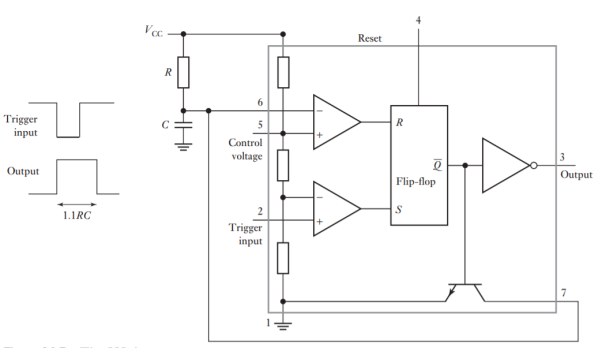
Fig16- 555 Timer
Hydraulic and pneumatic rams are widely used to drive robot arms since they can easily be controlled to move limbs at a relatively slow speed, while electric motors would need to operate through a gearbox
The positions of the arm and gripper in Figure below are determined by limit switches. This means that only two positions can be accurately attained with each actuator and the positions cannot be readily changed without physically moving the positions of the switches. The arrangement is an open-loop control system. In some applications this may not be a problem. However, it is more common to use closed-loop control with the positions of an arm and gripper being monitored by sensors and fed back to be compared in the controller with the positions required. When there is a difference from the required positions, the controller operates actuators to reduce the error. The angular position of a joint is often monitored by using an encoder, this being capable of high precision. Figure below shows a closed-loop arrangement that might be used for linear motion of a robot arm.

Fig 17 Closed-loop control for limb.
The output from the actuator is a force F applied to move the end of the limb. For a set position of ys and an actual position y, the error signal will be ys- y, assuming for simplicity that the measurement system has a gain of 1. If we consider the controller to have a gain of Gc and Ga to be that of the actuator assembly, then F =GcGa (ys -y). The masses to be accelerated by this force are the mass of the load that the arm is carrying, the mass of the arm and the mass of the moving parts of the actuator. If this is a total mass of m, then Newton’s law gives F = ma, where the acceleration a can be written as d2y/dt2. However, this does not take account of friction and since we can take the friction force to be proportional to the velocity, the frictional force is k dy/dt. Thus, we can write


This is a second-order differential equation and so the deflection y and the form it will take will depend on the damping factor. An under-damped system will have a natural angular frequency ωn given by

This angular frequency will determine how fast the system responds to a change the larger the angular frequency, the faster the system responds (the rise time is inversely proportional to the angular frequency). This means that increasing the controller gain or decreasing the mass can increase the speed of response. The damping factor  is given from the differential equation as

Key takeaway
The time taken for the oscillations to die away, i.e., the settling time, is inversely proportional to the damping factor and so, for example, increasing any part of the mass will result in a decrease in the damping factor and so the oscillations take longer to die away.
References:
- Alciatore & Histand, Introduction to Mechatronics and Measurement system, 4th Edition, Mc-Graw Hill publication, 2011
- Bishop (Editor), Mechatronics – An Introduction, CRC Press, 2006
- Mahalik, Mechatronics – Principles, concepts and applications, Tata Mc-Graw Hill publication, New Delhi
- C. D. Johnson, Process Control Instrumentation Technology, Prentice Hall, New Delhi