Back to Study material
Metrology And Quality Control

Unit - 2

Comparators, Thread and Gear Metrology, Surface Roughness

Measurement

  • Mechanical comparators provide simple and cost-effective solutions. The skills for fabricating and using them is quite easy compared to other types of comparators.
  • In mechanical comparators magnification of plunger movement can be obtained by using levers, gear and pinion arrangement or other mechanical means.
  • The following are some of the important comparators in metrology.
  •  

  • Dial Indicator
  • The dial indicator or the dial gauge is one of the simplest and the most widely used comparator.
  • It is primarily used to compare workpieces against a master.
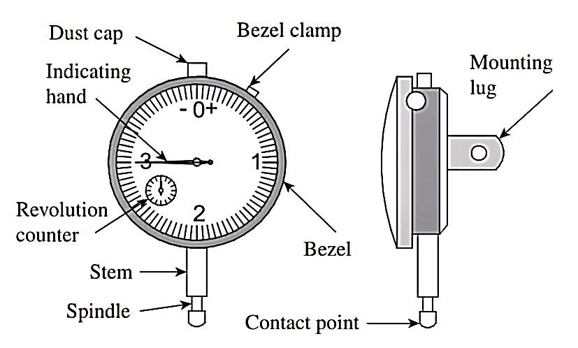
  • The basic features of a dial gauge consist of a body with a circular graduated dial, a contact point connected to a gear train, and an indicating hand that directly indicates the linear displacement of the contact point.
  • The contact point is first set against the master, and the dial scale is set to zero by rotating the bezel.
  • Now, the master is removed and the workpiece is set below the contact point; the difference in dimensions between the master and the workpiece can be directly read on the dial scale.
  • Dial gauges are used along with V-blocks in a metrology laboratory to check the roundness of components. A dial gauge is also part of standard measuring devices such as bore gauges, depth gauges, and vibrometers.
  • The contact point in a dial indicator is of an interchangeable type and provides versatility to the instrument. It is available as a mounting and in a variety of hard, wear-resistant materials.
  • The bezel clamp enables locking of the dial after setting the scale to zero.
  • The scale of the dial indicator, usually referred to as dial, provides the required least count for measurement, which normally varies from 0.01 to 0.05 mm. The scale has a limited range of linear measurements, varying from 5 to 25 mm.
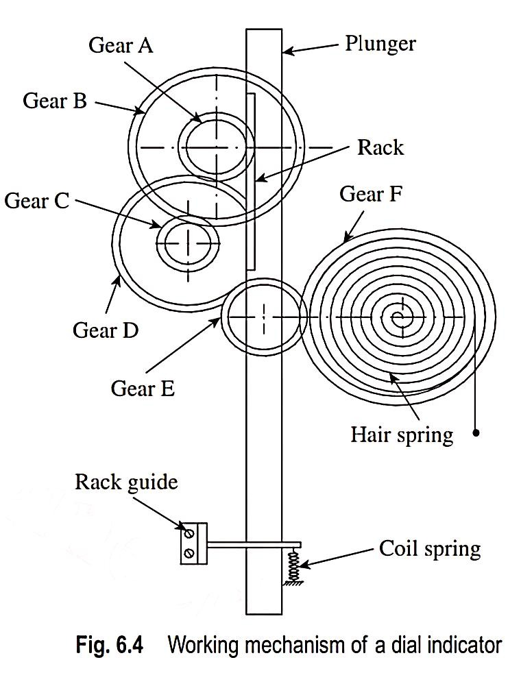
  • Figure illustrates the mechanism used in a dial indicator in order to achieve high magnification using a set of gears and pinions.
  • The plunger and spindle are usually one piece.
  • The spindle attached to the bottom of the rack is the basic sensing element.
  • A coil spring resists the measurement movement and thereby applies the necessary gauging pressure.
  • It also returns the mechanism to the ‘at-rest’ position after each measurement.
  • The plunger carries a rack, which meshes with a gear A.
  • A rack guide prevents the rotation of the plunger about its own axis.
  • A small movement of the plunger causes the rack to turn gear A.
  • A larger gear, B, mounted on the same spindle as gear A, rotates by the same amount and transfers motion to gear C.
  • Attached to gear C is another gear, D, which meshes with gear E.
  • Gear F is mounted on the same spindle as the indicator pointer. Thus, the overall magnification obtained in the gear train A–B–
  • C–D–E is given by TD/TE × TB/TC, where TD, TE, TB, and TC are the number of teeth on the gears D, E, B, and C, respectively.
  • The magnification is further enhanced at the tip of the pointer, depending on the length of the pointer.
  • A hair spring loads all the gears in the train against the direction of gauging movement. This eliminates backlash that would be caused by gear wear.
  • The gears are precision cut and usually mounted on jewelled bearings.
  • The dial indicator can be moved up and down and clamped to the stand at any desired position, thereby enabling the inspection of components of various sizes.
  • The indicator is moved up and the standard is placed on the reference surface, while ensuring that the spindle of the indicator does not make contact with the standard.
  • Next, the stand clamp is loosened and the spindle of the indicator is gently lowered onto the surface of the standard such that the spindle is under the required gauge pressure.
  • Now, the indicator is held in position by tightening the stand clamp.
  • The bezel clamp is loosened, the bezel is rotated, and the reading is set to zero.
  • Once the zero setting is done, the standard is gently taken out by hand and the workpieces are gently inserted below the spindle, one by one.
  • Most of the dial indicators are provided with a plunger lifting lever, which provides a slight upward motion of the spindle and enables inserting and withdrawing of workpieces, without causing damage to the indicator mechanism.
  • Now, the difference in height between the standard and the workpiece is read from the dial gauge scale.
  •  

    2.     Sigma Comparator

  • It is a simple mechanical comparator developed by the Sigma Instrument Company, USA.
  • A linear displacement of a plunger is translated into the movement
  • of a pointer over a calibrated scale.

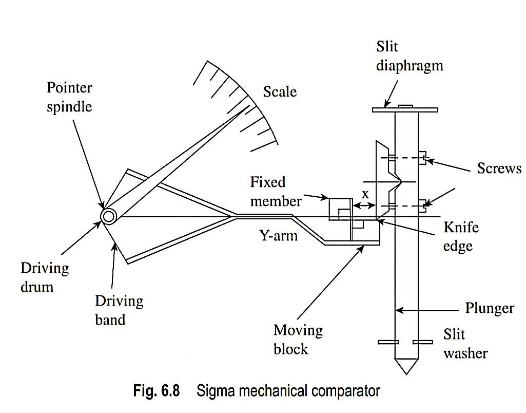
  • Figure illustrates the working parts of a Sigma mechanical comparator.
  • The plunger is the sensing element that is in contact with the work part.
  • It moves on a slit washer, which provides frictionless linear movement and also arrests rotation of the plunger about its axis.
  • A knife edge is screwed onto the plunger, which bears upon the face of the moving member of a cross-strip hinge.
  • This unit comprises a fixed member and a moving block, connected by thin flexible strips at right angles to each other.
  • Whenever the plunger moves up or down, the knife edge drives the moving member of the cross-strip hinge assembly.
  • This deflects an arm, which divides into a ‘Y’ form.
  • The extreme ends of this Y-arm are connected to a driving drum by means of phosphor-bronze strips.
  • The movement of the Y-arm rotates the driving drum and, in turn, the pointer spindle.
  • This causes the movement of the pointer over a calibrated scale.
  • The magnification of the instrument is obtained in two stages. In the first stage, if the effective length of Y-arm is L and the distance from the hinge pivot to the knife edge is x, then magnification is L/x.
  • The second stage of magnification is obtained with respect to the pointer length R and driving drum radius r.
  • The magnification is given by R/r.
  • Therefore, overall magnification is given by (L/x) × (R/r).
  • Thus, the desired magnification can be obtained by adjusting the distance x by operating the two screws that hold the knife edge to the plunger.
  • In addition, the second level of magnification can be adjusted by using driving drums of different radii (r).
  •  

    3.     Johansson Mikrokator

  • The basic element in this type of comparator is a light pointer made of glass fixed to a thin twisted metal strip.
  • This type of comparator, which was developed by the Johansson Ltd Company of USA.
  • The basic principle is referred to as the ‘Abramson movement’
  • after H. Abramson who developed the comparator.
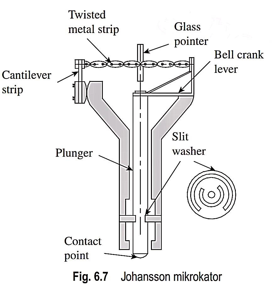
  • The two halves of the thin metal strip, which carries the light pointer, are twisted in opposite directions.
  • Therefore, any pull on the strip will cause the pointer to rotate.
  • While one end of the strip is fixed to an adjustable cantilever link, the other end is anchored to a bell crank lever, as shown in Fig.
  • The other end of the bell crank lever is fixed to a plunger. Any linear motion of the plunger will result in a movement of the bell crank lever, which exerts either a push or a pull force on the metal strip.
  • Accordingly, the glass pointer will rotate either clockwise or anticlockwise, depending on the direction of plunger movement.
  • The comparator is designed in such a fashion that even a minute movement of the plunger will cause a perceptible rotation
  • of the glass pointer.

  • A calibrated scale is employed with the pointer so that any axial movement of the plunger can be recorded conveniently.
  • The relationship of the length and width of the strip with the degree of
  • amplification is given by d/dl l/nw2, where dθ/dl is the amplification of the mikrokator, l is the length of the metal strip measured along the

    neutral axis, n is the number of turns on the metal strip, and w is the width of the metal strip.
  • From the above equation we can see that magnification varies inversely with the number of turns and width of the metal strip.
  • The lesser the number of turns and thinner the strip, the higher is the magnification.
  • On the other hand, magnification varies directly with the length of the metal strip.
  • These three parameters are varied optimally to get a compact but robust instrument.
  • A pull on the metal strip subjects it to tensile force.
  • In order to prevent excessive stress on the central portion of the metal strip, perforations are made in the strip, which can be noticed in Fig.
  • A slit washer is provided to arrest the rotation of the plunger along its axis.
  •  


  • Pneumatic comparators use air as a means of measurement.
  • The basic principle involved is that changes in a calibrated flow respond to changes in the part feature.
  • This is achieved using several methods and is referred to as pneumatic gauging, air gauging, or pneumatic metrology.
  • It is possible to gauge length, diameter, squareness, parallelism, taper, concentricity, etc., using a simple set-up.
  • Pneumatic metrology is quite popular because of several advantages: absence of metal-to metal contact, higher amplification, and low cost.
  • Absence of metal-to-metal contact between the gauge and the component being inspected greatly increases the accuracy of measurement.
  • The gauge also has greater longevity because of a total absence of wearable parts.
  • Amplification may be increased without much reduction in range, unlike mechanical or electronic instruments.
  • However, similar to electronic comparators, amplification is achieved by application of power from an external source.
  • Hence, a pneumatic comparator does not depend on the energy imparted to the pick-up element by contact with the component being inspected.
  • Pneumatic comparators are best suited for inspecting multiple dimensions of a part in a single setting ranging from 0.5 to 1000 mm.
  • It is also amenable for on-line inspection of parts on board a machine tool or equipment. Based on the type of air gauge circuit, pneumatic gauges can be classified as free flow gauges and back pressure gauges.
  • The back-pressure gauge was developed first, but the free flow gauge is in greater use.
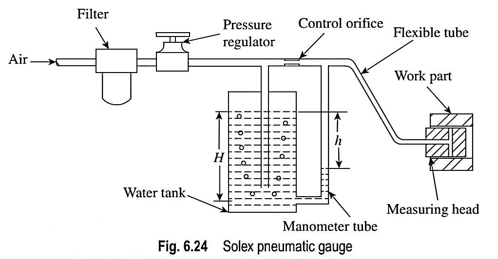
  • The Solex pneumatic gauge is one of the most popular pneumatic comparators in the industry.
  • The Solex pneumatic gauge is generally used for the inspection of internal dimensions, although it is also used for external
  • measurements with suitable attachments.
  • Figure illustrates the construction details of this comparator.
  • Compressed air is drawn from the factory air supply line, filtered, and regulated to a pressure of about 2 bar.
  • Air will now pass through a dip tube immersed in a glass water tank.
  • The position of the dip tube in terms of depth H will regulate the effective air pressure in the system at the input side.
  • Extra air, by virtue of a slightly higher supply air pressure, will leak out
  • of the water tank in the form of air bubbles and escape into the atmosphere.
  • This ensures that the air moving towards the control orifice will be at a desired constant pressure.
  • The air at a reduced pressure then passes through the control orifice and escapes from the measuring orifice in the measuring head.
  • Based on the clearance between the work part and the measuring orifice, a back pressure is created, which results in the head of water being displaced in the manometer tube.
  • We know that. within a limited measuring range, change in pressure varies linearly with change in internal dimension of the work part.
  • Therefore, the change in linear dimension can be directly read from a linearly calibrated scale.
  • The Solex comparator has a high degree of resolution, and variation in dimension up to a micrometre can be determined easily.
  • Amplification of up to 50,000 is obtainable in this gauge.
  •  


  • Working principle of optical comparator is based on the laws of light reflection and refraction.
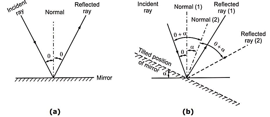
  • According to the law of reflection, the angles of incidence and reflection are equal, when the reflection occurs on a plane surface (mirror), i.e. the angle between incident ray and normal (1) to the mirror surface (
    ) is equal to angle of reflected ray and normal (1) to the mirror surface (
    ). And total angle between incident ray and reflected ray is 2
    . Refer Fig. (a).
  • Now, if the reflecting surface (mirror) is tilted through an angle
    , then normal (2) also moves through this angle
    .
  • Then, as shown in Fig. (b), the angle between incident ray and normal (2) becomes (
    +
    ).
  • According to law of reflection, the angle between reflected ray (2) and normal (2) should be equal to angle between incident ray and normal (2).
  • Therefore, angle between reflected ray (2) and normal (2) should also be (
    +
    ).
  • Thus, total angle between incident ray and reflected ray (2) will be 2 × (
    +
    ).
  • Thus, there is an increase of 2
    in the total angle and double magnification is obtained.
  • A beam of light passes through a graticule, which is engraved with a scale.
  • The rays from monochromatic source of light are incident on movable mirror through condenser.
  • These rays are passed to the fixed mirror by reflection, from where, they are again reflected to first mirror and then to the eyepiece.
  • This double reflection gives magnification.
  •  

  • If a standard/reference job is placed under plunger, the reference positions can be fixed.
  • Now, if an undersize or oversize job is placed instead of standard/reference job under the plunger, then due to different size of job, the plunger movements will cause the movable mirror to deflect.
  • Therefore, the variations can be measured by the graticule position through eyepiece.
  •  


  • An LVDT provides an alternating current (AC) voltage output proportional to the relative displacement of a transformer core with respect to a pair of electrical windings.
  • It provides a high degree of amplification and is very popular because of its ease of use.
  • Moreover, it is a non-contact-type device, where there is no physical contact between the plunger and the sensing
  • element.

  • Therefore, friction is avoided, resulting in better accuracy and long life for the comparator.
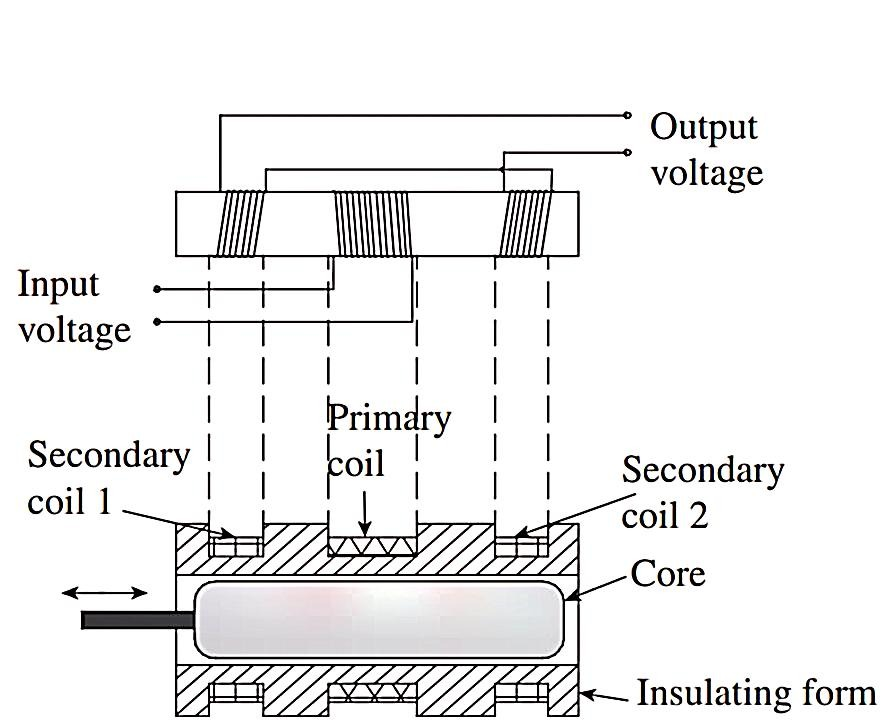
  • Figure illustrates the construction of an LVDT.
  • An LVDT produces an output proportional to the displacement of a movable core within the field of several coils.
  • As the core moves from its ‘null’ position, the voltage induced by the coils change, producing an output representing the difference in induced voltage.
  • It works on the mutual inductance principle.
  • A primary coil and two secondary coils, identical to each other, are wound on an insulating form, as shown in Fig.
  • An external AC power source is applied to the primary coil and the two secondary coils are connected together in phase opposition.
  • In order to protect the device from humidity, dust, and magnetic influences, a shield of ferromagnetic material is spun over the metallic end washers.
  • The magnetic core is made of an alloy of nickel and iron.
  • The motion of the core varies the mutual inductance of secondary coils.
  • This change in inductance determines the electrical voltage induced from the primary coil to the secondary coil.
  • Since the secondary coils are in series, a net differential output results for any given position of the core.
  • An output voltage is generated when the core moves on either side of the null position.
  • Theoretically, output voltage magnitudes are the same for equal core displacements on either side of the null balance.
  • However, the phase relation existing between power source and output
  • changes 180° through the null.

  • Therefore, it is easy, through phase determination, to distinguish
  • between outputs resulting from displacements on either side of the null.

  • For such displacements, which are within the linear range of the instrument, output voltage is a linear function of core displacement.
  •  


  • During measurements of various parameters of screw thread, it is necessary to find out errors occurred in five basic elements like, major diameter, minor diameter, effective diameter pitch and angle of thread.
  • These errors may lead to rejection of threads.
  • Thread errors in each element are discussed in brief as under:
  • (a)  Major and minor diameter errors:

  • Error in the major diameter or minor diameter may cause interference
  • between mating threads or a reduction in the flank contact.

  • This may cause component weakness.
  • Errors in major diameters or minor diameters of threads are generally caused by error in machine setting.
  • (b) Effective diameter error:

  • Errors in effective diameter will cause either 'interference between the thread flanks' or 'general slackness of fit between mating parts'.
  • If the major and minor diameters are at the maximum limit, and the effective diameter is below the minimum limit, then the thread will be thin on an external screw and thick on an internal screw.
  • (c) Pitch errors:

  • Pitch errors in threads include Periodic, Drunkenness, Progressive and Erratic or Irregular types of errors.
  • Pitch error occurs, if the ratio of the linear velocity of tools and angular velocity of the work is not maintained constant and correct.
  • The total Pitch Error in overall length of the thread is called as Cumulative Pitch Error.
  • Periodic Errors
  • When the errors vary in magnitude and are recurring at regular intervals, they are known as periodic errors.
  • This error repeats itself at regular intervals along the successive portions of thread being longer or shorter than the mean.
  • Pitch of the thread is not uniform and pitch increases to a maximum, then reduces through the normal value to a minimum value and so on.
  • Therefore, the graph between the cumulative pitch error and length of threads of this error is sinusoidal.
  • Such errors are caused due to,
  • (a) Non-uniform tool work velocity ratio.

    (b) Lack of lead screw squareness, while cutting the thread.

    (c) Eccentric mounting of the gears between the lead screw and spindle.

    (d) Error in the teeth of gears between the lead screw and spindle.


    ii.            Drunkenness or Drunken Thread Error

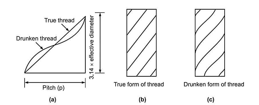
  • Drunkenness is also known as drunken-thread. It is a particular case of periodic error.
  • In this error, the pitch measured parallel to the thread axis will always be correct; the only error is that, the thread is not cut to true helix.
  • The profile of helix will be a curve in the case of drunken thread and not a straight line as shown in Fig.
  • Here,
    is the helix angle.
  • Drunken thread is the one having erratic pitch. Erratic pitch does not follow regular pattern.
  • The advance of helix is irregular in one complete revolution of the thread.
  • The pitch of the thread is not uniform. It varies in magnitude over equal fractions of each turn of the thread.
  • It is very difficult to determine such errors.
  • They may arise due to disturbances in the machine set up, variation in the cutting properties of material etc.
  •  

    iii.            Progressive Pitch Error

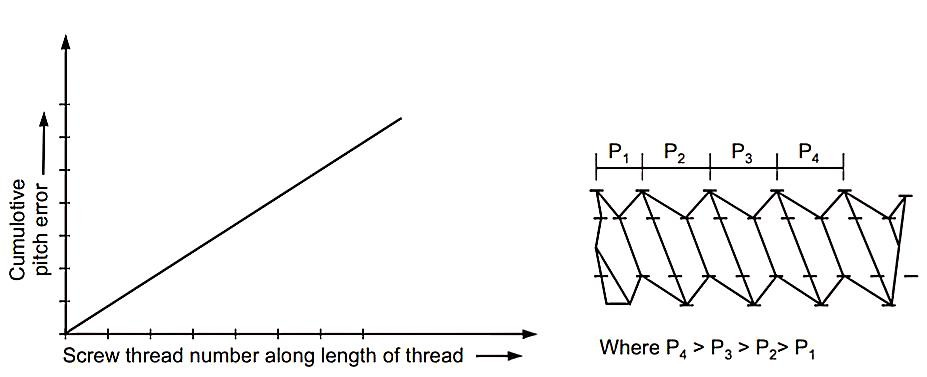
  • Progressive pitch error is uniform and gradual, but giving pitch value either a greater or smaller than nominal value as shown in Fig.
  • The cumulative pitch error increases with the increase in length of thread.
  • Such errors are caused due to,
  • (a)  Incorrect ratio of the linear velocity of tool and angular              

    velocity of the work.

    (b) Pitch error in the lead screw of lathe or other machine

    used for thread cutting.

    (c)  Use of incorrect gear or gear train between work and

    lead screw..


    iv.            Irregular or Erratic Errors

  • When the pitch varies irregularly along the length of thread, the types of errors found are called as irregular erratic pitch error.
  • They are caused due to,
  • (a) Machine faults.

    (b) Disturbances in the machining set up,

    (c) Variations in the cutting properties of the material etc.

    (d) Irregular cutting action resulting from non-uniformity in the material of the screw.

  • They have no specific characteristic and specific causes.
  • Therefore, they cause erratic and irregular variations in pitch over different length of thread.
  •  


  • Measurement of Minor Diameter
  • The best way of measuring a minor diameter is to measure it using a floating carriage micrometer.
  • The carriage has a micrometer with a fixed spindle on one side and a movable spindle with a micrometer on the other side.
  • The carriage moves on a finely ground ‘V’ guideway or an anti-friction guideway to facilitate movement in a direction parallel to the axis of the plug gauge mounted between centers.
  • The micrometer has a non-rotary spindle with a least count of up to 0.001 or 0.002 mm.
  • Minor diameter is measured by a comparative process, wherein small V-pieces that make contact at the root of the threads are used.
  • The selection of V-pieces should be such that the included angle of a V-piece is less than the angle of the thread.
  • V-pieces are placed on each side of the screw with their bases against the micrometer faces.
  • The initial reading is taken by mounting a setting cylinder corresponding to the dimension being measured.
  • Then, the threaded workpiece is mounted between the centers and the reading is taken.
  • The difference in the two readings directly gives the error in the minor diameter.
  •  

     2. Measurement of Major Diameter

  • The simplest way of measuring a major diameter is to measure it using a screw thread micrometer.
  • While taking readings, only light pressure must be used, as the anvils make contact with the screw solely at points and any excess application of pressure may result in a slight deformation of anvil due to compressive force, resulting in an error in the measurement.
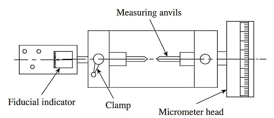
  • However, for a more precise measurement, it is recommended to use a bench micrometer shown in Fig.
  • A major advantage of a bench micrometer is that a fiducial indicator is a part of the measuring system.
  • It is thus possible to apply a pressure already decided upon by referring to the fiducial indicator.
  • However, there is no provision for holding the workpiece between the centers, unlike a floating carriage micrometer.
  • The inspector has to hold the workpiece by hand while the readings are being taken.
  • The machine is essentially used as a comparator.
  • To start with, the anvil positions are set by inserting a setting cylinder.
  • A setting cylinder serves as a gauge and has a diameter that equals the OD of the screw thread being inspected.
  • Now, the setting cylinder is taken out, the workpiece is inserted between the anvils, and the deviation is noted down on the micrometer head.
  • Since the position of the fixed anvil will remain unaltered due to the setting of the fiducial arrangement, the movable anvil will shift axially depending on the variation in the value of OD of the screw being inspected.
  • In order to sense deviations on either side of the preset value, the movable anvil will always be set to a position, which can detect small movements in either direction.
  • The error, as measured by the micrometer head, is added to or subtracted from the diameter of the setting cylinder to get the actual value of OD.
  • Measurement of the OD of internal threads is trickier, as it is difficult to take measurements using conventional instruments.
  • An easier option is to employ some indirect measurement techniques.
  • A cast of the thread is made, which results in a male counterpart of the internal thread.
  • Now, the measurement can be carried out using techniques used for external threads. The cast may be made of plaster of Paris or wax.
  •  

    3. Measurement of Effective Diameter

  • Effective diameter of a screw thread is the diameter of the pitch cylinder, which is coaxial with the axis of the screw and intersects the flanks of the threads in such a way so as to make the width of threads and widths of spaces between them equal.
  • Thread measurement by wire method is a simple and popular way of measuring an effective diameter.
  • Small, hardened steel wires (best-size wire) are placed in the thread groove, and the distance over them is measured as part of the measurement process.
  • There are three methods of using wires: one-wire, two-wire, and three-wire methods.
  • Three-wire Method

  • The three-wire method is an extension of the principle of the two-wire method.
  • As illustrated in Fig. a three wires are used to measure the value of M, one wire on one side and two wires on adjacent thread flanks on the other side of the screw.
  • Measurement can be made either by holding the screw, wires, and micrometer in hand or by using a stand with an attachment to hold the screw in position.
  • Since three wires are used, the micrometer can be positioned more accurately to measure M, the distance over the wires.
  • With reference to Fig. b, let M be the distance over the wires, E the effective diameter of the screw, d the diameter of best-size wires, and H the height of threads.
  • Now, OC = OA cosec (x/2) = d/2 cosec (x/2)

    H = p/2 cot (x/2) and, therefore, BC = H/2 = p/4 cot (x/2)

    If h is the height of the center of wire from the pitch line,

    then h = OC BC.

    h = d/2cosec (x/2) p/4 cot (x/2)

    Distance over wires, M = E + 2h + 2r,

    where r is the radius of the wires.

    Therefore, effective diameter

    E = M d cosec (x/2) + p/2 cot (x/2) d

    E = M d[1 + cosec (x/2)] + p/2cot (x/2)


    4.     Measurement of pitch
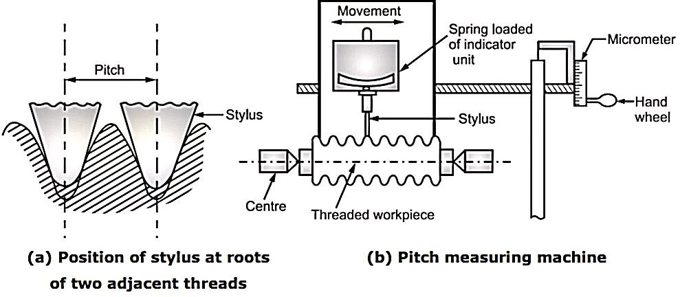
  • Pitch measuring machine is used to measure the pitch error of individual threads accurately.
  • The stylus of indicator unit is set in groove of thread, such that, indicator unit shows zero reading.
  • Indicator unit is carried on a slide mounted on balls, so that, it can move along the thread axis.
  • It employs various stylus points to suit the different forms and profiles of screw threads, which are to be checked.
  • The screw under measurement is held stationary between centers on the machine, located at headstock and tailstock.
  • The slide is actuated by means of a micrometer. When the micrometer spindle is, rotated, the indicator unit along with its stylus resting in groove will move parallel to thread axis.
  • During movement of indicator unit from one groove of thread to another groove of adjacent thread, the stylus will move in and out of each successive thread.
  • When the stylus is moving over the flanks due to micrometer rotation, the indicator unit will show variations in reading.
  • As soon as, the stylus tests in the groove of adjacent thread, the indicator unit should show zero reading.
  • Micrometer reading is taken during this travel of indicator, unit along with stylus.
  • The micrometer reading is taken each time, when stylus moves from groove of one thread to groove of next thread.
  • If there are variations in the readings show the pitch error of each thread of the screw.
  • Special graduated discs are provided to fit the micrometer to suit all pitches.
  • The small handwheel below the micrometer screw serves the purpose of moving the indicator with its stylus in contact with each thread profile along the length of threaded screw.
  • The total travel of the micrometer is 25 mm.
  • This method is able to read the smallest pitch errors of order 0.002 mm.
  •  


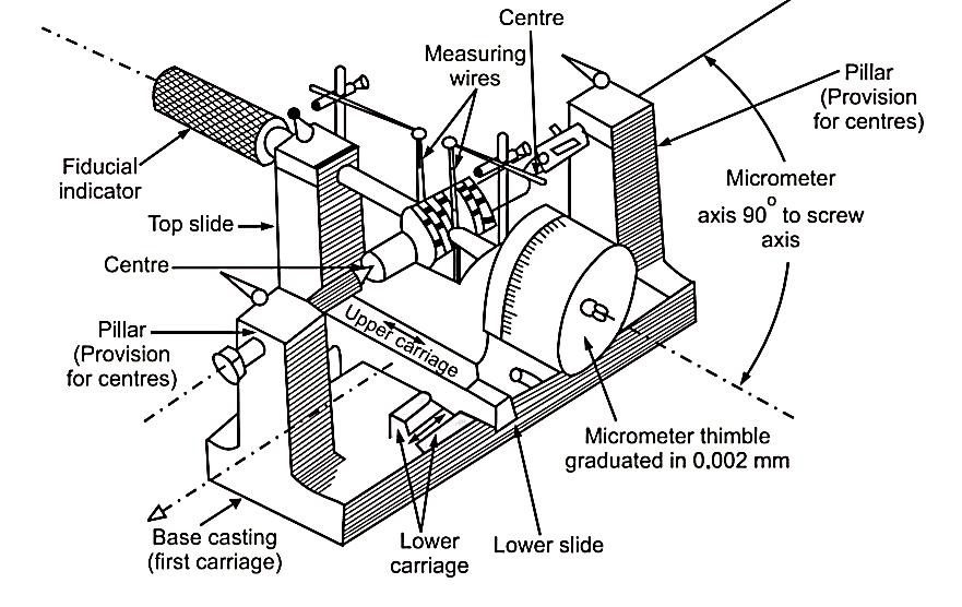
    Floating Carriage Dial Micrometer is also commonly known as “effective diameter

    measuring micrometer” or “floating carriage diameter measuring machine”,

    working on micrometer principle (screw and nut).

    • In fact, floating carriage diameter measuring is the bench micrometer mounted

    on a carriage machine.

    Working Principle:

  • When drum of micrometer rotates by one revolution, it will move forward by a distance equal to pitch of an internal thread. This movement is measured by using number of divisions engraved on drum and main scale.
  • This instrument is used for accurate measurement of 'Thread Plug Gauges'. Most important gauge dimensions such as Major diameter, Effective diameter, and Minor diameter are measured with the help of this instrument.
  • All these dimensions have a vital role in the thread plug gauges, since the accuracy and interchangeability of the component depends on the gauges used.
  • To reduce the effect of slight errors in the micrometer screws and measuring faces, this micrometer is basically used as comparator.
  • Construction:

    • Features of Floating carriage diameter measuring machines are,

    (a) Robust or sturdy cast iron base.

    (b) Suitable for dimensional stability.

    (c) Internal ways ground (finished by grinding) to finest accuracy.

    (d) Micrometer least count of the order 0.002 mm with non-rotary spindle.

    Metrology and Quality Control 5.7 Screw Thread Measurements

    • The machine consists of three units,

    (a) A base casting carries a pair of accurately mounted and aligned centers, on

    which the threaded workpiece is mounted i.e. first carriage.

    (b) Second carriage known as lower carriage is mounted on the first carriage at

    exactly 90°. It is capable to move parallel to thread axis.

    (c) Third carriage known as upper carriage is mounted on the second carriage/

    lower carriage. This upper carriage is capable to move at 90° to the thread

    axis due to provision of V-ball slides.

    • Upper carriage has micrometer thimble with graduated cylindrical scale at one

    end. Micrometer thimble can read upto 0.002 mm. On another end, a fiducial

    indicator is used in placed of fixed anvil, to perform all measurements at same

    pressure. Both, micrometer thimble and fiducial indicator have special

    exchangeable anvils made to suit the form of thread.


    From a metrological point of view, the major types of errors are as follows:

  • Gear blank runout errors
  • Gear machining is done on the gear blank, which may be a cast or a forged part.
  • The blank would have undergone preliminary machining on its outside diameter (OD) and the two faces.
  • The blank may have radial runout on its OD surface due to errors in the preliminary machining.
  • In addition, it may have excessive face runout.
  • Unless these two runouts are within prescribed limits, it is not possible to meet the tolerance requirements at later stages of gear manufacture.
  • 2.     Gear tooth profile errors

  • These errors are caused by the deviation of the actual tooth profile from the ideal tooth profile.
  • Excessive profile error will result in either friction between the mating teeth or backlash, depending on whether it is on the positive or negative side.
  •  

    3.     Gear tooth errors

  • This type of error can take the form of either tooth thickness error or tooth alignment error.
  • The tooth thickness measured along the pitch circle may have a large amount of error.
  • On the other hand, the locus of a point on the machined gear teeth may not follow an ideal trace or path.
  • This results in a loss in alignment of the gear.
  • 4.     Pitch errors

  • Errors in pitch cannot be tolerated, especially when the gear transmission system is expected to provide a high degree of positional accuracy for a machine slide or axis.
  • Pitch error can be either single pitch error or accumulated pitch error.
  • Single pitch error is the error in actual measured pitch value between adjacent teeth.
  • Accumulated pitch error is the difference between theoretical summation over any number of teeth intervals and summation of actual pitch measurement over the same interval.
  •  

    5.     Runout errors

  • This type of error refers to the runout of the pitch circle.
  • Runout causes vibrations and noise, and reduces the life of the gears and bearings.
  • This error creeps in due to inaccuracies in the cutting arbour and tooling system.
  •  

    6.     Lead errors

  • This type of error is caused by the deviation of the actual advance of the gear tooth profile from the ideal value or position.
  • This error results in poor contact between the mating teeth, resulting in loss of power.
  •  

    7.     Assembly errors

  • Errors in assembly may be due to either the center distance error or the axes alignment error.
  • An error in center distance between the two engaging gears results in either backlash error or jamming of gears if the distance is too little.
  • In addition, the axes of the two gears must be parallel to each other, failing which misalignment will be a major problem.

  • Since tooth thickness is a length of arc, it cannot be measured directly.
  • Therefore in most cases, it is sufficient to measure chordal thickness.
  • To measure the chordal thickness, gear tooth vernier caliper is used.
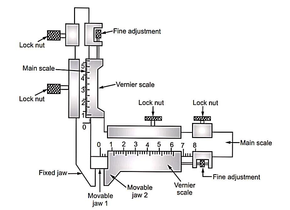
  •  The gear tooth vernier caliper consists of two perpendicular vernier arms with vernier scale on each arm.
  • One Vernier arm (vertical) is used for setting the jaws at proper death 'd' from top of tooth, whereas, second arm (horizontal) is used for measuring tooth thickness.
  • The caliper is so set that, it slides or resets on the top of gear tooth and lower ends of caliper jaws touch the flanks or sides of tooth at pitch circle.
  • The reading on horizontal vernier scale gives the value of chordal thickness (w) reading on vertical vernier scale gives chordal addendum (d).
  • These measured values by the gear tooth vernier caliper are compared with the theoretical values.
  • Theoretical values are calculated by using the following formula
  • w = N H m sin

    d =

  • Tooth thickness is specified by an arc distance AEB and ‘w’ is chord ADB and also distance ‘d’ is slightly greater than the addendum CE.
  • Therefore ‘w’ is called as chordal thickness and ‘d’ is called chordal addendum.

  • In gear tooth caliper method, both the chordal thickness and chordal addendum are dependent upon number of teeth.
  • Now, if number of teeth on gears is different in a single set of gears to be measured, then number of teeth of every gear must be known to calculate the chordal thickness and chordal addendum.
  • Thus, measurement of various parameters of different gears in a single set would involve separate calculations. Thus, the process becomes laborious and time consuming.
  • Constant chord method eliminates these problems.
  • Constant chord of a gear is measured, where the gear tooth flanks touch the flanks of basic rack.
  • Working Principle:

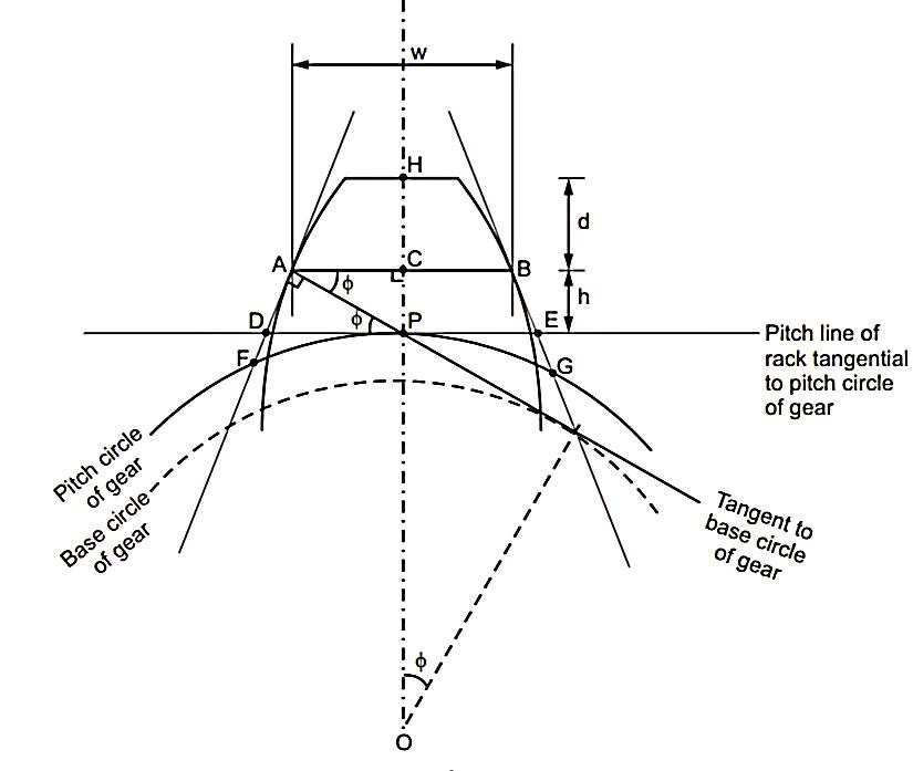
  • Teeth of basic rack are straight and inclined to their pitch line at pressure angle
    as shown in Fig.
  • The gear tooth and rack are in contact in symmetrical position of all num at the point of contact.
  • The distance AB remains constant. This distance ‘AB’ is referred as constant chord.
  • If the gear relates and all teeth come in contact with the rack, the contact occurs only at point A and B. This, is the reason why, AB is called as constant chord.
  • Also, we can see that ‘d’ is the vertical distance of chord ‘AB’ from top face of tooth. [Point 'H'].
  • In constant chord method of tooth thickness measurement, it is essential that,
  • (a) Pitch line of rack is tangent to pitch circle of gear

    (b) [Tooth thickness of rack measured along its pitch line] = [ Arc tooth thickness             

                                                                                                               of gear tooth measured                             

                                                                                                                   along its pitch circle] Distance 'DE' = Arc distance 'FG'

  • Constant chord 'AB' is measured, when the flanks of gear tooth touch the flanks of basic rack.
  • Constant chord is defined as ‘the chord joining those points located on opposite sides of faces of a gear tooth, which make, contact with the mating teeth of rack, when the pitch line of rack is tangent to pitch circle of gear'.
  • The values of distance AB (‘w’) and its depth (d) from top of tooth can be measured by suitable measuring instrument.
  • These measured values are then compared and verified with their theoretical values.
  • Theoretical values can be calculated by using following formulae,
  • Constant chord (AB) 'w' =

    Depth ‘d’ = m

    Where m = module & pressure angle


  • Measurement of tooth thickness using the gear tooth vernier does not give very accurate
  • (i) the measurement depends upon two vernier readings, each of which, is a function of other and

    (ii) the measurement is made the faces of its measuring jaws, which itself are the causes of inaccurate measurements.

    (iii) comparatively more sensitive than chordal thickness method.

    (iv) This method does not depend on number of teeth.

  • These problems can be overcome by measuring the span of selected number of teeth.
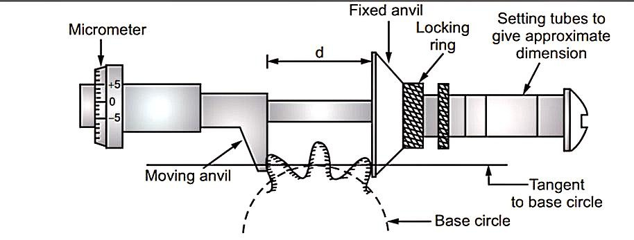
  • The span length is tangent to the base circle and therefore it is called as base tangent length.
  • The base tangent method uses a single vernier caliper.
  • The measuring instrument is known as base tangent comparator. It consists of two flanked anvils, one fixed and other moving.
  • Moving anvil carries a micrometer having limited movement on either side of zero setting.
  • Base tangent length (d) is calculated with the help of following formula,
  • d =

    where, N = Number of teeth

    m = Module

    S = Number of teeth between two anvils

    = Pressure angle

  • This theoretically calculated value of base tangent length (d) is then set in the tangent comparator using a suitable combination of slip gauges as shown in Fig.
  • This theoretically calculated value of base tangent length is set in between the anvils of comparator using a slip gauge combination.
  • This becomes the standard for the comparator.
  • Now, the gear span distance is checked practically with this tangent comparator and variation from the theoretical value can be read on micrometer dial provided on the device.

  • Composite errors such as errors in tooth form, pitch, concentricity of pitch line etc. can be checked by rolling gear test.
  • This method is used to distinguish the two gears manufactured in two categories.
  • (i)                Acceptable, (ii) Rejectionable, before leading to assembly section.

  • The system consists of two carriages (one fixed and other movable) mounted on a base.
  • The fixed carriage is locked at one position.
  • Master gear is mounted on the spindle of fixed carriage.
  • The movable carriage is spring loaded and it is held towards the fixed carriage.
  • Gear under test is mounted on the spindle of movable carriage, such that, master gear and gear under test, both are in mesh.
  • A dial gauge indicator is made to rest against movable carriage.
  • Now, the master gear and gear under test, in mesh, are rotated by hand and variations in the dial gauge readings are observed.
  • If there is no variation seen in the dial gauge reading, then the gear under test is to be perfect.
  • But, if variations in dial gauge readings are found and variations fall outside the permissible limits, then the gear is rejected.
  • Only acceptable gears are sent for assembly, due to which, unnecessary expenses in assembly section can be saved.
  • In addition to cost, great amount of trouble caused due to gears running with noise is avoided.
  • Advantages of Rolling Gear Test

  • Most commonly used test under production conditions.
  • Less time consuming.
  • Accurate results.
  • Composite error due to error in tooth form, pitch, concentricity of pitch line etc. can be determined.

  • The profile projector, also called the optical projector, is a versatile comparator, which is widely used for the purpose of inspection.
  • It is especially used in tool room applications.
  • It projects a two-dimensional magnified image of the workpiece onto a viewing screen to facilitate measurement.
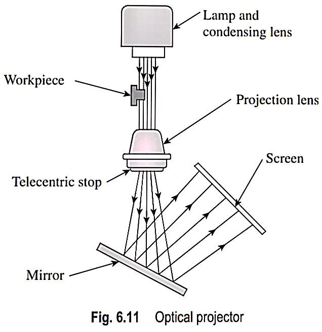
  • It comprises three main elements: The projector itself comprising a light source and a set of lens housed inside the enclosure, a work table to hold the workpiece in place, and a transparent screen with or without a chart gauge for comparison or measurement of parts.
  • Figure illustrates the various parts of an optical projector.
  • The workpiece to be inspected is mounted on a table such that it is in line with the light beam coming from the light source.
  • The table may be either stationary or movable.
  • In most projectors, the table can be moved in two mutually perpendicular directions in the horizontal plane.
  • The movement is effected by operating a knob attached with a double vernier micrometer, which can provide a positional accuracy of up to 5 μm or better.
  • The light beam originating from the lamp is condensed by means of a condenser and falls on the workpiece.
  • The image of the workpiece is carried by the light beam, which passes through a projection lens.
  • The projection lens magnifies the image, which falls on a highly polished mirror kept at an angle.
  • The reflected light beam carrying the image of the workpiece now falls on a transparent screen.
  • Selecting high-quality optical elements and a lamp, and mounting them at the right location will ensure a clear and sharp image, which, in turn, will ensure accuracy in measurement.
  • The most preferred light source is the tungsten filament lamp, although mercury or xenon lamps are also used sometimes.
  • An achromatic collimator lens is placed in the path of a light beam coming from the lamp.
  • The collimator lens will reorient the light rays into a parallel beam large enough in diameter to provide coverage of the workpiece.
  • Mounting and adjustment of the lamp are critical to assure proper positioning of the filament with respect to the optical axis.
  • The collimated beam of light passes across the area the workpiece is positioned on the work table.
  • Care should be taken to ensure that the contour of the workpiece that is of interest is directly in line with the light beam.
  • The distance of the table from the projection lens should be such that it matches with the focal length of the lens, in order to ensure a sharp image.
  • The table can be either stationary or movable.
  • The movable tables are designed to generally travel in two mutually perpendicular directions in the horizontal plane.
  • The table moves on anti-friction guide-ways and is controlled by the knob of a double vernier micrometer.
  • This micrometer provides an accurate means of measuring the dimensions of the workpiece.
  • The light beam, after passing through the projection lens, is directed by a mirror onto the viewing screen.
  • Screens are made of glass, with the surface facing the operator, ground to a very fine grain size.
  • The location of the screen should be such that it provides an accurate magnification and perfectly conforms to the measurement indicated by the micrometer.
  • A reticle attached to the end of the projection lens provides images of two mutually perpendicular cross-wires, which can be used for the purpose of measurement.  
  • Many projector screens can also be rotated about the center, thereby enabling measurement of angular surfaces also.
  • The following are the typical applications of profile projectors:
  • 1. Inspection of elements of gears and screws

    2. Measurement of pitch circle diameters of holes located on components

    3. Measurement of unusual profiles on components such as involute and cycloidal, which are difficult to measure by other means

    4. Measurement of tool.
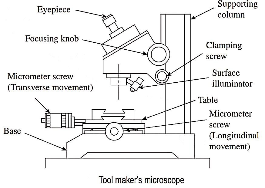


  • The tool maker’s microscope is a multifunctional device that is primarily used for measurement on factory shop floors.
  • Designed with the measurement of workpiece contours and inspection of surface features in mind, a tool maker’s microscope supports a wide range of applications from shop floor inspection, and measurement of tools and machined parts to precision measurement of test tools in a measuring room.
  • The main use of a tool maker’s microscope is to measure the shape, size, angle, and position of small components that fall under the microscope’s measuring range.
  • Figure illustrates the features of a typical tool maker’s microscope.
  • It features a vertical supporting column, which is robust and carries the weight of all other parts of the microscope.
  • The workpiece is loaded on an XY stage, which has a provision for translatory motion in two principal directions in the horizontal plane.
  • Micrometers are provided for both X and Y axes to facilitate linear measurement to a high degree of accuracy.
  • The entire optical system is housed in the measuring head.
  • The measuring head can be moved up and down along the supporting column and the image can be focused using the focusing knob.
  • The measuring head can be locked into position by operating the clamping screw.
  • An angle dial built into the eyepiece portion of the optical tube allows easy angle measurement.
  • A surface illuminator provides the required illumination of the object, so that a sharp and clear image can be obtained.
  • The element that makes a microscope a measuring instrument is the reticle.
  • When the image is viewed through the eyepiece, the reticle provides a reference or datum to facilitate measurement.
  • Figure illustrates the procedure for linear measurement.
  • A measuring point on the workpiece is aligned with one of the cross-wires and the reading R1 on the microscope is noted down.
  • Now, the XY table is moved by turning the micrometer head, and another measuring point is aligned with the same cross-wire.
  • The reading, R2 is noted down. The difference between the two readings represents the dimension between the two measuring points.
  • Since the table can be moved in two mutually perpendicular direction using the micrometers, a precise measurement can be obtained.
  • While the eyepiece is inserted in an eyepiece mount, the objective lens can be screwed into the optical tube.
  • The reticle is also inserted in the eyepiece mount.
  • A positioning pin is provided to position the reticle accurately.
  • A dioptre adjustment ring is provided in the eyepiece mount to bring the cross-wires of the reticle into sharp focus.
  • The measuring surface is brought into focus by moving the optical tube up and down, with the aid of a focusing knob.
  • Looking into the eyepiece, the user should make sure that the cross-wires are kept in ocular focus during the focusing operation.
  • Positioning of the workpiece on the table is extremely important to ensure accuracy in measurement.
  • The measuring direction of the workpiece should be aligned with the traversing direction of the table.
  • While looking into the eyepiece, the position of the eyepiece mount should be adjusted so that the horizontal cross-wire is oriented to coincide with the direction of the table movement.
  • Now, the eyepiece mount is firmly secured by tightening the fixing screws.
  • The workpiece is placed/clamped on the table and the micrometer head turned to align an edge of the workpiece with the center of the cross-wires.
  • Then, the micrometer is operated and the moving image is observed to verify whether the workpiece pavement is parallel to the measuring direction.
  • By trial and error, the user should ensure that the two match perfectly.
  • Most tool maker’s microscopes are provided with a surface illuminator. This enables the creation of a clear and sharp image

  • 1. Primary texture

  • Surface irregularities of small wavelength are called primary texture or roughness.
  • They are called micro-geometrical errors.
  • Primary texture includes:
  • (i)                Irregularities of third order (irregularities due to feed marks of cutting tool) and

    (ii)              Irregularities of fourth order (irregularities due to rupture of material caused due to separation of chip).

  • Primary texture includes irregularities caused by direct action of cutting elements on materials.
  • Reasons for the above irregularities leading to primary texture:
  • (i)                Cutting tool shape,

    (ii)              Tool feed rate,

    (iii)           Friction,

    (iv)            Wear,

    (v)              Corrosion etc.
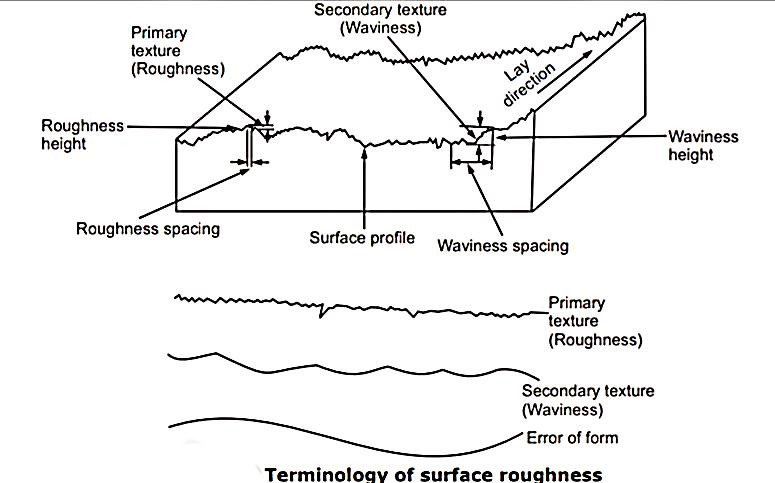
  • Evaluation of surface finish is based on height and character of micro geometrical irregularities.
  • 3                Secondary texture

  • Surface irregularities of considerable wavelength of a periodic character are called secondary texture or waviness.
  • In other words, secondary texture or waviness includes irregularities of larger wavelength.
  • They are called macro-geometrical errors.
  • Secondary texture includes
  • (i)                irregularities of first order, (irregularities due to lack of straightness of guide-ways of tool, deformation of work under cutting forces, weight of material itself) and

    (ii)              Second order (irregularities due to vibrations and chatter marks).

  • Roughness (primary texture) is superimposed upon the waviness (secondary texture).
  • Thus, any finished surface could be considered as combination of two forms of wavelength superimposed upon each other.

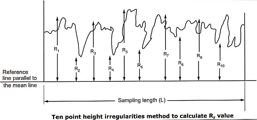
  • 1. Ten Point Height Method (Rz): 

  • Rz value is defined as, "the average difference between five highest peaks and five lowest valleys of surface texture within sampling length, measured from a reference line parallel to mean line and not crossing the profile".
  • Rz value = 1/ 5 {(R1 + R3 + R5 + R7 + R9 ) (R2 + R4 + R6 + R8+ R10 )} where, R1, R3 , R5, R7, R9 are highest peaks and R2, R4, R6, R8 and R10 are lowest valleys.
  • This method evaluates the total depth of surface irregularities within the sampling length. It denotes the amount of surface roughness.
  • But, it doesn’t give sufficient information about the surface, because shape of entire profile is neglected. It is used, when it is desired to control the cost of finishing for checking rough machining.
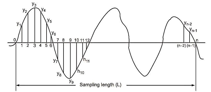
  • 2. R.M.S. Value:

  • Root mean square value is defined as, "square root of arithmetic mean values of squares of ordinates of surface measured from mean line"
  • Let us assume that, sampling length 'L' is divided into 'n' equal parts. Ordinates are points 1,2,3,……,n, whose heights are y1, y2, y3, …….. yn from meanline.
  • Then, RMS value =
  • 3.  Centre Line Average Method or CLA Value:

  • CLA value is defined as, "the average height of all ordinates of the surface from mean line, without considering algebraic signs".
  • It means that, heights below the mean line, such as, h7, h8, h9 … h12 and so on, should not be taken as negative. 
  • Let h1, h2, h3, …… hn be the readings, then,
  • CLA =

  • CLA value measure is preferred over RMS value measure, because its value can be easily determined using planimeter or graph.
  •  


  • The Taylor–Hobson Talysurf works on the same principle as that of the Tomlinson surface meter.
  • However, unlike the surface meter, which is purely a mechanical instrument, the Talysurf is an electronic instrument.
  • This factor makes the Talysurf a more versatile instrument and can be used in any condition, be it a metrology laboratory or the factory shop floor.
  • Figure  illustrates the cross section of the measuring head.
  • The stylus is attached to an armature, which pivots about the centre of piece of an E-shaped stamping.
  • The outer legs of the E-shaped stamping are wound with electrical
  • coils.
  • A predetermined value of alternating current (excitation current) is supplied to the coils.
  • The coils form part of a bridge circuit.
  • A skid or shoe provides the datum to plot surface roughness.
  • The measuring head can be traversed in a linear path by an electric motor.
  • The motor, which may be of a variable speed type or provided with a gear box, provides the required speed for the movement of the measuring head.
  • As the stylus moves up and down due to surface irregularities, the armature is also displaced.
  • This causes variation in the air gap, leading to an imbalance in the bridge circuit.
  • The resulting bridge circuit output consists of only modulation.
  • This is fed to an amplifier and a pen recorder is used to make a permanent record.
  • The instrument has the capability to calculate and display the roughness value according to a standard formula.
  • Numericals:

  • Calculate effective diameter & best wire size for M22 x 2.5 screw plug gauge by using floating carriage micrometer for which reading were taken as: Diameter of standard cylinder = 20mm. Micrometer reading over standard cylinder with two wire is = 15.9334mm, micrometer reading over plug series gauge with two wire is = 15.2245mm.
  •  

    Solution

    p = 2.5mm

    x = 600

    D1= 20mm

    R1= 15.9334mm

    R2= 15.2245mm


    Best wire size (d)

    d = p/2 sec (x/2)

       = 2.5/2 sec (30/2)

       = 1.443 mm

    Effective diameter (DE)

    Distance under wire (T) = D1 + (R2 - R1)

                                                = 20 + (15.2245 – 15.9334) = 19.2911 mm

    P = 0.866p – d

       = 0.866 x 2.5 – 1.443

       =0.722 mm

    DE = T +P = 19.2911 + 0.722 = 20.013 mm


    Reference:

  • Engineering Metrology & MeasurementsN. Raghavendra & L. Krishnamurthy
  • Metrology & Quality control – Vinod Thombre - Patil
  •  


    Index
    Notes
    Highlighted
    Underlined
    :
    Browse by Topics
    :
    Notes
    Highlighted
    Underlined