Back to Study material
Turbo Machines

Unit – 2

Impulse Water Turbines
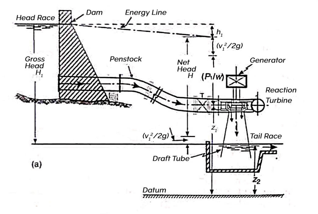

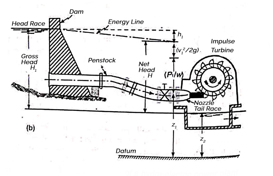
  • Figure shows a general layout of hydroelectric power plant which consists of
  •  A dam

    Penstock

    Turbine

    Tail race

  • One of the essential requirements of the hydroelectric power generation is the availability of a continuous source of water with large amount of hydraulic energy.
  • Such a source of water may be made available if natural lake or a reservoir may be found at a higher elevation or an artificial reservoir may be formed by constructing a dam across a river.
  • Figure shows general layout of a hydroelectric power plant in which an artificial storage reservoir phone by constructing a dam has been shown.
  • Water from storage reservoir is carried through penstock to the turbine.
  • Penstocks are the pipes of large diameter, usually made of steel wood or reinforced concrete, which carry water under pressure from the storage reservoir to the turbine.
  • Sometimes forebays are provided along the penstocks.
  • Forebays are storage reservoir which store water temporary when it is not required and supply the same when required.
  • When the power house is located just at the base of dam no forebay is required to be provided, however if the power house is situated away from the storage reservoir and water is carried to the power house through a canal. Then a forebay may be provided.
  • The water passing through the turbine is discharge to the tail race.
  • The tail race is the channel which carries water away from the power house after it has passed through the turbine.
  • It may be a natural stream channel or a specially excavated channel entering the natural stream at some point downstream from the powerhouse.
  • The water surface in the tail race channel is known as tail race level or simply tail race.
  •  


  • According to the type of energy at inlet
    1.  impulse turbine
    2.  reaction turbine
  • According to the direction of flow through runner.
    1. Tangential flow turbine
    2. Radial flow turbine
    3. Axial flow turbine
    4. Mixed flow turbine
  • According to head at inlet of turbine
    1. High head turbine
    2. Medium head turbine
    3. Low head turbine
  • According to specific speed of turbine
    1. Low specific speed turbine
    2. Medium specific speed turbine
    3. High specific speed of turbine
  •  


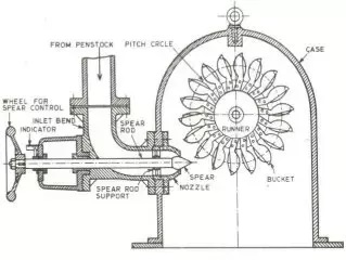
  • Figure shows the elements of a typical Pelton wheel installation.
  • The runner consists of a circular disc with number of buckets evenly spaced around its periphery.
  • The buckets have a shape of double semi ellipsoidal cups. Each bucket is divided into two symmetrical parts by a sharp edge ridge known as splitter.
  • One or more nozzles are mounted so that each directs a jet along a tangent to the circle through the centers of the buckets called the pitch circle.
  • The jet of water impinges on the splitter, which divides jet into two equal portions.
  • Each of which after flowing around the smooth inner surface at the buckets leaves it at its outer edge.
  • The buckets are so shape that the angle at the outlet tip varies from 10 degree to 20 degree so that the jet of water gets deflected through 160 degree to 170 degree.
  • The back of the bucket is so shape that as its swings downwards no water is wasted by splashing.
  • Further at the lower tip of the bucket a notch is cut which prevents jet striking the preceding bucket being intercepted by the next bucket very soon and is also avoid deflection of water towards the center of the wheel as the bucket first meets the jet.
  • For low heads buckets are made of cast iron and for high heads they are made of cast steel bronze or stainless steel.
  • In order to control the quantity of water striking the runner the nozzle fitted at the end of penstock provided with a spear or needle having a streamlined head which is fixed as shown in figure.
  • A casing made of cast iron or fabricated steel plates is usually provided for a Pelton wheel as shown in figure to prevent splashing of water and also to act as a safeguard against accidents.

  • In an impulse turbine all available energy of water is converted into kinetic energy or velocity head by passing it through a nozzle provided at the end of penstock.
  • The water coming out of the nozzle is formed into a free jet which impinges on a series of buckets of the runner does causing it to revolve.
  • The runner revolves freely in air.
  • The water is in contact with runner only a part of the runner at a time and throughout its action and its subsequent flow to the tale race the water is atmospheric pressure.
  • A casing however provided on the runner to prevent splashing and to guide the water discharge from buckets to tail race.
  •  


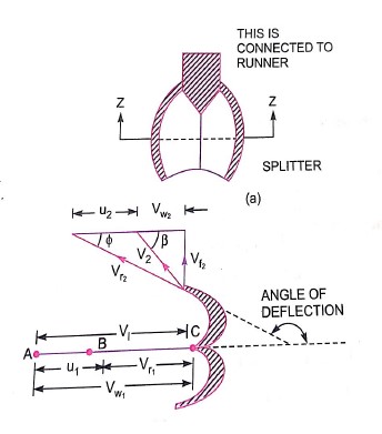
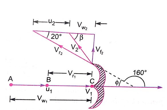
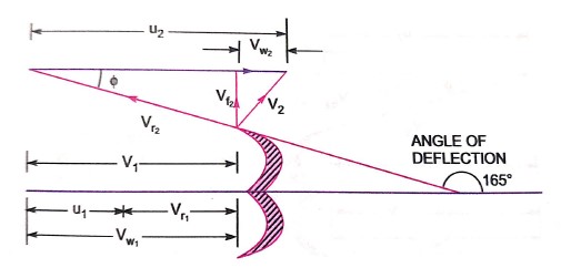
  • Figure shows the shape of the veins or buckets of the Pelton wheel.
  • The jet of water from the nozzle strike the bucket at the splitter which splits up the jet into two parts.
  • These parts of the jet glides over the inner surfaces and comes out at the outer edge. The splitter is the inlet tip and outer edge of the bucket is the outlet tip of the bucket.
  • The inlet velocity triangle is drawn at the splitter and outlet velocity triangle is drawn at the outer edge of the bucket.
  •  

    H= Net head acting on the Pelton wheel

         =

    Gross head

    Dia of penstock

    N= Speed of the wheel in r.p.m

    D= diameter of the wheel

    d=diameter of the jet

    Then, Velocity of jet at inlet

    The velocity triangle at inlet will be a straight line where

             =0   and   =0

    From the velocity triangular at outlet, we have

    The force exerted by the of water in the direction of motion is given by equation

    As the angle   is an acute angle, positive sign should be taken

    a=area of jet

    Work done by the jet on the runner per second

    Power given to the runner by the jet


    Work done per second per unit weight of water striking

    The energy supplied to the jet at inlet is in the form of kinetic energy and is equal to

    Kinetic energy of jet per second

    Hydraulic efficiency

                =


              u

    Now


         =


    The ideal velocity of jet usually known as spoutting velocity

    Actual velocity of the jet is slightly less due to friction loss in the nozzle

    Thus V =

    Where, Cv=coefficient of velocity

    Velocity of wheel u=

     Where Ku = speed ratio

                        = 0.43 to 0.47

    Angle through which jet of water gets deflected in buckets =1650

    Least diameter d of the jet

    Where Q = discharge through jet in

    Mean diameter D of Pelton wheel may be obtained as follows

    D=

    Jet ratio m=

    For maximum efficiency jet ratio should be from 11 to 14
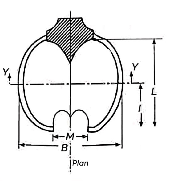
    Some of the main dimensions of the bucket of Pelton wheels as shown

    B= (4 to 5) d

    C= (0.81 to 1.05) d

    M=(1.1 to 1.25) d

    Angle  = 5° to 8°

    L= (2.4 to 3.2) d

    l= (1.2 to 1.9) d

       = 10° to 20°

    50 to 80

    Number of buckets = Z=


  • Important parameters which are varied during a test on a turbine
  • 1)     Speed (N)

    2)     Head (H)

    3)     Discharge (Q)

    4)     Power (P)

    5)     Overall efficiency (

    6)     Gate opening

  • Out of the above 6 parameters, three parameters namely speed head and discharge are independent parameters.
  • Out of the three independent parameters (N,H,Q) one of the parameter is kept constant and the variation of the other four parameters with respect to anyone of the remaining two independent variables are plotted and various are obtained.
  • These are called characteristic curves.
  • The following are the important characteristic curves of a turbine.
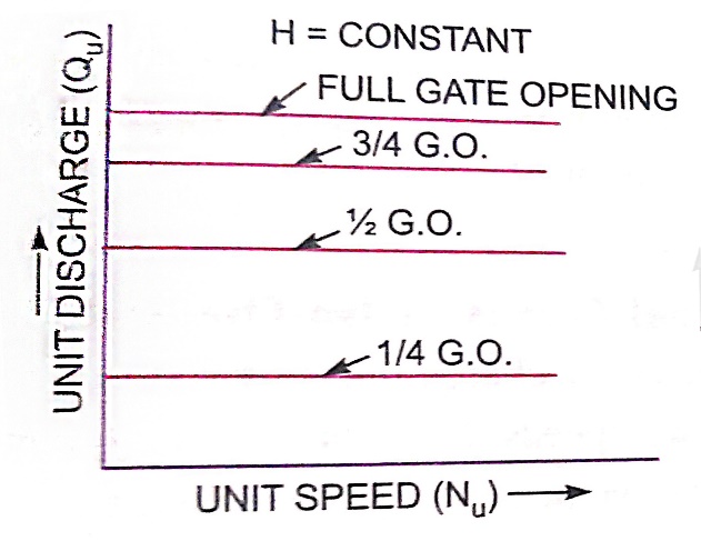
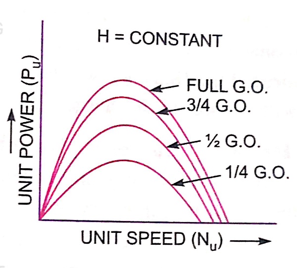
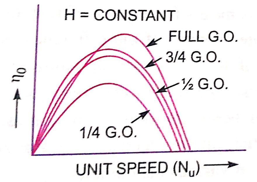
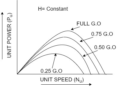
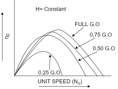
  • Constant head curves

  • These curves are obtained by keeping head constant and a constant gate opening on the turbine.
  • The speed of the turbine is varied by changing load on the turbine.
  • For each value of speed, the corresponding values of the power(P), discharge(Q) are obtained.
  • For a Pelton wheel

    For reaction turbines


  • Then the overall.
    or each value of the speed is calculated.
  • From these reading the values of unit speed
    ,unit power
    a determined.
  • Taking
    as abscissa, the values of
    are plotted as shown in figure by changing the gate opening, the values of
      are determined and taking
    as abscissa.
  • Figure a shows the main characteristic curves for Pelton wheel and figure b shows the main characteristic curves for reaction turbines.
  • Operating characteristic curves for constant speed curves
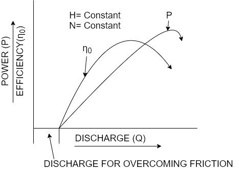
  • Operating characteristic curves are plotted when speed on the turbine is constant.
  • In case of turbines, the head is generally constant.
  • For operating characteristics N and H are constant and hence the variation of power and efficiency with respect to discharge Q are plotted.
  • The power curve for turbines shall not pass through the origin because certain amount of discharge is needed to produce power to overcome initial friction.
  • Hence the power and efficiency curves will be slightly away from the origin on the x-axis, as to overcome initial friction certain amount of discharge will be required.
  • Shows the variation of power and efficiency with respect to discharge.
  •  

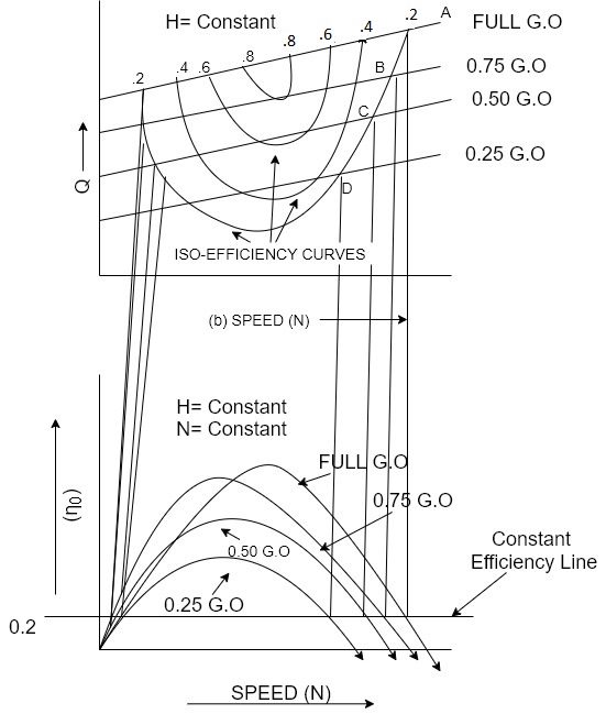
    Constant efficiency curves or Muschel curves or iso-efficiency curves

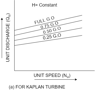
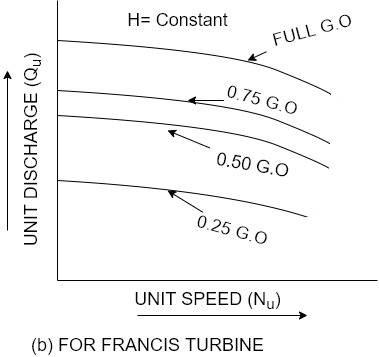
  • These curves are obtained from speed versus efficiency and speed versus discharge curves for different gate opening.
  • For a given efficiency from the
       curves, there are two speeds.
  • From
    curves, corresponding to two values of speeds there are two values of discharge.
  • Hence for a given efficiency there are two values of discharge for the particular gate opening.
  • This means for a given efficiency there are two values of speeds and two values of discharge for a given gate opening.
  • If the efficiency is maximum there is only one value.
  • These two values of speed and two values of discharge corresponding to particular gate opening are plotted as shown in figure.
  • The procedure is repeated for different gate opening and the curves Q vs N are plotted.
  • The points having the same efficiency are called iso- efficiency curves.
  • These curves are helpful for determining the  zone of constant efficiency and for predicting the performance of the turbine at various efficiencies.
  • For plotting the iso-efficiency curves horizontal lines representing the same efficiency are drawn on the  
        speed curves.
  • The points at which these lines cut the efficiency curves at various gate openings are transferred to the corresponding Q~ speed curves.
  • The points having the same efficiency are less then joined by a smooth curve.
  • These smooth curves represent the ISO efficiency curve.
  •  


  • It is defined as the speed of turbine which is identical in shape, geometrical dimensions, blade angles, gate opening etc. with actual turbine but of such size that it will develop unit power when working under until head.
  • It is denoted by symbol
  • Overall efficiency =

      =

    Where H=head under which the turbine is working

                 Q=discharge through turbines

                  P=power developed for shaft power

        P Q× H

    As and are constant …..(ii)

    D= diameter of actual turbine

    N=speed of actual turbine

    u=tangential velocity of the turbine

    Specific speed of turbine

    V=absolute velocity of water

    But.  u  V  where V  √H

             u √H      (iii)


    But. u=

            u  DN….(iv)

    From equation (iii) and (iv)

    √H.  DN

    Or D 

    Discharge Q= A×V

                  A B×D   


                    V √H


    Put the value of Q in equation (ii)

         ×H


       P=

    where K=constant of proportionality

    If P=1 and H=1 Speed N=Specific speed

    Put these values in above equation

    Or 

    Significance:-

  • Specific speed play an important role for selecting the type of the turbine.
  • Also performance of a turbine can be predicted by knowing the specific speed of the turbine.
  •  


    Following factors are considered for selecting a particular turbine at place

    1)     Head:- The net head under which the turbine is working plays an important role for selecting turbine.

    The type of turbine for different heads

    Net head in m

    Types of turbine

    300m or more

    Pelton turbine

    150m to 300m

    Pelton or Francis

      50m to 150m

    Francis turbine

      Less than 50 m

    Kaplan or propeller


    2)     Specific speed :- The specific speed is also an important factor for deciding the type of turbine to be installed at a place.

    Specific speeds

    Types of turbines

     85 to 30

    Pelton wheel with single jet

    31 to 50

    Pelton wheel with double jet

    51 to 225

    Francis

    256 to 860

    Kaplan or propeller


    3)     Part load operation :-

  • The turbines are not working always at full load.
  • There is considerable load variation.
  • At full load all the turbines are having approximately equal efficiency but at part load the efficiency of Kaplan and Pelton turbines are approximately equal to the efficiency of full load.
  • But the efficiency of Francis and propeller turbines are 60% of the efficiency at full load.
  • Hence the performance of Kaplan and Pelton turbines is better than Francis and propeller turbine.
  • 4) overall cost of installation and cavitation characteristics :-

  • The overall cost of installation of a turbine which consists of initial cost and running cost should be considered for selecting a type of turbine at site.
  • Also the cavitation characteristics for installation of reaction turbine should also be considered.
  •  


  • The power developed by single jet Pelton wheel is usually quite low.
  • This is because on account of the restrictions of the jet velocity, wheel speed.
  • A single jet cannot be made big enough to develop any desired power.
  • The amount of power developed by a single runner of a Pelton wheel turbine may however be increased by providing more than one jet spaced evenly around the same runner.
  • The nozzles must never be spaced so closely that water from one jet after striking runner interferes with another jet.
  • As such maximum number of jets for some large units are 6.
  • A Pelton wheel having more than one jet spaced around its runner is called multi jet Pelton wheel.
  • If P is the power developed by a Pelton wheel when working under head H and having only one jet, then the power developed by the multi jet Pelton wheel will be nP, if n jets are used for its working under the same head.
  • Sometimes even if by using more number of jets for a single runner the required power is not developed. Then a number of runners mounted on a common shaft may be used.
  • In some cases a combination of the above two systems may be used.
  •  


    Numericals :

    1. A Pelton turbine develops 3000 kW power under the head of 300 m. The overall efficiency of the turbine is 83%. If the ratio is 0.46 coefficients of nozzles

    i)                   diameter of the turbine

    ii)                 Diameter of the jet

    P=3000 kW

    H=300m

    Find D and d.

    Sol.

    16.5=

    N= 376.11 r.p.m

         = 0.98×√2×9.81×300

         = 75.18 m/s

     u=Ku

        = 0.45×√2×9.81×300

        =34.52 m/s


             D=1.75 m

               =


     Q=1.228

    Q = A×

    1.228 =

     d=0.144 m


    2.     The mean bucket speed of a Pelton wheel is 40 m/s and discharge is 1.2The head over the turbine is 385 m. The head loss due to friction in penstock is 9 m. The bucket deflects the jet through 165°. If coefficient of velocity of nozzle is 0.9, determine

    i)                   Power developed by the turbine

    ii)                 Hydraulic efficiency of turbine neglect bucket friction.

    Sol.

    u=                                                                

    Q= 1.2

    Hg=385m

    = 9m

      = 180-165=15°                        

    =0.9

    Net head available = H =

                                       = 385 - 9

                                       = 376 m
         =

         = 77.30m/s


          = 77.30-40

          = 37.30 m/s

    37.30 m/s


           =40 - 36.03

           = 3.97 m/s

       = u

                   =

                  =0.9817

                  =98.17%

    Power developed = Q

    =1000×1.2[77.30-3.97]

    =3.52×

    =3520 KW


    3.     A Pelton wheel is working under a head at 300m and mean bucket speed of 10m/s. Discharge through the turbine is 700 lit/sec. The buckets deflect the jet through an angle of 160°. Calculate power given by water to the runner and hydraulic efficiency of the turbine. Assume coefficient of velocity as also calculate overall efficiency and shaft power if mechanical efficiency is  85%.

    Sol. H=300m


         =

         = 75.18m/s

          = 75.18 - 10

          = 65.18m/s

                   = 61.25m/s

            = 61.25 - 10

            = 51.25m/s

    Power given by water to the runner

    (Runner power)=

                                =1000 x 0.7 [75.18 + 51.25] x 10

                                = 885.01

            =

            = 0.4473

            = 44.73%

    Shaft power = watts

    Overall efficiency=

                                          = 0.85 0.44

                                          = 0.374

                                      =37.4%

    Ques  

    4.     A Pelton wheel is to be designed for a head of 60m when running at 200 rpm . The Pelton wheel develops 95.6475 KW Shaft power the velocity of buckets =0.45 times the velocity of the jet , overall efficiency = 0.85 & coefficient of the velocity is equal to 0.98.

    Solution

    H=60m

    N=200m

    S.P.= 95.6475 KW

    u = 0.45 V

         =

         = 33.62m/s

    = 0.45 V

                         = 0.45 x 33.62

                         =15.13m/s

    D=1.44m

    Q=0.1912

    Q=A x

    Width of buckets=5d=5 x 85

                                           =425mm

    Depth of buckets=1.2d=1.2 x 85

                                             =102mm

    Number of buckets=

                                          = 23.5 = 24


    Reference:

    1. Fluid Mechanics & Hydraulics Machines- R.K. Bansal

    2. Hydraulics & Fluid Mechanics – Modi & Seth


    Index
    Notes
    Highlighted
    Underlined
    :
    Browse by Topics
    :
    Notes
    Highlighted
    Underlined