Unit - 2
Bevel and Worm Gear
Bevel Gears
Bevel gears are used to transmit power between two intersecting shafts. There are two common types of bevel gears are
(i) Straight Bevel Gear
(ii) Spiral Bevel Gear
(i) Straight Bevel Gear The elements of the teeth of the straight bevel gears are straight lines, which converge into a common apex point shown in figure 1 (a).
(ii) Spiral Bevel Gear The elements of the teeth of the spiral bevel gears are spiral curves which also converge into a common apex point.
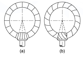
Figure1: Types of Bevel Gears: (a) Straight Bevel Gear (b) Spiral Bevel Gear
Terminology
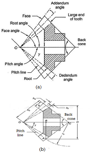
Figure 2 Terminology of Bevel Gear
A bevel gear is in the form of the frustum of a cone. The following terms are important in terminology of bevel gears:
(i) Pitch Cone Pitch cone is an imaginary cone, the surface of which contains the pitch lines of all teeth in the bevel gear.
(ii) Cone Centre The apex of the pitch cone is called the cone centre. It is denoted by O.
(iii) Cone Distance Cone distance is the length of the pitch-cone element. It is also called pitch-cone radius. It is denoted by A0 and it is given by

(iv) Pitch Angle The angle that the pitch line makes with the axis of the gear, is called the pitch angle. It is denoted by g. The pitch angle is also called centre angle.
(v) Addendum Angle It is the angle subtended by the addendum at the cone centre. It is denoted by a.
(vi) Dedendum Angle It is the angle subtended by the dedendum at the cone centre. It is denoted by d.
(vii) Face Angle It is the angle subtended by the face of the tooth at the cone centre.
Face angle = pitch angle + addendum angle = g + a
(viii) Root Angle It is the angle subtended by the root of the tooth at the cone centre.
Root angle = pitch angle – dedendum angle = g – d
(ix) Back Cone The back cone is an imaginary cone and its elements are perpendicular to the
Elements of the pitch cone.
(x) Back Cone Distance It is the length of the back cone element. It is also called back cone radius. It is denoted by rb.
Virtual number of teeth (z’) the number of teeth on the formative gear is called the virtual or the formative number of teeth denoted by z’. The formative number of teeth is given by,

Where, z= actual number of teeth
m= module at the large end of the tooth.
Force analysis bevel gears
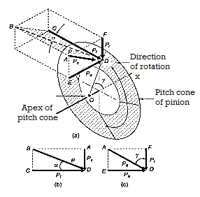
Figure 3 Components of tooth forces
In force analysis, it is assumed that the resultant tooth force between two meshing teeth of a pair of bevel gears is concentrated at the midpoint along the face width of the tooth. The resultant force P has following three components shown in figure.
Table 1 forces on bevel gear tooth
Force | Expression |
Tangential force (Pt) |  |
Radial force (Pr) |  |
Axial or thrust force (Pa ) |  |
Pt = tangential lor useful component (N)
Pr = radial component (N)
Pa = axial or thrust component (N)
In figure (a) from triangle BCD

Where,
Ps = separating component (N)
α = pressure angle (degrees)
Where,
T = torque transmitted by gears (N-mm)
rm = radius of the pinion at midpoint along the face width (mm), and given by expression

Example. A pair of bevel gears transmitting 7.5 kW at 300 rpm is shown in Figure. The pressure angle is 20°. Determine the components of the resultant gear tooth force.
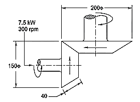
Solution Given kW = 7.5, np = 300 rpm, α = 20°, Dp =150 mm, Dg = 200 mm ,b = 40 mm


Or γ = 36.87˚


Beam Strength of Bevel Gear
In order to determine the beam strength of the tooth of a bevel gear, it is considered to be equivalent to a formative spur gear in a plane perpendicular to the tooth element. Consider an elemental section of the tooth at a distance x from the apex O and having a width dx. Applying the Lewis equation to a formative spur gear at a distance x from the apex,
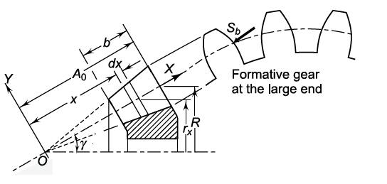
Figure 4 Beam Strength of the bevel gear tooth

δ(Sb) = beam strength of the elemental section (N)
mx = module of the section (mm)
bx = face width of elemental section (mm)
Y = Lewis form factor based on virtual number of teeth
From figure,

At elemental section

At the large end of the tooth

We get

And


Upon integration we get,

Assuming beam strength (Sb) as the tangential force at the large end of tooth,

Hence,

The face width of the bevel gear is limited to one-third of the cone distance. Therefore, the last term in the bracket will never be more than (1/27). Neglecting the last term,

Where,
Sb = beam strength of the tooth (N)
m = module at the large end of the tooth (mm)
b = face width (mm)
σb = permissible bending stress (Sut/3) (N/mm2)
Y = Lewis form factor based on formative number of teeth
A0= cone distance (mm)
 is the bevel factor.
Key Takeaways:
- The elements of the teeth of the spiral bevel gears are spiral curves which also converge into a common apex point.
- A bevel gear is in the form of the frustum of a cone.
- Face Angle It is the angle subtended by the face of the tooth at the cone centre
This information is valid for bevel gears which are used for power transmission in general industrial machines. The applicable ranges are:
Transverse module / m / 1.5 – 25mm
Pitch diameter / d0 / 1600mm or less (for straight bevel gears), 1000mm or less
(for spiral bevel gears)
Tangential speed / v / 25m/s or less
Rotational speed /n / 3600rpm or less
To apprehend the bevel equipment enamel geometry, one may first reveal the case of heterosexual bevel gears. If the producing rack used to gain the cylindrical equipment involutes is curved in a horizontal aircraft right into a round shape, it effects in a crown equipment which is used to derive the flank shape of bevel pinion and equipment.
For directly bevel gears the crown equipment or producing equipment may be positioned amid the pinion and equipment assembly. Its middle is positioned correctly on the intersection factor of the pinion and equipment shafts. As a intellectual put in force the crown equipment need to consist of a totally skinny fabric like aluminum foil. For all 3 factors it's miles to be in mesh at the same time.
A unmarried define of the producing equipment generates a equipment on its one floor and the mating member on its different floor. The define and lead is straight away which reasons a directly lead and an octoid define on the generated tooth. The octoid basically is the bevel equipment analog of an involute. The octoid affords stable ratio and makes the gears insensible to displacements vertical to the pitch line.
Virtual Number of Teeth
The teeth profiles of bevel equipment must be urbanized on a round aircraft. As a real growth of a round floor right into a aircraft isn't possible, an estimate needs to be made for which the digital wide variety of tooth is to be resolute. This problem is described as the wide variety of tooth which a spur equipment might have radius of that's equal to the again cone distance and having pitch of the bevel equipment.
The virtual number of teeth is given by
Tv = 2πRb/P
= T/cos Ψ
Where P is circular pitch and Ψ is pitch cone angle.
Force Analysis of Bevel Gear
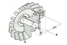
Fig 5: Components of tooth force
For pressure research of pair of mating bevel gear, it is unspecified that the entire pressure PR NR acts at the pitch factor on the centre of the enamel width.
The consequential but truly takes place somewhere among the midpoint and the again cease of enamel but the fault because of above speculation is marginal.
Here we've represented the forces Fn, FR, Fa, by PN via way of means of Pa and PR, stress perspective φ via way of means of αR nR and pitch perspective ϒ via way of means of Ψ correspondingly. The imply enamel pressure PR N Ris resolved in 3 similarly perpendicular components. They are tangential pressure Pt, radial pressure Pr Rand the axial pressure Pa.
The tangential force is considered as following
Pt = (2 Mt/d)
Where Mt = Transmitted torque = 60 x 10^6 (KW) / (2πN) (N-mm)
d = Pitch circle diameter (mm)
Radial force, Pr = Pt tan αn Cos Ψ
Axial force, Pa = Pt tan αn Sin Ψ
If the shaft angle is 900 then the following relation holds good
Pa = Pr
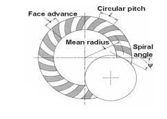
Fig 6: Illustration of spiral angle
The instances mentioned above are the instances of straight bevel equipment. Now we are able to communicate approximately spiral bevel equipment. In the recognised determine spiral attitude is proven through Ψ but we gave denoted it through β for our ease. A variety of forces appearing on spiral bevel equipment are given as following:
Tangential force, Pt = (2 Mt/d)
Radial force, Pr = Pt (tan αn cos Ψ –sinβ sin Ψ)/ cosβ
Where β is the mean spiral angle
Axial force, Pa = Pt (tan αn sin Ψ +sinβ cos Ψ)/ cosβ
Key takeaways:
- This information is valid for bevel gears which are used for power transmission in general industrial machines.
- To apprehend the bevel equipment enamel geometry, one may first reveal the case of heterosexual bevel gears.
- For all 3 factors it's miles to be in mesh at the same time.
- The octoid affords stable ratio and makes the gears insensible to displacements vertical to the pitch line.
Effective load on Gear Tooth
Tangential force on the bevel gear tooth is given in table, which depends upon the rated power and rated speed. But during the operation a dynamic load also acts on the gear tooth which can be considered in following two basis-
(i) Based on velocity factor this method of load estimation is used in preliminary stages of gear design. The effective load in this stage is given by

Where,
Cs = service factor
Cv = velocity factor, for helical gear velocity factor is given by following relation
The velocity factor for cut teeth is given by

The velocity factor for generated teeth is given by,

v= velocity in m/sec
(ii) Buckingham equation In the final stages of gear design, when gear dimensions are known, errors specified and the quality of gears determined, the dynamic load is calculated by equation derived by Earle Buckingham and given by following equation

Where Pd= incremental dynamic load, given by

v = pitch line velocity (m/s)
C = deformation factor (N/mm2)
e = sum of errors between two meshing teeth (mm)
b = face width of tooth (mm)
Pt = tangential force due to rated torque (N)
Deformation factor C is given by

Where,
k = constant depending upon the form of tooth
Ep = modulus of elasticity of pinion material (N/mm2 )
Eg = modulus of elasticity of gear material (N/mm2 )
Example. A pair of bevel gears, with 20°pressure angle, consists of a 20 teeth pinion meshing with a 30 teeth gear. The module is 4 mm, while the face width is 20 mm. The material for the pinion and gear is steel 50C4 (Sut = 750 N/mm2). The gear teeth are lapped and ground (Class-3) and the surface hardness is 400 BHN. The pinion rotates at 500 rpm and receives 2.5 kW power from the electric motor. The starting torque of the motor is 150% of the rated torque. Determine the factor of safety against bending failure and against pitting failure.
Solution Given kW = 2.5, np = 500 rpm, zp = 20, zg = 30, m = 4 mm, b = 20 mm, Sut = 750 N/mm2 , BHN = 400 starting torque = 150% (rated torque), machining grade = Class-3, α = 20º
Y=0.33715, C=11400 N/mm2
(I) Beam strength

Or 


(II) Wear strength


(III) Tangential force due to rated torque


(IV) Dynamic load by Buckingham’s equation
The error for Class-3 gear teeth with 4 mm module is 0.0125 mm. (from data sheet)


(V) Effective Load

(VI) Factor of safety
Against bending failure

Against pitting failure

Key Takeaways:
- Tangential force on the bevel gear tooth is given in table, which depends upon the rated power and rated speed.
- The effective load in this stage is given by

Worm gear drives are used to transmit power between two non-intersecting shafts, which are, in general, at right angles to each other. The worm gear drive consists of a worm and a worm wheel.
The worm is a threaded screw, while the worm wheel is a toothed gear. The teeth on the worm wheel envelope the threads on the worm and give line contact between mating parts.
Worm and worm gear terminology
A pair of worm gears is specified and designated as z1/z2/q/m:
Where,
z1 = number of starts on the worm
z2 = number of teeth on the worm wheel
q = diametral quotient
m = module (mm)
The diametral quotient is given by,

Where,
d1=pitch circle diameter of the worm
(i) Axial Pitch (px) The axial pitch of the worm is defined as the distance measured from a point on one thread to the corresponding point on the adjacent thread, measured along the axis of the worm.
(ii) Lead The lead (l) of the worm is defined as the distance that a point on the helical profile will move when the worm is rotated through one revolution.

(iii) Lead Angle (γ) The lead angle is defined as the angle between a tangent to the thread at the pitch diameter and a plane normal to the worm axis.

(iv) Helix Angle (ψ) The helix angle is defined as the angle between a tangent to the thread at the pitch diameter and the axis of the worm. The worm helix angle is the complement of the worm lead angle.

(v) Pressure Angle (α) The tooth pressure angle is measured in a plane containing the axis of the worm and it is equal to one-half of the thread angle.
Key Takeaways:
- The worm gear drive consists of a worm and a worm wheel.
- The lead angle is defined as the angle between a tangent to the thread at the pitch diameter and a plane normal to the worm axis.
- The worm helix angle is the complement of the worm lead angle.
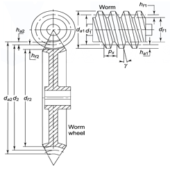
Figure 7. Dimension of Worm Gear
The basic dimensions of the worm and the worm wheel are shown in Fig. 4.1. For an involute helicoidal tooth form,


Where,
ha1 = addendum (mm)
hf1= dedendum (mm)
c = clearance (mm)
The outside and root diameters of the worm are expressed as follows:


Where
da1 = outside diameter of the worm (mm)
df1 = root diameter of the worm (mm)
The addendum and dedendum of the worm wheel at throat can be expressed as


Where,
ha2 = addendum at the throat (mm)
hf2 = dedendum in the median plane (mm)
The dimensions of the worm wheel are as follows:


Where,
da2 = throat diameter of the worm wheel (mm)
df2 = root diameter of the worm wheel (mm)
The effective face width (F) of the worm wheel is given by

The length of the root of the worm wheel teeth (lr) is given by

Example. A pair of worm gears is designated as,1/30/10/8
Calculate
(i) The dimensions of the worm; and
(ii) The dimensions of the worm wheel
Solution. Given, z1=1, z2=30, q=10, m=8mm
(i) The dimensions of the worm


Or 

(ii) The dimensions of the worm wheel


The analysis of three components of the resultant tooth force between the meshing teeth of Suffix 1 is used for the worm, whilesuffix 2 for the worm wheel. All the components of resultant force are shown in figure. Worm and worm wheel is based on the following assumptions:
(i) The worm is the driving element, while the worm wheel is the driven element.
(ii) The worm has right-handed threads.
(iii) The worm rotates in anti-clockwise directions as shown in Fig.
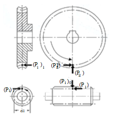
Figure 8. Forces on Tooth Force
The components of the resultant force acting on the worm are as follows:
(P1)t = tangential component on the worm (N)
(P1)a = axial component on the worm (N)
(P1)r = radial component on the worm (N)
The force acting on the worm wheel is the equal and opposite reaction of the force acting on the worm. From figure, it is observed that
(P2)t=(P1)a
(P2)a=(P1)t
(P2)r=(P1)r
The resultant force acting on the worm consists of two components
(i) Normal reaction between the meshing teeth and
(ii) Frictional force.
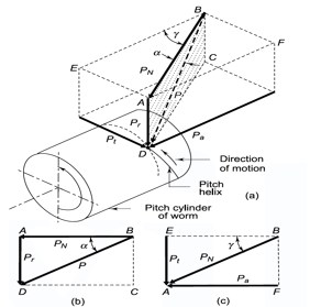
Figure 9. Components of Normal Reaction
The components of the normal reaction P acting on the worm are shown in Fig. Here, α is the normal pressure angle, while  is the lead angle. Note that the angle α is in the plane ABCD shaded by dots, while the angle g is in the top plane AEBF. Resolving the normal reaction P in the plane ABCD shown in Fig. 9(b).


Resolving the component PN in the plane AEBF shown in Fig. 9 (c).


From above relations


The frictional force is significant in worm gear drives, because there is sliding motion between the threads of the worm and the teeth of the worm wheel, as compared with the rolling motion between the teeth of the pinion and gear in other types of gears. The resultant frictional force is (μP) where μ is the coefficient of friction. The direction of the frictional force will be along the pitch helix and opposite to the direction of rotation, as shown in Fig. 10. There are two components of the frictional force:
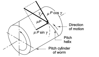
Figure 10. Components of Frictional force
(i) Component (μ P cos γ) in the tangential direction. The direction of this component is same as that of Pt.
(ii) Component (μ P sin γ) in the axial direction. The direction of this component is opposite to that of Pa.
Superimposing the components of normal reaction and frictional force, we have


Generally,


Example. A pair of worm and worm wheel is designated as 3/60/10/6. The worm is transmitting 5 kW power at 1440 rpm to the worm wheel. The coefficient of friction is 0.1and the normal pressure angle is 20°. Determine the components of the gear tooth force acting on the worm and the worm wheel.
Solution. Given kW = 5 n = 1440 rpm m = 0.1α= 20° z1 = 3 z2 = 60 teeth q = 10m = 6 mm
(i) Components of tooth force acting on worm


Or 


(ii) Components of tooth force acting on worm Wheel
(P2)t=(P1)a=2632.55 N
(P2)a=(P1)t=1105.24 N
(P2)r=(P1)r=1033.35 N
Key Takeaways:
- The worm is the driving element, while the worm wheel is the driven element.
- The force acting on the worm wheel is the equal and opposite reaction of the force acting on the worm.
- Note that the angle α is in the plane ABCD shaded by dots, while the angle g is in the top plane AEBF.
It has been observed that the coefficient of friction in worm gear drives depend upon the rubbing speed. The rubbing speed is the relative velocity between the worm and the wheel.
The pitch line velocity (V1) of the worm is given by,

Rubbing velocity Vs is given by,

Pitch line velocity of the worm wheel V2

The variation of the coefficient of friction with respect to rubbing velocity is shown in Fig.
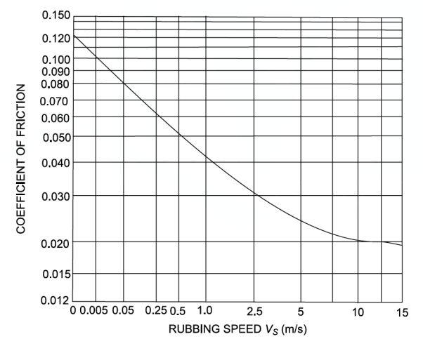
Figure 11. Coefficient of Friction of Worm Gears
The efficiency of the worm gear drive is given by,

For self-locking drive,

For overrunning/reversible/back-driving drive

Example. 1 kW power at 720 rpm is supplied to the worm shaft. The number of starts for threads of the worm is four with a 50 mm pitch–circle diameter. The worm wheel has 30 teeth with 5 mm module. The normal pressure angle is 20°. Calculate the efficiency of the worm gear drive and power lost in friction.
Solution. Given kW = 1, N = 720, rpm α = 20°, d1 = 50 mm, Z1 = 4, Z2 = 30 teeth, m = 5 mm.
Efficiency of worm gear drive
Using 


From figure, 

Power lost in friction

The selection of materials for the worm and the worm wheel is more limited than it is for other types of gears.
The threads of the worm are subjected to fluctuating stresses and the number of stress cycles is fairly large. Therefore, the surface endurance strength is an important criterion in the selection of the worm material.
The core of the worm should be kept ductile and tough to ensure maximum energy absorption.
The following varieties of steel are used for the worm:
Normalized carbon steels—40C8, 55C8
Case-hardened carbon steels—10C4, 14C6
Case-hardened alloy steels–16Ni80Cr60, 20Ni2Mo25
Nickel–chromium steels—13Ni3Cr80, 15Ni4Cr1
The worm wheel cannot be accurately generated in the hobbing process. The final profile and finish of the worm wheel teeth is the result of plastic deformation during the initial stages of service. Therefore, the worm wheel material should be soft and conformable. Phosphor-bronze, with a surface hardness of 90–120 BHN, is widely used for the worm wheel.
Key Takeaways:
- Therefore, the surface endurance strength is an important criterion in the selection of the worm material.
- Normalized carbon steels—40C8, 55C8
- Phosphor-bronze, with a surface hardness of 90–120 BHN, is widely used for the worm wheel.
The worm gears are usually designed according to national and international codes. There are two basic equations: beam strength and wear strength equations. The maximum permissible torque that the worm wheel can withstand without bending failure is given by the lower of the following two values:


Where,
Tt1, Tt2= permissible torque on the worm wheel (N-mm)
Xb1, Xb2 = speed factors for strength of worm and worm wheel
Sb1, Sb2 = bending stress factors of worm and worm wheel
m = module (mm)
lr = length of the root of worm wheel teeth (mm)
d2 = pitch circle diameter of worm wheel (mm)
γ = lead angle of the worm
The bending stress factor (Sb) for various materials is given in Table 2. The speed factor for strength (Xb) of worm gears is obtained from figure.
Table 2 Value of bending stress factor (Sb)
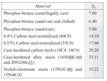
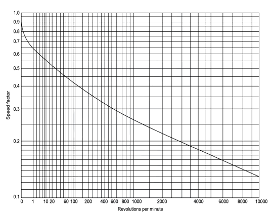
Figure 12. Speed factor for worm gears for strength (Xb)
Example. A pair of worm and worm wheel is designated as, 1/30/10/10. The input speed of the worm is 1200 rpm. The worm wheel is made of centrifugally cast, phosphor bronze and the worm is made of case-hardened carbon steel 14C6. Determine the power transmitting capacity based on the beam strength.
Solution. Given, n1 = 1200 rpm, z1 = 1, z2 = 30 teeth, q = 10, m = 10 mm.
Permissible torque on the worm wheel

Therefore 


Using, 

c = 0.2 m cos g = 0.2(10) cos (5.71) = 1.99 mm
da1 = m (q + 2) = 10 (10 + 2) = 120 mm

From Table, we get Sb1 = 28.2, and, Sb2 =7.0.
From Figure we get Xb1 = 0.25, and Xb2 = 0.48


The lower value of the torque on the worm wheel is 12 389 922 N-mm, hence it is the permissible value of the torque on worm wheel.
Power transmitting capacity based on beam strength

Wear ratings of worm gears
The maximum permissible torque that the worm wheel can withstand without pitting failure, is given by the lower of the following two values:


Where,
Tt3, Tt4= permissible torque on the worm wheel (N-mm)
Xc1, Xc2 = speed factors for the wear of worm and worm wheel
Sc1, Sc2 = surface stress factors of the worm and worm wheel
Yz= zone factor
The values of the surface stress factor (Sc) for the various materials are given in Table 3. The values of the worm gear zone factor are given in Table 4. The speed factors (Xc) for wear depend upon the rotational speed and the rubbing speed Vs.
Table 3 Surface stress factor (Sc)
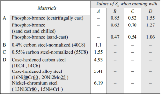
Table 4 Worm gear zone factor (Yz)

Example. A pair of worm and worm wheel is designated as, 1/30/10/10. The input speed of the worm is 1200 rpm. The worm wheel is made of centrifugally cast, phosphor bronze and the worm is made of case-hardened carbon steel 14C6. Determine the power transmitting capacity based on the beam strength.
Solution. Given, n1 = 1200 rpm, z1 = 1, z2 = 30 teeth, q = 10, m = 10 mm.
Permissible torque on the worm wheel

Therefore 


From table we get for z1 = 1 and q=10, Yz=1.143.
From table we get Sc1 = 4.93 and Sc2 = 1.55

From figure Xc1 = 0.112, and Xc2 = 0.26.


The lower value of the torque on the worm wheel is  N-mm, hence it is the permissible value of the torque on worm wheel.
Power transmitting capacity based on beam strength

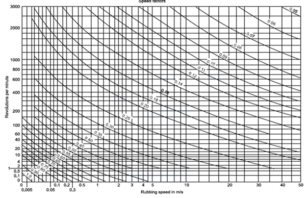
Figure 13. Speed factor Xc for the worm gear
Key Takeaways:
- There are two basic equations: beam strength and wear strength equations.
- Sb1, Sb2 = bending stress factors of worm and worm wheel
- The values of the worm gear zone factor are given in Table. The speed factors (Xc) for wear depend upon the rotational speed and the rubbing speed Vs
1443 - 93rd Congress (1973-1974): Foreign Assistance Act of 1973 | Congress.gov | Library of Congress.
The Act defines fashionable responsibilities on employers, employees, contractors, providers of products and materials to be used at work, men and women on top of things of labour premises, and people who control and preserve them, and men and women in fashionable.
The Act allows a large regime of law with the aid of using authorities ministers thru Statutory Instrument which has, with inside the years due to the fact 1974, generated an intensive device of particular provisions for numerous industries, disciplines and risks.
It hooked up a device of public supervision thru the advent of the Health and Safety Commission and Health and Safety Executive, due to the fact merged, and bestows huge enforcement powers, in the long run subsidized with the aid of using crook sanctions extending to limitless fines and imprisonment for up to 2 years. Further, the Act gives a vital interface with the regulation of the European Union on place of work fitness and safety.
Objectives:
- Securing the fitness, protection and welfare of individuals at work;
- Protecting individuals, apart from individuals at work, towards dangers to fitness or protection springing up out of or in reference to the sports of individuals at work;
- Controlling the preserving and use of explosive or extraordinarily flammable or in any other case risky substances, and commonly stopping the illegal acquisition, ownership and use of such substances.
- As at first enacted, there has been a fourth objective: Controlling the emission into the surroundings of noxious or offensive substances; however this provision changed into repealed while manipulate of emissions changed into added beneath Neath a uniform scheme of regulation with the aid of using the Environmental Protection Act 1990.
The Act lays down widespread ideas for the control of fitness and protection at work, allowing the advent of unique necessities thru policies enacted as Statutory Instruments or thru a code of practice. For example, the Control of Substances Hazardous to Health Regulations 2002 (COSHH), the Management of Health and Safety at Work Regulations 1999, the Personal Protective Equipment (PPE) at Work Regulations 1992 and the Health and Safety (First-Aid) Regulations 1981 are all Statutory Instruments that lay down exact necessities.
It became additionally the aim of the Act to rationalise the present complicated and burdened gadget of legislation (segment 1(2)). Since the accession of the United Kingdom to the European Union (EU) in 1972, a lot fitness and protection law has had to follow the regulation of the European Union and Statutory Instruments beneath Neath the Act had been enacted on the way to enforce EU directives.
In particular, the Act is the foremost manner of complying with Directive 89/391/EEC on fitness and protection at work. Further crucial adjustments to segment 6, obligations in admire of articles and materials used at work, had been made with the aid of using the Consumer Protection Act 1987 on the way to enforce the Product Liability Directive 85/374/EEC.
Key Takeaways:
- Further, the Act gives a vital interface with the regulation of the European Union on place of work fitness and safety.
- Health and Safety (First-Aid) Regulations 1981 are all Statutory Instruments that lay down exact necessities.
- In particular, the Act is the foremost manner of complying with Directive 89/391/EEC on fitness and protection at work.
The efficiency of a worm gear drive is low and then work done by friction is converted into heat. When the worm gears operate continuously, considerable amount of heat is generated. The rate of heat generated (Hg ) is given by,

Where,
Hg = rate of heat generation (W)
η = efficiency of worm gears (fraction)
KW = power transmitted by gears (kW)
The heat is dissipated through the lubricating oil to the housing wall and finally to the surrounding air. The rate of heat dissipated (Hd) by the housing walls to the surrounding air is given by,

Where,
Hd = the rate of heat dissipation (W)
k = overall heat transfer coefficient of housing walls (W/m2 °C)
t = temperature of the lubricating oil (°C)
t0 = temperature of the surrounding air (°C)
A = effective surface area of housing (m2)
Equating the heat generated and heat dissipated we get,

From the above equation we can find the resultant temperature and the power transmitting capacity of worm gear drive.
Key Takeaways:
- When the worm gears operate continuously, considerable amount of heat is generated.
- The heat is dissipated through the lubricating oil to the housing wall and finally to the surrounding air.
References:
1. Design Data - P.S.G. College of Technology, Coimbatore.
2. Vehicle Powertrain Systems by Behrooz Mashadi, David Crolla. A John Wiley & Sons, Ltd
3. Automobiles–Power trains and Automobiles–Dynamics by Crolla, David, A John Wiley & Sons, Ltd
4. Automotive Engineering Powertrain, Chassis System and Vehicle Body by David A Crolla, Elsevier B H New York, London, Oxford.
5. Lack P.H. And O. Eugene Adams, Machine Design, McGraw Hill Book Co. Inc.