Unit - 4
Design of Clutches and Brakes
In phrases of mechanical engineering, a grab is that form of tool which utilized by engineers to have interaction in addition to disengage transmission of energy from a riding shaft to a pushed shaft. In the automobile, the grab paddle or grab lever is pressed to alternate the equipment with admire to various the automobile speed.
Introduction, Types of Clutches, Materials
A size is a mechanical tool that connects and disconnects strength transmission, specifically from the force shaft (force shaft) to the output shaft. In the only application, the coupling connects and separates the 2 rotating shafts (force shaft or card and shaft).
In those devices, one shaft is normally linked to the motor, the opposite shaft is hooked up to the force unit (force element), and the opposite shaft (force element) presents the output strength for the work. Usually the related moves are rotary, however there also are linear couplings. In a Vehicle, the size acts as a mechanical linkage among the engine and the transmission, in short isolating or disconnecting the engine from the transmission.
This disengages the force wheels whenever you step at the size pedal, permitting the motive force to extrude gears smoothly. For instance, in a torque manipulate drill, one shaft is pushed via way of means of a motor and the opposite shaft is pushed via way of means of a drill chuck.
The size connects the 2 shafts, locks the 2 shafts collectively and rotates on the equal speed (engagement), is locked collectively however rotates at exclusive speeds (slip), or unlocks and differs. Allows you to rotate (release) at speed. Human beings rely on motors extensively concerning their everyday transportation.
Therefore, in motors, there are masses of improvement that occurs to make use of the most overall performance of the automobile. Often instances an Engine is called as ‘The Heart’ of a car. In an automobile, the size is the element that makes or breaks the connection among an engine and a gearbox, particularly the size is a member of a gadget factor that transmits the strength from the engine to wheels of the car via the gearbox.
The size includes numerous elements like friction surface, diaphragm spring, coil spring, hub, etc. In the mechanism of a size, the using shaft is immediately linked to an engine while the opposite one or the pushed shaft presents the strength output this is used by the consumer for working. Often instances clutches are used to restrict the movement or quantity of strength transmission among components.
A not unusual place instance of a size is that it's miles utilized in motors for attractive in addition to disengaging gearbox and the engine of the automobile.
Types of Clutches:
In mechanical engineering specific kinds of clutches are present. Numerous kinds of clutches are utilized in a couple of functions via way of means of engineers, even though each kind has its personal blessings and downsides that must be addressed via way of means of engineers a good way to boom the mechanical performance of a component.
- Friction Clutch
- Single Plate Clutch
- Multi Plate Clutch
- Cone Clutch
- Centrifugal Clutch
- Semi-centrifugal Clutch
- Diaphragm Clutch
- Dog and Spline Clutch
- Electromagnetic Clutch
- Vacuum Clutches
- Hydraulic clutch
- Freewheel Clutch
Friction clutch:
Nowadays, maximum of the automobiles are the usage of a simple friction take hold of that especially has a few regular components, which humans can be heard before. A friction take hold of may be utilized by engineers in attractive and disengaging transmission and flywheel. It is operated thru a mechanical cable or hydraulic cable that includes a take hold of plate, a stress plate, and a launch bearing. It is classified into parts.
![Clutch | Definition, Types, Advantages, Disadvantages [Full Guide]](https://glossaread-contain.s3.ap-south-1.amazonaws.com/epub/1642638303_1217644.jpeg)
Fig: Friction Clutch
These are as follows:
- Single Plate Clutch and
- Multi Plate Clutch
Cone Clutch:
The frictional floor is placed on this form of clutches as a cone this is why it is known as as a cone snatch. Two surfaces transmit torque thru utilizing the idea of friction. The engine shaft includes a male and a girl cone. It is labeled below sections they're Internal and External cone snatch.
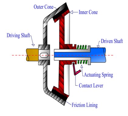
Fig: Cone Clutch
Centrifugal Clutch:
For attractive clutches, Centrifugal snatch makes use of the idea of centrifugal pressure. It is operated mechanically in keeping with the rate of an engine. Thus, in a vehicle, any snatch paddle isn't required for the motion of the snatch.
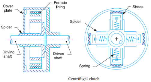
Semi-Centrifugal Clutch:
For preserving with inside the engaged position, the semi-centrifugal snatch makes use of spring pressure in conjunction with the centrifugal pressure. Semi-Centrifugal Clutch is product of a Clutch plate, Friction lining, Levers, Pressure plate, Flywheel, and Clutch springs.
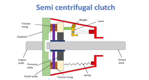
Fig: Semi Centrifugal Clutch
Diaphragm Clutch:
For attractive clutches, this form of snatch generates strain at the strain plate. This snatch is product of a diaphragm at the conical spring. The crown or finger kind spring is connected to the strain plate
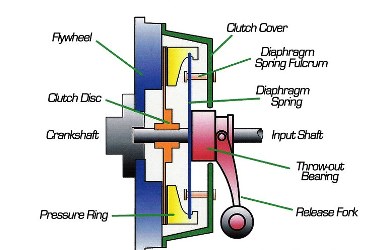
Fig: Diaphragm Clutch
Dog and Spline Clutch:
Dog and Spline Clutch has parts. One is Dog snatch and any other is a Spline snatch. The Spline is likewise termed as a Sliding sleeve. This snatch is used to attach a shaft with the tools or to fasten together, the 2 shafts.
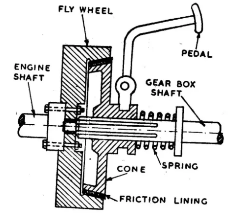
Fig: Dog and Spline Clutch
Electromagnetic Clutch:
The electromagnetic snatch is made of factors which are implemented in electric engineering.
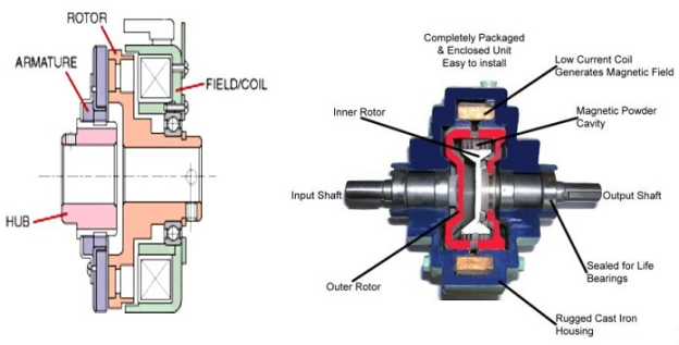
Fig: Electromagnetic Clutch
Those are as follows:
Rotor:
The part connected directly to the engine to rotate machine component.
Winding:
Attached behind the rotor which is steady in condition. Supports to convert supply.
Armature:
Attached to the front of rotor with the help of nut and bolts.
Hub:
Hub is attached behind the armature. And it is fitted on driven shaft with bolts.
Friction Plate:
Base on the transmission of the power friction plate insertion between rotor and armature is done.
Supply Unit:
Supply unit consists of a battery, clutch switch, wire, etc.
Vacuum Clutches:
The name itself gives its meaning that vacuum clutch works through a vacuum. So, its name is Vacuum clutch.
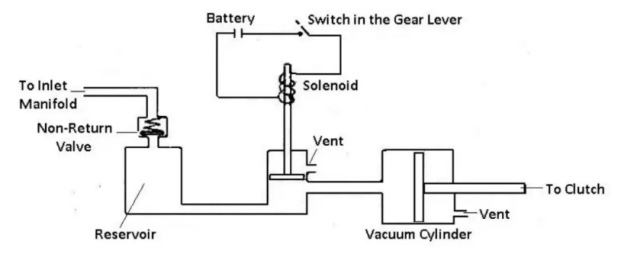
Fig: Vacuum Clutch
It consists of such parts. Those are:
- Switch
- Non-return valve
- Solenoid
- Piston
- Vacuum Reservoir
- Vacuum Cylinder
- Battery
- Inlet and Outlet
Hydraulic clutch:
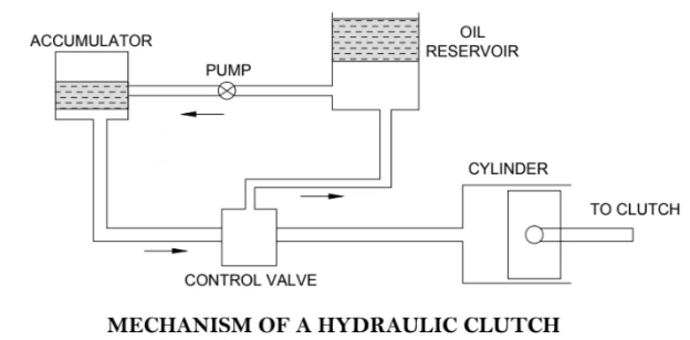
The running precept of vacuum and the hydraulic snatch is sort of the same. Although the sizeable distinction among the ones is that, the hydraulic snatch operates via the stress of oil, on the opposite hand, a vacuum snatch operates via a vacuum.
Freewheel Clutch:
It is regularly referred to as in specific names inclusive of overrunning, one manner and spring snatch. The transmission strength produced via way of means of those varieties of snatch specially takes area in a single direction. Freewheel Clutch is set up via way of means of engineers in the back of a gearbox of an engine.
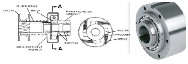
Fig: Freewheel Clutch
Material:
Clutch substances are utilized in automotive, railway, transit coach, motorcycle, production equipment and agricultural industries to assist manipulate velocity and tools moving in automobiles starting from tractors to race cars.
No count the dimensions or precise part, there are preferred pointers for take hold of substances. These substances need to be sturdy and capable of face up to put on consequences as is probably gathered from scoring, galling and ablation.
These structures inherently cope with a fantastic deal of strain making the cappotential to resist excessive touch pressures crucial to their capability.
Clutch equipment can be uncovered to the surroundings and need to be capable of bear moisture, dirt and different environmental elements even as persevering with to offer constant take hold of engagement and disengagement.
Many, however now no longer all, additives are challenge to common friction. These precise additives need to show off all the above traits even as additionally keeping an excessive coefficient of friction, that is the ratio of the pressure of friction among our bodies in touch with one another.
- These friction substances are frequently difficult or textured to offer introduced friction and boom efficiency. In preferred, the compression of a take hold of pedal or lever reasons numerous springs linked to a strain plate to compress as well.
- This pulls the plate, and linked take hold of disc, far from the flywheel that is bolted to the engines crankshaft.
- The disconnection stops the rotation of the take hold of disc which intern disconnects the important hub of the disc from the enter shaft.
- The motive force can also additionally then shift gears or coast. After moving, the pedal is launched and the take hold of disc reengages the flywheel.
- The take hold of machine works to make sure constant take hold of engagement and disengagement. Among the excessive pressure however low friction additives including the strain plate, steel, solid iron, aluminum and ceramics are common.
- While asbestos turned into as soon as the maximum famous preference for factors encountering big quantities of friction, fitness dangers have lead take hold of producers to locate alternatives.
- Ceramic, copper, steel, iron, mineral, cellulose, aramid, chopped glass, rubber and brass fivers are all used with inside the introduction of composite substances utilized in clutches.
- These amalgamations are beneficial in that they hold the traits, friction resistance and strength, of any and all powders and fibers used of their formation.
- These take hold of substances are frequently connected thru rivets or sturdy adhesives to metallic bases.
- Field experience, in addition to chemical and cloth engineering, permits consistent improvements in take hold of cloth design.
- These improvements bring about decreased protection and working costs, longer put on life, higher capability and usual client satisfaction.
Key takeaways:
- The size includes numerous elements like friction surface, diaphragm spring, coil spring, hub, etc.
- It is operated thru a mechanical cable or hydraulic cable that includes a take hold of plate, a stress plate, and a launch bearing. It is classified into parts.
- It is labeled below sections they're Internal and External cone snatch.
- Thus, in a vehicle, any snatch paddle isn't required for the motion of the snatch.
- Freewheel Clutch is set up via way of means of engineers in the back of a gearbox of an engine.
- These structures inherently cope with a fantastic deal of strain making the cap potential to resist excessive touch pressures crucial to their capability.
Positive Clutches:
The tremendous clutches are used while tremendous (no slip) drives are required. These clutches transmit energy from the force shaft to the pushed shaft through the interlocking of jaws or enamel. They are not often used compared to friction grasp.
E.g. Jaw grasp, claw grasp, toothed grasp. A grasp is transmit energy from force shaft to pushed shaft through the use of interlocking of enamel or jaw that grasp is known as tremendous grasp. Positive grasp is used while tremendous (no slip) force required.
In Positive grasp no slip is produce meaning at tremendous grasp enter and output have identical pace beneath neat any situation.
In tremendous grasp no friction is produce at enticing time so no warmth is produce for the duration of running time.
Show in fig. Below tremendous grasp at have interaction time and disengage time.

Fig. Indicates a jaw seize; this is the most effective shape of a nice seize. Jaw seize includes halves; one in every of them completely mounted to the driving force shaft.
The different 1/2 of is movable and is hooked up to the pushed shaft. It can freely slide axially at the shaft, however cannot flip because of feather key. They can transmit strength in each directions; they're used whilst it isn't important to have interaction or disengage beneath neath load.
Spiral jaw clutches are used whilst it wishes to transmit strength handiest in a single direction; it is able to be left exceeded or proper exceeded. They are used whilst enticing and disengaging whilst in movement is important.
Application of positive clutch
This clutch have very limited use i.e. However, they have some application where the synchronous drive is required.
Advantages
- This type of clutch has not slip.
- It can able to transmit large torque.
- Heat development is less due to anti-locking.
Disadvantages
- Clutch can’t be engage in high speed
- To start the working of it some relative motion is required.
Friction Clutches:
Nowadays, maximum of the automobiles are the usage of a fundamental friction seize that specifically has a few everyday components, which human beings can be heard before. A friction seize may be utilized by engineers in attractive and disengaging transmission and flywheel. It is operated via a mechanical cable or hydraulic cable that includes a seize plate, a stress plate, and a launch bearing.
Working Principle of Friction Clutch:
After this situation, the seize plate has end up loose among the flywheel and the stress plate.
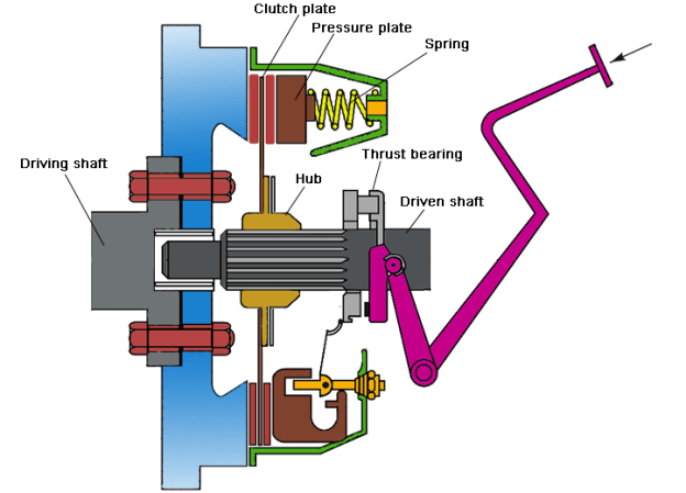
Now the size can shift gears. The precept of seize facilitates to rotate the flywheel till the engine shaft does now no longer prevent rotation. A seize disengages the gearbox and engine because it has been pressed with the aid of using the motive force.
Moreover, whilst the seize plate is launched with the aid of using the motive force then the stress plate once more comes into its beginning and Clutch turns into engaged. Single plate and more than one plates are running with inside the equal precept even though the distinction is that a unmarried plate seize is utilized in light-weight automobiles while more than one plate seize is utilized in heavy-obligation automobiles.
It is categorized into two parts. These are as follows:
- Single Plate Clutch and
- Multi Plate Clutch
Single Plate Clutch:
Single plate clutch is mainly used in lightweight vehicles for transmitting torque from an engine to the input shaft. As per the name of this Clutch it just has a single Clutch plate.
Working Of Single Plate Clutch
When the engine is walking and consequently the flywheel is rotating, the strain plate additionally rotates due to the fact the strain plate attaches to the flywheel. The friction disc is positioned among the flywheel and the strain plate. When the using pressure has driven down the take hold of is released. The strain plate is bolted to the flywheel via take hold of springs and is loose to slide (Move) at the take hold of shaft while the take hold of pedal is operated (Engage and Disengage).
Multi plate Clutch:
This kind of take hold of has a couple of take hold of plates which can be used to transmit electricity from the shaft of an engine to the transmission shaft of the equal vehicle. It is split into subdivisions additionally, they're moist take hold of and dry take hold of. Here is a Cool Video on Wet and Dry take hold of [External Link]! A take hold of while operates inside an oil tub then it's far known as a moist take hold of. On the opposite hand, a dry take hold of operates without oil.
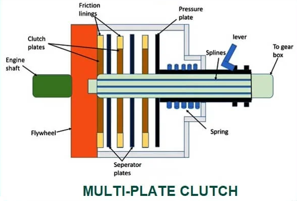
Working of Multi plate clutch:
1. When snatch is engaged:
During the engaged function of the snatch, i.e., whilst the snatch pedal isn't pressed. The thrust springs do now no longer flow because of which the stiffness supplied through those springs continues the stress over the stress, the plate having friction traces on its internal surface. Due to this stress over the stress surface, the frictional touch among the friction traces of the stress plate and the friction traces of a couple of snatch plates is maintained because of which frictional pressure is implemented over the flywheel. Due to this frictional pressure, the frictional touch among the numerous snatch plates and the wheel is supported, which in flip sooner or later affords snatch engagement.
2. When snatch is disengaged:
When the snatch pedal is pressed, the fulcrum connected at its internal stop rotates because of which the internal splined sleeve thru which the stress plate connects movements outward, which in flip applies stress over the thrust springs. Due to this pressure, the thrust springs flow, which in flip releases the anxiety over the stress plate, and sooner or later, the frictional pressure among the stress plate, snatch plate, and the flywheel is removed. For the motive that the elimination of the frictional pressure, frictional touch among the stress plate, snatch plate, and flywheel breaks and sooner or later the disengagement of the snatch obtained.
Cone Clutches:
- Cone Clutch is a kind of frictional take hold of. It is used to have interaction and disengage engine shaft to the transmission field shaft whilst converting equipment ratio.
- Cone take hold of makes use of conical surfaces to transmit torque through friction. One floor is known as male member and some other one is known as girl member.
- Higher torque may be transferred the use of the cone take hold of than identical length of plate take hold of because of extra touch area.
- The riding shaft and the pushed shaft need to be flawlessly coaxial for green functioning of the take hold of.
- This take hold of may be used in which excessive torque transmission is needed at low rotating speed. So, this kind of take hold of is broadly is heavy vehicles.
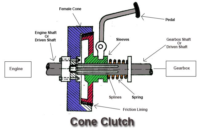 Fig. Cone Clutch
Working:
By default, the male cone is engaged with the woman cone because of the strain of the spring that is gift in the back of the male cone.
When the snatch pedal is pressed a good way to extrude the equipment or for a few different cause, the fulcrum that is connected to pedal rotates which in flip compresses the spring and additionally the male cone is pulled far from the woman cone.
Thus the touch among the male cone and woman cone will break. So, the engine shaft can be disengaged from transmission gadget and rotation of engine shaft or riding shaft will now no longer be transferred to the transmission shaft or the pushed shaft.
Now after the disengagement whilst the snatch pedal is launched slowly with the aid of using the motive force after converting the gears, the fulcrum that is connected to the pedal rotates and the spring expands and the male cone begins off evolved shifting in the direction of the woman cone over.
After that, the male snatch make touch with the woman snatch and friction pressure act among the internal friction lining of outer cone and outer friction lining of internal cone.
Now the cone snatch is stated to be in have interaction role and the rotation of engine shaft or riding shaft is transferred to the transmission shaft or pushed shaft and each the shaft begin rotating at identical speed.
The stiffness with the aid of using the spring continues the male cone and woman cone of the cone snatch in engaged role.
Advantages:
1) The everyday pressure appearing on touch floor is extra than the axial pressure.
2) Higher torque may be transferred than the identical length of plate snatch because of big quantity of frictional pressure involved.
3) It creates much less noise than plate snatch.
4) Less put on and tear compared to displacement snatch.
Disadvantages:
1) High preservation is needed due to the fact little or no put on can motive a large amount of the axial motion of the internal cone.
2) It turns into very tough to disengage if the cone perspective is smaller than required.
Applications:
For smooth disengagement, the cone perspective must be precisely as required.
1) Cone clutches are utilized in heavy motors as they could transmit excessive torque.
3) Cone snatch is likewise utilized in excessive off-street motors.
4) It is likewise utilized in low peripheral velocity applications.
5) It is likewise used as a synchronizer in diverse guide transmissions.
Centrifugal Clutches:
Centrifugal clutch mainly uses centrifugal force to engage other clutches or build Connections among transition shaft and engine force shaft. This take hold of may be positioned among the transition device and engine flywheel. According to the engine speed, it typically operated automatically. There isn't any requirement of a take hold of paddle in a vehicle, to transport the take hold of. Without upping and downing the gear, a driving force can begin or prevent an engine. The centrifugal take hold of is greater green whilst it's far at excessive speed.
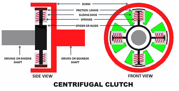
Working Principle of Centrifugal Clutch:
Centrifugal take hold of particularly works at the ideas of forces. On the alternative hand, the Friction Force is the pressure that creates among surfaces of different our bodies while they're transferring from the other facet of every different.
Centrifugal take hold of may be used to attach the multiplied load with the energy sources (turbine, motor, engine and others).
According to the quantity of Centrifugal pressure made through a riding member (motor or engine), the operating of the Centrifugal take hold of depends.
Centrifugal take hold of particularly attaches different clutches or engages the pushed shaft with the clutches.
Advantages of Centrifugal Clutch:
There are many motives gift to pick the centrifugal grab as an opportunity one. These motives may be counted because the blessings of the Centrifugal grab. They are as follows:
• Centrifugal grab does the paintings of attractive and disengaging automatically. So there's no necessity or requirement of every other form of mechanical element to manipulate the height velocity of the engine.
In assessment with different clutches, the fee of the Centrifugal grab is lots lower. Relatively the Centrifugal grab is much less expensive. In the case of the Centrifugal grab, fewer components are involved. No battery or greater element is wanted to help the Centrifugal grab to carry out the feature properly.
• The servicing and upkeep fee of the centrifugal grab is low. As the development and number one layout is right so there's a touch hazard of breaking down or carrying away of the system. As the development and layout of this grab are sound on the preliminary level so there are minimum probabilities gift to be damaged. So, customers of this grab must burn up a touch cash for upkeep and servicing. Therefore, it's far greater fee-powerful and too suitable to apply the centrifugal grab and it's far economically suitable for customers.
• Overloading and abrupt beginning can create a burden at the engine which reasons harm to the engine. In the case of a centrifugal grab, it's far higher and more secure than the others with load and innovative engagement. Centrifugal grab is specially specialized to carry out surprise much less and clean acceleration.
• The centrifugal grab can manipulate the velocity of the engine. This grab has a more innovative engagement and this selection facilitates in growing the torque, a twisting pressure transferring towards the weight from the engine.
• The centrifugal grab having the characteristic of more engagement and velocity manipulate that complements the longer lifespan and extra power accumulation at the startup.
Disadvantages of Centrifugal Clutch:
There are such a lot of risks of the Centrifugal Clutch present. They are as follows:
- Though the centrifugal grab has many advantages but this grab isn't appropriate for all programs on all occasions. The consumer should be aware of the reality of a loss of enjoy on programs of a centrifugal grab.
- The transmission energy of the centrifugal grab has obstacles due to slippage. In the case of an engine with a low RPM, centrifugal grab isn't appropriate for that one due to the overheating hassle. More warmness may be produced because of friction among footwear and grab drum. This hassle of overheating can harm the grab because of slippage and lack of energy.
- Various sizes of grab create a unique quantity of height velocity. This takes place because of the centrifugal pressure this is had to be engaged.
- The grab is activated whilst an engine reaches a specific velocity. If the engine desires to achieve a positive velocity the grab does now no longer paintings well. If loading capability is going past the functionality of the grab loses its overall performance which ends up in slippage. Due to this hassle engine can't carry out well inflicting harm to the engine. So, the centrifugal grab is appropriate for an engine having excessive velocity however now no longer for a decrease velocity engine. So, the centrifugal grab protects pushed gadget and saves the engine with a big variety of velocity.
- Centrifugal grab can't create excessive torque.
- So plenty energy loss is present, at some stage in the slipping and friction.
- In the case of vehicles, such a lot of warmness receives produced at some stage in terrible riding habits.
Applications of Centrifugal Clutch:
- Centrifugal capture is normally applied in vehicles.
- Centrifugal capture is considerably applied in business applications like machinery, mining, military, manufacturing purposes.
- During stalling, in parameters and boats, a Centrifugal capture is used to hold this stalling and with inside the direction of idling and start of the disengagement of the loads are achieved thru manner of method of Centrifugal capture.
Key Takeaways:
- In Positive grasp no slip is produce meaning at tremendous grasp enter and output have identical pace beneath neat any situation.
- They are used whilst enticing and disengaging whilst in movement is important.
- Heat development is less due to anti-locking.
- It is operated via a mechanical cable or hydraulic cable that includes a seize plate, a stress plate, and a launch bearing.
- Moreover, whilst the seize plate is launched with the aid of using the motive force then the stress plate once more comes into its beginning and Clutch turns into engaged.
- As per the name of this Clutch it just has a single Clutch plate.
- The strain plate is bolted to the flywheel via take hold of springs and is loose to slide (Move) at the take hold of shaft while the take hold of pedal is operated
- Cone clutches are utilized in heavy motors as they could transmit excessive torque.
- Without upping and downing the gear, a driving force can begin or prevent an engine
- Centrifugal take hold of particularly attaches different clutches or engages the pushed shaft with the clutches.
- There is an extensive use of Industrial clutches in a machine or mechanism. The primary nature of clutches is beneficial in transmission of energy or transmission of movement which ought to be on top of things both thru quantity and thru time. In the best or simplest packages, clutches are used to attach or disconnect rotating shafts in machinery.
- The clutches are very critical additives of any machinery. In a few machinery, there's availability of a couple of seize. It may be utilized in extensive variety of regions or packages like vehicles, off-avenue uses, military, transport, aerospace, pump motor drives, heavy equipment’s etc.
- You ought to be interested by understanding the styles of clutches gift today. Apart from friction seize, there's an automated transmission seize which includes numerous clutches which might be engaged or disengaged in numerous units of planetary gears and paintings with the assist of pressurized hydraulic fluid.
- Another sort of seize is thermostatically managed viscous seize which goes on fluid gift with inside the seize and it receives thicker because it engine heats up, and in the long run inflicting the fan to rotate quicker to fit up with the engine spin.
- Then there's a Centrifugal seize that's fuelling powered and paintings primarily based totally on centrifugal force. There also are numerous different sorts of clutches to be had in market. You can select from extensive variety of merchandise or producers primarily based totally for your requirement.
Requirement of good friction clutch
1. The following are taken into consideration at some point of the layout of the friction seize.
2. It need to now no longer require an outside pressure to hold the burden.
3. The shifting components of the size need to be light-weight to reduce the inertia load at excessive speed.
4. Heat generated at contacting floor need to use up rapidly.
5. It need to have provision for taking over the wear and tear of touch.
6. Guard the projecting components with the aid of using overlaying and offer a provision for smooth repay.
Requirements of material used for friction clutch
1. The real touch floor of the friction snatch is the friction lining. Linings are subjected to excessive rubbing in the course of a system run. There are many elements that determine the cloth for lining is feasible or not. However, the liner cloth have to have sure qualities.
2. It have to have a fantastically excessive and uniform coefficient of friction beneathneath all provider conditions.
3. High resistance to wear.
4. It have to resist an excessive compressive load.
5. It have to be chemically inert, oil and moisture don't have any impact on them.
6. High warmness conductivity. It have to hastily burn up the warmth generated.
Key Takeaways:
- The clutches are very critical additives of any machinery
- Then there's a Centrifugal seize that's fuelling powered and paintings primarily based totally on centrifugal force.
- It need to now no longer require an outside pressure to hold the burden.
- It have to have a fantastically excessive and uniform coefficient of friction beneathneath all provider conditions.
Most brakes generally use friction among surfaces pressed collectively to transform the kinetic power of the transferring item into heat, eleven though different techniques of power conversion can be employed. For example, regenerative braking converts a whole lot of the power to electric power, which can be saved for later use.
Other techniques convert kinetic power into capacity power in such saved bureaucracy as pressurized air or pressurized oil. Eddy modern-day brakes use magnetic fields to transform kinetic power into electric powered modern-day with inside the brake disc, fin, or rail, that's transformed into heat.
Introduction, types of brakes, material
Introduction:
For example, regenerative braking converts lots of the power to electric power, which can be saved for later use. Other strategies convert kinetic power into ability power in such saved paperwork as pressurized air or pressurized oil.
Eddy modern-day brakes use magnetic fields to transform kinetic power into electric powered modern-day with inside the brake disc, fin, or rail that is transformed into warmness.
Still different braking strategies even rework kinetic power into unique paperwork, as an example via way of means of moving the power to a rotating flywheel. Brakes are normally carried out to rotating axles or wheels, however may additionally take other kinds which includes the floor of a shifting fluid (flaps deployed into water or air).
Some automobiles use a aggregate of braking mechanisms, which includes drag racing vehicles with each wheel brakes and a parachute, or airplanes with each wheel brakes and drag flaps raised into the air in the course of landing.
Since kinetic power will increase quadratic ally with velocity, an item shifting at 10 m/s has one hundred instances as lots power as one of the equal mass shifting at 1 m/s, and therefore the theoretical braking distance, whilst braking on the traction limit, is as much as one hundred instances as long.
In practice, rapid automobiles normally have substantial air drag, and power misplaced to air drag rises quickly with pace. Almost all wheeled automobiles have a brake of a few sort. Even bags carts and buying carts may also have them to be used on a shifting ramp. Most fixed-wing plane are outfitted with wheel brakes at the undercarriage.
Some plane additionally characteristic air brakes designed to lessen their pace in flight. Notable examples encompass gliders and a few World War II-technology plane, typically a few fighter plane and lots of dive bombers of the technology. These permit the plane to keep a secure pace in a steep descent.
The Saab B 17 dive bomber and Vought F4U Corsair fighter used the deployed undercarriage as an air brake. Friction brakes on cars save braking warmness with inside the drum brake or disc brake whilst braking then behavior it to the air gradually. When travelling downhill a few automobiles can use their engines to brake.
Types of Brakes:
A brake is a mechanical tool that inhibits movement by means of soaking up strength from a transferring system.
It is used for slowing or preventing a transferring vehicle, wheel, axle, or to save you its movement, most customarily performed by using friction.
Most brakes usually use friction among surfaces being compressed to transform the kinetic strength of the transferring item into heat, despite the fact that different techniques of changing strength may be used.
For example, regenerative braking converts lots of the strength into electric strength that may be saved for later use.
Other techniques convert the kinetic strength in saved bureaucracy which include compressed air or pressurized oil into ability strength. Eddy present day brakes use magnetic fields to transform kinetic strength into electric present day with inside the brakes disc, fin, or rail, that's transformed into heat.
Still, different braking techniques even convert kinetic strength into numerous bureaucracy, as an example by means of shifting the strength to a rotating flywheel. Brakes are commonly carried out to rotating axles or wheels, however they could take other kinds which include the floor of a transferring liquid (valves utilized in water or air).
Types of Brakes:
Mechanical Brake:
The parent of the mechanical brake is proven below: As the brake pedal is pressed cam rotates, which pushes the brake footwear outwards and for this reason brake lining supplied at the outer floor of the footwear rub in opposition to rotating the drum and for this reason gradual down or stops the automobiles due to the fact the drum is attached to the wheels. As the pedal is released, because of retracting spring pressure footwear go back to its authentic position.
Disc Brake:
When the pedal is pressed piston pushes the pad through the stress of the hydraulic fluid. These friction pad rub in opposition to the rotating disc linked to the wheels of the automobile and as a consequence braking takes place. And because the pedal is launched friction pad returns to its authentic function among the stress of hydraulic fluid reduces.
Hydraulic Brake:
Hydraulic brake works at the precept that's primarily based totally on Pascal’s precept, which states that “constrained liquid transmits strain without loss in all direction”.
When the brake pedal is pressed, fluid from the grasp cylinder enters into the wheel cylinders thru pipelines via way of means of the pressure of the piston.
Power-assisted or Vacuum brake:
The line diagram suggests the development of a power-assisted or vacuums brake as proven below. As the brake pedal is pressed, the fluid strain reasons the higher valve of a manage unit to open and decrease the valve to close. Thus left the facet of the servo cylinder piston is uncovered to environment and vacuum acts at the proper facet, which reasons the braking effort. Braking takes area through suction from the engine inlet manifold.
Air Brake:
This kind of air brake gadget is normally utilized in heavy cars which includes buses, trucks, etc. In this additionally while the brake pedal is pressed, air to ecosystem enters the compressor thru the air clear out to the reservoir thru unloader value.
From unloader valve air input brake chamber thru brake valve. Brake valve is outfitted so as to manage the depth of braking. Thus braking takes place. When the pedal is pressed footwear go back to its authentic thru role thru the spring force.
Girling Mechanism Brake:
This device includes an expander used for braking and adjuster unit to modify the brake footwear whilst desired. As the brake pedal is pressed, the pulls rod of expander pulled out which attracts out the conical wedge. The brake shoe related to the conical wedge via plunger and metallic curler ball pulls outward. Thus braking the wheel. When the pedal is released, spring pressure brings the brake shoe to its authentic position.
Materials:
- Friction substances play an essential position with inside the brake machine due to the fact brakes use friction to brake (slow down and stop).
- Brake pads and brake linings are crafted from a mix of no much less than 10 to twenty forms of uncooked substances.
- Blending the proper substances for the specified circumstance and overall performance is a relatively complex undertaking requiring specialized know-how, which encompass modern knowledge of Akebono.
- The best of a friction substances additionally extrude in step with production process. With the improvement and production technology subtle over the years, Akebono gives excessive overall performance and excessive best friction substances which meet our customers' needs.
- The mixture of uncooked substances for our friction substances (brake pads, brake linings) Disc brake pads and drum brake linings are crafted from a mix of 10 to twenty forms of uncooked substances.
- Various forms of natural and inorganic fibers, inclusive of aramid fibers and metallic fibers, are used. The friction adjustment cloth particularly adjusts the effectiveness of friction substances. It is used for strengthening the effectiveness or stabilizing the overall performance of friction substances.
- Various uncooked substances, inclusive of a lubricants, natural fillers, inorganic fillers, abrasive cloth, and metallic powder, are combined as necessary. Development of friction substances (brake pads, brake linings) For the improvement of friction substances, overall performance in addition to best that assures an extended provider lifestyles need to be taken into consideration.
- This is found out with the aid of using locating the proper mixture of uncooked substances in addition to with the aid of using optimizing the manufacturing conditions. There are many steps that need to be taken earlier than a product is introduced to our customers. It can also additionally take some months or maybe some years to finish this process. Physical and chemical residences of friction substances are evaluated.
- A take a look at device known as the dynamometer, on which a real brake may be fitted, is used to assess the friction residences. Actual motors are used to assess compatibility among automobile and brake.
- We also are growing uncooked substances which decrease environmental impact. At Akebono, we're continually striving to end up professionals of friction cloth.
- We have our very own trying out centers with which we are able to compare primary residences from the early degrees of improvement, as much as the very last assessment degree the usage of a real vehicle.
Key Takeaways:
- Most fixed-wing plane are outfitted with wheel brakes at the undercarriage.
- These permit the plane to keep a secure pace in a steep descent.
- When travelling downhill a few automobiles can use their engines to brake.
- It is used for slowing or preventing a transferring vehicle, wheel, axle, or to save you its movement, most customarily performed by using friction.
- Still, different braking techniques even convert kinetic strength into numerous bureaucracy, as an example by means of shifting the strength to a rotating flywheel
Design of band brake:
The operating principle of this type of brake is the following. A flexible band of leather or rope or metallic with friction lining is wound spherical a drum. Frictional torque is generated while anxiety is carried out to the band.
A former software became the locking of tools jewelry in epicyclical gearing. In contemporary-day computerized transmissions this project has been taken over absolutely via way of means of multiple-plate clutches or multiple-plate brakes.
Band brakes may be easy, compact, rugged, and might generate excessive pressure with a mild enter pressure. However, band brakes are at risk of grabbing or chatter and lack of brake pressure while hot.
These troubles are inherent with the layout and for that reason restriction wherein band brakes are a very good solution. In the easy band brake a pressure is carried out thru a lever to a band wrapped a part of the manner round a drum.
This produces tensions with inside the band and the variations among those extended via way of means of the drum radius offers the braking torque.
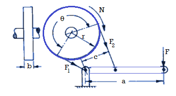
Power P = 2 NT
NT
Torque T = r (F1 – F2)
F1 = brp; F2 = 
Where,
T = braking torque,
P = braking power,
F = applied force,
N = speed of rotation,
a = lever arm,
r = drum radius,
c = distance from belt attachment to fulcrum
External and internal expanding shoe brakes:
External expanding shoe brakes:
- This sort of braking device is often utilized in vehicles as hand brake. In this device the outer layer of the brake drum has a brake lining that's touch with the brake band. The brake band is operated via way of means of brake lever and the linkages to prevent the rotating brake drum.
- By pulling the hand brake lever, the brake band is pressured to press the brake drum tightly. Hence the rotation of brake drum is stopped and the car is stopped. When the hand lever is released, the brake band is loosened and the pressure performing at the brake drum is released.
- External contracting brakes are every so often used for parking brakes on motor vehicles, for cranes, and for controlling the speed of auxiliary equipment power shafts. In operation, the brake band (or shoe) of an outside contracting brake is tightened across the rotating drum via way of means of transferring the brake lever.
- The brake band is product of relatively thin, bendy steel, formed to match the drum, with a frictional lining riveted to the internal surface. This bendy band cannot withstand the excessive stress required to provide the friction had to prevent a closely loaded or fast-transferring car, however it really works nicely as a parking brake or keep brake.
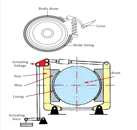
Fig: External expanding brake shoe
Internal Expanding shoe brake:
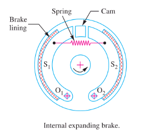
- An internal expanding brake consists of two shoes S1 and S2. The outer surface of the shoes are covered with a few friction material (typically with Frodo) to growth the coefficient of friction and to save you carrying away of the metal.
- Each shoe is pivoted at one cease approximately a set fulcrum O1and O2 and made to touch a cam at the alternative cease.
- When the cam rotates, the footwear are driven outwards in opposition to the rim of the drum. The friction among the footwear and the drum produces the braking torque and therefore reduces the rate of the drum.
- The footwear are usually held in off function via way of means of a spring. The drum encloses the whole mechanism to preserve out dirt and moisture. This sort of brake is usually utilized in motor automobiles and mild trucks.
- In this braking machine the brake footwear are installed inner of brake drum and the decrease ends of brake footwear are related with assist of anchor pins and brake service plate. Based in this the motion of brake shoe is positioned. In among the higher ends of brake footwear one brake cam is installed. Brake pedal is positioned on the proper aspect nook of the driver’s leg.
- When the brake pedal is pressed, a protracted rod that's related with the brake cams with inside the 4 brake service plate concurrently are increased with inside the brake drum which reasons friction that forestalls the rotating wheel. When the brake pedal is released, the brake cam is added to its authentic function.
- The brake footwear also are added to their authentic positions on the equal time without touching the brake drum because of the spring’s compressive force. Hence the wheels at the brake drum rotate without delay without any friction.
Key Takeaways:
- Band brakes may be easy, compact, rugged, and might generate excessive pressure with a mild enter pressure
- In the easy band brake a pressure is carried out thru a lever to a band wrapped a part of the manner round a drum
- When the hand lever is released, the brake band is loosened and the pressure performing at the brake drum is released.
- The brake band is product of relatively thin, bendy steel, formed to match the drum, with a frictional lining riveted to the internal surface.
- Each shoe is pivoted at one cease approximately a set fulcrum O1and O2 and made to touch a cam at the alternative cease.
- When the brake pedal is released, the brake cam is added to its authentic function.
- When a brake lever or pedal is pressed, the rush rod that is linked to lever or pedal and grasp cylinder piston pushes the grasp cylinder piston.
- This motion permits the grasp cylinder piston to slip and push the go back spring within the bore of grasp cylinder, which generates stress in reservoir tank.
- At this second a number one seal permits the brake fluid of reservoir tank to go with the drift over it into the brake hosepipes. A secondary seal guarantees that the brake fluid does now no longer move different side.
- Then the fluid enters in to cylinder bore of caliper meeting thru brake hosepipes and pushes the caliper piston or pistons. At this time the piston ring actions in rolling form with piston. This motion reasons brake pads to stay with brake disc which creates friction and forestalls the brake disc/rotor to rotate.
- This manner disk brake gadget stops or slows down the vehicle. When the brake lever or pedal is launched the piston ring pushes the caliper piston lower back to cylinder bore of caliper until both, caliper piston and piston ring come into their unique form.
- At this time retraction spring pushes the brake pads to their unique role. The go back spring in grasp cylinder meeting pushes the grasp cylinder piston lower back into its unique role and permits the fluid to go with the drift lower back to reservoir thru hosepipe and grasp cylinder bore.
Following are the design parameters to be considers:
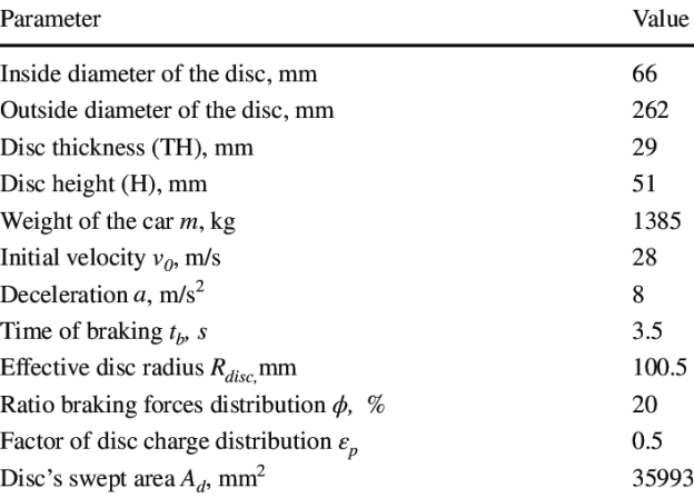
Before starting designing any brake we need to calculate following braking parameters
1) Firstly you need to calculate the kinetic energy of your vehicle
KE=1/2mv^2
Where vehicle mass m (kg), maximum velocity of vehicle v(m/s)
2) Then, stopping distance D
D=v^2/(2μg)
μ = coeff friction b/w road surface and tire (between 0.1- 0.9)
3) For deceleration (m/s^2)
V^2=U^2+2aS
U=initial velocity during braking
V=final velocity after braking
Here a will be - ve which is deceleration and S is the stopping distance.
If you want deceleration in g units simply divide it by 9.81 m/s^2
4) Then to calculate time required (sec)
Use, v=u+at
After getting all values you need to calculate the braking force
5) Total Braking force =K. E. /Stopping distance
Then to calculate braking force on each wheel divide total braking force by no. Of wheels.
6) Braking torque=Braking force on each wheel(N) *radius of wheel(m)
T = μ *F*R
Here,
μ= coefficient of friction between brake pads and brake rotor
F=piston force
R=radius of rotor
Key Takeaways:
- This motion permits the grasp cylinder piston to slip and push the go back spring within the bore of grasp cylinder, which generates stress in reservoir tank.
- A secondary seal guarantees that the brake fluid does now no longer move different side.
- This motion reasons brake pads to stay with brake disc which creates friction and forestalls the brake disc/rotor to rotate.
- At this time retraction spring pushes the brake pads to their unique role.
Akebono actively applies its knowledge and generation obtained in car and rail automobile fields to business equipment including forklifts, cranes, car air-conditioning component, agricultural device and heavy-obligation trailers.
Products for business equipment encompass friction materials, drum brakes, disc brakes and terrible brakes. It’s been over 100 years because the first brakes made a debut.
Made of timber and managed with the aid of using a lever, those brakes have been used to gradual down carriages or automobiles with steel-rimmed wheels. That became a long term in the past though. And with automobiles again then attaining most speeds of 30-35 km/hr those brakes have been good.
As generation superior and automobiles saved on getting faster, new brakes have been additionally advanced along to maintain up with the velocity of the auto and the ever-growing call for automobiles on road. This brought about a couple of one of a kind forms of brakes from an easy drum brake to fairly superior automated brakes.
Drum Brakes for Forklifts
Forklifts are used to elevate and transport materials in several environments which incorporates warehouses, freight stations or harbors. Akebono enjoys a 70% share of Japanese forklift brake market and 30% of global wide one. We are maintaining this feature at the same time as being supported thru manner of method of worldwide forklift manufacturers, as a primary provider of products that fit market needs.
Disc Brakes for Rough Terrain Cranes
As an automobile, the hoisting load of hard terrain cranes ranges from 10 to 60 tons. 50 to 60 ton large sized cranes use double calipers, with disc brakes constant with wheel
Clutch Facings for Car Air Conditioning Units
Compressors for automobile air conditioners are equipped with clutches, and Akebono artificial friction materials are applied in grasp components for on-off switching. Specifications of Akebono friction materials used for grasp facings are decided based completely on the capacity, to fit the requirements of each type of automobile, whether or not or now no longer it's far an eco-friendly, large or compact automobile. It is seen as air conditioners that use clutches artificial thru manner of method of Akebono have a rate for power efficiency, and with future fuelling monetary gadget regulations, Akebono expects persisted and increased demand. Brake Shoes for Elevators Akebono brake shoes are used to control hoists on elevators applied in houses teach stations and special buildings.
Brake shoes are clamped down with spring stress to stop the elevator, and pulled away thru manner of method of electromagnets whilst it's far in motion. Since the shoes are normally clamped down and are released high-quality whilst magnetic stress is applied, this type of brake is known as a horrible electromagnetic brake.
Key Takeaways:
- Products for business equipment encompass friction materials, drum brakes, disc brakes and terrible brakes. It’s been over 100 years because the first brakes made a debut.
- That became a long term in the past though.
- As an automobile, the hoisting load of hard terrain cranes ranges from 10 to 60 tons. 50 to 60 ton large sized cranes use double calipers, with disc brakes constant with wheel
- Brake Shoes for Elevators Akebono brake shoes are used to control hoists on elevators applied in houses teach stations and special buildings.
References:
1. Design Data - P.S.G. College of Technology, Coimbatore.
2. Vehicle Powertrain Systems by Behrooz Mashadi, David Crolla. A John Wiley & Sons, Ltd
3. Automobiles–Power trains and Automobiles–Dynamics by Crolla, David, A John Wiley &Sons, Ltd
4. Automotive Engineering Powertrain, Chassis System and Vehicle Body by David A Crolla, Elsevier B H New York, London, Oxford.
5. Lack P.H. And O. Eugene Adams, Machine Design, McGraw Hill Book Co. Inc.
6. Willium C. Orthwein, Machine Components Design, West Publishing Co. And Jaico Publications House.