Unit - 5
Design of M/C tool Gear Box
Machine Tool Gear Box:
A business gearbox is an enclosed device that transmits mechanical power to an output device. Gearboxes can adjust their speed, torque, and different attributes to transform the power right into a useable format. Gearboxes are utilized in plenty of devices, for a extensive variety of purposes. These machines can gradual the fee of rotation to growth torque and speed. The following will give an explanation for a number of the exclusive varieties of business gearboxes and the way they're normally used.
Advantages of machine tool gear box:
Force + Dynamic
High slicing charges for tender substances and excessive slicing forces for tough substances are required. These can reached thru the software of a switchable tools, wherein the excessive torques of the force motor (I = 1:1) are retained, however moreover accelerated the force toque of the motor thru the conversion (e.g. I = 4, 00) and the torque is decreased approximately the identical factor.
Flexible
The slicing capability is therefore consistent and is to be had throughout a huge torque variety. Only thru a tools this adaptability is accessible low-priced. Direct arbor extension (INLINE + TSC) these gears are installed at once on the arbor, no belts are required.
Torque and output
Depending at the motor adjustment variety with consistent output you could attain adjustment stages of consistent output as much as 1:20 at the primary arbour with the gears. Therefore on the only hand excessive torques bring about the decrease variety of velocity and however excessive speeds, with which you could take advantage of the slicing capability of current tools.
An equipment field for system device have to own the subsequent requirements: -
- Transmit preferred power
- Simple production in admire of overall variety of shafts, gears, clutches, bearing and manage machine components.
- Ease of wearing out preventive preservation and to make the modifications in bearing and clutches etc. through looking after smooth access.
Gear field can be constructed both into the spindle head (head stock), or be designed as a separate unit. Gear containers designed as a separate unit incorporated with spindle head offers an extra compact spindle power and additionally smooth to assemble.
However, in those, vibrations from the equipment field can be transmitted to the spindle equipment containers and additionally warmness produced with inside the equipment field may also warmness the spindle head.
In the case of equipment containers with a divided power, the equipment field and spindle head (head stock) are designed as separate gadgets and the equipment field is connected to the spindle head via some sorts of transmission.
In those equipment containers, the warmth produced with inside the equipment field through friction losses and vibrations aren't transmitted to the spindle head.
Helical gearbox
This system is used for an extensive variety of business applications, however generally in heavy-responsibility operations.
It is beneficial in crushers, extruders, coolers, and conveyors that are all low-electricity applications. The helical gearbox is specific in that its miles constant at an attitude which, while in movement, allows extra tooth to engage with inside the equal direction. This gives steady touch for a given length of time.
Extruder helical gearboxes are used while torsion stiffness desires to be maximized and for low-noise applications.
Extrusion gearboxes are used with inside the plastics enterprise and in machines that require excessive mechanical electricity.
Coaxial helical inline
The coaxial helical gearbox is good for heavy-responsibility applications. Coaxial helical in lines are stated for his or her great and efficiency. These are synthetic with an excessive diploma of specification, which permits you to maximize load and transmission ratios.
Bevel helical gearbox
The vital function of this sort of gearbox is a curved set of tooth positioned at the cone-formed floor near the rim of the unit. The bevel helical gearbox is used to offer rotary motions among non-parallel shafts. These are generally utilized in quarries, with inside the mining enterprise, and in conveyors.
Skew bevel helical gearbox
The skew bevel helical gearbox is first rate for its inflexible and monolithic structure, which makes it usable in heavy hundreds and different applications. These business gearboxes provide mechanical blessings as soon as they may be installed on the suitable motor shaft output. These are fantastically customizable primarily based totally at the wide variety of tooth and gears. Therefore, you may normally discover one appropriate in your desires.
Worm discount gearboxes
Worm discount gearboxes are used to pressure heavy responsibility operations. Worm gearboxes are used while there may be a want for elevated velocity discount among non-intersecting crossed axis shafts. This sort of business gearbox makes use of a Trojan horse wheel that has a big diameter. The Trojan horse, or screw, meshes with the tooth at the peripheral vicinity of the gearbox. The rotating movement of the Trojan horse reasons the wheel to transport in addition because of the screw-like movement. Most of those business gearboxes are utilized in heavy industries along with fertilizers, chemicals, and minerals.
Planetary gearbox
The planetary gearbox is good for its endurance, accuracy, and awesome capability and is first rate for its precision applications. This sort of gearbox growth the lifespan of your system and optimizes performance. Planetary gearboxes are available both a strong sort of hole layout or with quite a few mounting alternatives such as a flange, shaft, or foot.
Basic considerations in design of drives and its applications
The format interest for an energy is essential element in advance than manufacturing the gear energy.
The first step with inside the format of gear energy is the selection of a proper shape of gear for a required application.
The factors which may be considered for locating out the shape of gear are, fashionable layout of shaft. Tempo reduction. Strength to be transmitted. Input tempo. Cost.
Design Consideration For A Gear Drive Is As Follows:
1. The energy transmission ought to be most even as thinking about layout of equipment force.
2. Central distance among enter and output equipment is widely known on the time of layout.
3. Speed of the riding shaft and velocity of the pushed shaft is thinking about even as the layout of the equipment force.
4. At the time of layout of the equipment force the rate ratio of the entire and output equipment force ought to be taken into consideration.
5. The variety of tooth on pushed equipment and variety of tooth on riding equipment is taken into consideration even as designing of equipment force.
6. The dimensions of the entire and output equipment force inclusive of diameter (D) is taken into consideration.
7. The fabric choice for equipment force is important. And equipment force fabric having excessive corrosion resistance and put on resistance.
8. While thinking about layout for an equipment force the reliability of an equipment ought to be excessive even as working.
9. While designing of the equipment force the meshing among enter and output is ought to be easy and equipment force having quiet operation.
10. To thinking about designing parameter for equipment force the general price of the equipment force ought to be less.
11. The performance of equipment force is ought to be excessive even as thinking about designing parameter.
Advantages of Gear Drive:
1. Gear power is effective power and the rate of equipment power stays constant.
2. The center distance among the shafts is exceedingly small that outcomes in a compact constructions.
3. Gear power can transmit very massive electricity that electricity is past the variety of belt power and chain drives.
4. Gear power can transmit the movement at very low pace that aren't viable with the belt drives.
5. The performance of an equipment power may be very excessive. The performance of the spur equipment is 99%.
6. The converting pace ratio extensive variety is viable in equipment power.
7. Gear power required small area examine to belt power.
8. The accuracy of the paintings is excessive in equipment power.
Disadvantages of Gear Drive:
1. Gear power is high-priced as compared to belt power.
2. The upkeep value of tools power is extra examine belt power.
3. The tools power required right lubrications.
4. The production of a tools power is complex and or required professional workers.
5. Manufacturing value of tools power is extra. 6. The tools power required right alignment among the shafts.
Applications of gear drives:
- Internal or Ring Gears.
- They are much like spur gears, despite the fact that their enamel aren't floor at the outside, however at the internal of a wheel or rimmed ring.
- A pinion drives the internal gears and continues the path of angular velocity.
- Planetary Gears.
- Also referred to as epicycles gears, it's far a tools educate wherein a crucial tools has one or numerous outside gears round it.
- They are generally used for car transmissions.
- Rack and Pinion.
- Used in lathes to transport the longitudinal carriage, they do now no longer have a transmission ratio, however a period ratio.
- In this case, it's far known as the gap among axis, because the rack falls in the class of gears of limitless diameter.
General Applications Of Gears
Gears of various type, size and material are widely used in several machines and systems requiring positive and stepped drive. The major applications are:
- Speed gear box, feed gear box and some other kinematic units of machine tools
- Speed drives in textile, jute and similar machineries
- Gear boxes of automobiles
- Speed and / or feed drives of several metal forming machines
- Machineries for mining, tea processing etc.
- Large and heavy duty gear boxes used in cement industries, sugar industries, cranes, conveyors etc.
- Precision equipments, clocks and watches
- Industrial robots and toys.
Key Takeaways:
- Gear containers designed as a separate unit incorporated with spindle head offers an extra compact spindle power and additionally smooth to assemble.
- These are generally utilized in quarries, with inside the mining enterprise, and in conveyors.
- Planetary gearboxes are available both a strong sort of hole layout or with quite a few mounting alternatives such as a flange, shaft, or foot.
- Speed of the riding shaft and velocity of the pushed shaft is thinking about even as the layout of the equipment force.
- The dimensions of the entire and output equipment force inclusive of diameter (D) is taken into consideration.
Determination of variable speed range:
Nearly all of the VFDs in North America perform under this nominal frequency threshold. Yet a developing range of high-overall performance gear motor structures will gain from a extra competitive manipulate technique that cranks VFD running frequencies as much as 80, 90, or maybe one hundred twenty Hz. Under the proper circumstances, running a VFD at those higher-than-regular frequencies can beautify gear motor overall performance appreciably with inside the following ways:
- Increasing balance through lowering inertia mismatch
- Widening to be had velocity range
- Enabling the usage of smaller cars
- Reaping those benefits, however, calls for a few more layout attention.
When you power cars above 60 Hz, equipment ratio and to be had torque change. And those modifications want to be reconciled with the burden torques. What follows are strategies for pushing gear motors past 60 Hz, together with justifications for why doing so is a superb idea. You will even learn the way to interrupt the 60 Hz barrier appropriately and effectively. Finally, we’ll stroll thru a not unusual place instance on the way to display you the way to pick the right gear motor for an extensive velocity range.
Breaking the 60 Hz Barrier
Described in phrases of the motor’s magnetizing flux, the steady torque area represents the motor’s steady flux area, even as the steady horsepower area corresponds to the motor’s area weakened area.
60Hz also can be called the motor’s area weakening point.
From 0 to 60 Hz: Torque is steady.
And it conforms to the torque formula.
Torque (lb-in) = 63,025 * HP / Speed (RPM)
Voltage-to-frequency ratio is steady, too.
For example: 230 V/30 Hz equals 460 V/60 Hz Many engineers count on that the inverter and gear motor have to be designed round this 60Hz threshold. And gear motor providers do make it smooth to layout round this nominal frequency, considering the fact that maximum of the catalog and specification records are given for 60 Hz.
However, with a cautiously designed pressure gadget and accurate ratio, you may push the running frequency envelope above 60 Hz the use of both of demonstrated manipulate methods: area weakening or supercharging. Either approach gives the subsequent benefits, which range relying at the application.
- The calculation of the motor performance for a variable-pace centrifugal pump may be complex and calls for first the willpower of the pump pace, performance, and brake horsepower (BHP) required with the aid of using the pump at diverse factors at the water gadget's go with the drift head curve or with inside the gadget head place.
- Some pumping structures have simply one pump at the same time as others may have as many as 5 or six pumps.
- To simplify this assessment, we are able to keep in mind unmarried pump operation only. Figure eleven describes a water gadget with a uniform gadget head curve at the same time as describes a gadget with a gadget head place.
- This way that diverse water masses at the gadget are lively at exceptional times. Loads some distance from the pumping set up can be lively at one time at the same time as water masses close to the pump can be lively at different times.
- The above pump overall performance necessities might be decided with the aid of using use of the Affinity Laws for variable torque machines including centrifugal enthusiasts and pumps. The easy gadget head curve of might be used for this calculation of the motor performance as diverse factors at the curve.
Graphical Representation of Speed:
Speed – Time Graphs
We know that the speed at a certain time is the magnitude of the velocity at that time. So we can follow equations of motion to draw speed time graphs.
Case 1: Speed-time graphs with constant speed (zero acceleration)
When the speed is constant, the speed time graph, with Y-axis denoting speed and X-axis denoting time, will be like:
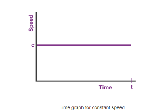
As clean from the graph, the velocity is regular (c) at some stage in the time interval. No remember how a lot the time changes, the velocity could be c at each instant. Example: If the acceleration of a particle is zero (0), and velocity is regular say five m/s at t =0, then it's going to stay regular at some stage in the time.
Case 2: Speed-time graphs with constant acceleration
When acceleration is constant the initial speed of particle is zero, the speed of the particle is increases linearly.
v = u + at
Since u = 0
v = at
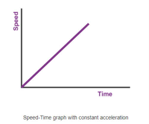
As proven with inside the figure, the velocity of the particle will boom linearly with recognize to time. The slope of the graph will deliver the significance of acceleration.
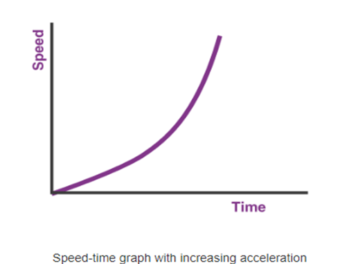
Case 3: Speed-time graphs with increasing acceleration
When acceleration increases with time, the speed graph will be showing curve nature as shown.
v = u + at
Since u = 0
v= at
Since acceleration is a function of time, speed time graph will be a curve.
Example
If the acceleration of a particle is a characteristic of time and preliminary pace is zero, the pace-time graph could be a curve. The slope of pace-time graph at any instant (at a positive time) will deliver the value of acceleration at that time.
Case three changed into simply the case of growing acceleration. There could be a distinct graph whilst the acceleration is lowering with time.
Structure Diagram:
A shape diagram is a conceptual modeling device used to file the exceptional systems that make up a machine which includes a database or an application. It suggests the hierarchy or shape of the exceptional additives or modules of the machine and suggests how they join and engage with every other.
A shape diagram is a conceptual modeling device used to report the extraordinary systems that make up a device including a database or an application.
It indicates the hierarchy or shape of the extraordinary additives or modules of the device and indicates how they join and engage with every different. It is a device used to manual builders to make sure that everyone elements of the device paintings as meant when it comes to all of the different elements.
A shape diagram is a improvement device utilized in modeling the extraordinary elements of a device, from the evaluate on how the character elements engage to create the whole, to modeling the info of the smallest elements themselves including the extraordinary items and instructions being utilized in programming the device. A shape diagram visualizes how a device works from the preliminary input, to processing and, finally, to the preferred output.
It is in particular beneficial in figuring out all the interfaces concerned among the extraordinary elements and facilitates builders agree on how every element need to be related primarily based totally at the fashions being proven at the shape diagram.
There are diverse styles of shape diagrams, which includes the following:
- Data shape diagram
- A conceptual statistics version used to report the entities in a database, their relationships, in addition to the restrictions related to them Composite shape diagram
- A form of static shape diagram that indicates the inner shape of a category and its collaborations with different instructions and items
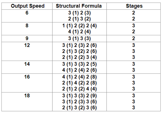
Let as assume 'n' velocity must be acquired from an unmarried enter, it isn't always feasible to mesh 'n' pair of gears in shafts to get the specified velocity. The most range of velocity that may be acquired from shafts is three. Hence it’s vital to apply intermediate shafts among the enter shaft and output shaft. The structural components enables to reach the range of tiers and required gears to acquire the preferred speeds. The following desk suggests the output range of speeds, the structural components and tiers required.
A Function Structure Diagrams (FSD) is a graphical example of the capabilities a product performs on its inputs and outputs.
Most importantly they may help destroy down a complicated format hassle into conceivable chunks. Solutions for each chew can be decided and then an engineering concept assembled from a hard and fast of solutions for each chew. Remember FSD’s vicinity the emphasis on what have to be finished in preference to how.
Key Takeaways:
- Finally, we’ll stroll thru a not unusual place instance on the way to display you the way to pick the right gear motor for an extensive velocity range.
- Either approach gives the subsequent benefits, which range relying at the application.
- Some pumping structures have simply one pump at the same time as others may have as many as 5 or six pumps.
- We know that the speed at a certain time is the magnitude of the velocity at that time. So we can follow equations of motion to draw speed time graphs.
- If the acceleration of a particle is zero (0), and velocity is regular say five m/s at t =0, then it's going to stay regular at some stage in the time.
In different words, the ray diagram is a graphical illustration of the structural formula, as proven in figure.
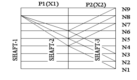
This is the graphical illustration of power arrangement & this offers the following information:
• No. Of stages
• No. Of speeds in every stage
• Values of transmission ratio
Principles to be followed to obtain Optimum Design:
To avoid excessively large diagram of beam & to limit the pitch line velocity of gear,
- In optics a ray is an idealized geometrical version of mild, acquired with the aid of using selecting a curve this is perpendicular to the wave fronts of the real mild, and that factors with inside the course of strength flow.
- Rays are used to version the propagation of mild via an optical device, with the aid of using dividing the actual mild discipline up into discrete rays that may be computationally propagated via the device with the aid of using the strategies of ray tracing.
- This permits even very complicated optical structures to be analyzed mathematically or simulated with the aid of using computer.
- Ray tracing makes use of approximate answers to Maxwell's equations which are legitimate so long as the mild waves propagate via and round items whose dimensions are tons more than the mild's wavelength.
- Ray optics or geometrical optics does now no longer describe phenomena consisting of diffraction, which require wave optics theory. Some wave phenomena consisting of interference may be modeled in constrained instances with the aid of using including section to the ray version.
1. No. Of gears on the last shaft must be minimum.
2. No. Of gears on any shaft should not be more than 3.
3. It is preferable to have  in every stage except first stage.
4. The transmission ratio 
5. The ratio 
6. Never keep the ratio 
Symbolically this condition is represented by
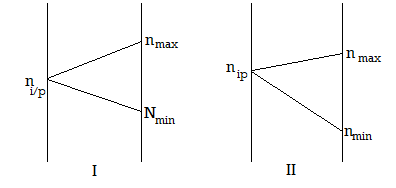
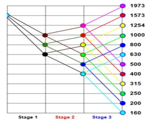
It offers the subsequent records at the drive:
The quantity of stages (a level is a fixed of tools trains organized on consecutive shafts)
The quantity of speeds in every level.
The overall quantity of speeds to be had on the spindle.
Procedure
In this diagram, shafts are proven through vertical equidistant and parallel traces.
Transmission engaged at precise speeds of the riding and pushed shafts are proven at the diagram through rays connecting the factors at the shaft traces representing these speeds.
Figure indicates the ray diagram for a nine velocity tools box, having the structural formula, z = 3 (1). 3 (3)
Since there are 4shafts, draw four vertical equidistant traces to symbolize shafts.
Since there are 12 spindle speeds, draw 12 horizontal equidistant traces.
From the structural formula, its miles clean that there are stages. In the 0.33 level, i.e., in 2 (6), 2 represents the wide variety of speeds to be had in that level and (6) represents the steps or periods among those speeds.
Locate the primary factor A on the bottom velocity i.e., at a hundred and sixty r.p.m. At the ultimate shaft. After 6 steps above, find the second one factor B at 630 r.p.m. These are the 2 output speeds.
Locate the enter velocity at any factor at the previous shaft (i.e., shaft 2), assembly the ratio requirements. We find, the enter velocity four hundred r.p.m. At factor C satisfies the ratio requirements. In the second one level, there are speeds. Lowest is at C, that's already positioned. Now find factor D at the third shaft, above factor C, in a 3 step interval. For those output speeds within side the 2nd level, the entire ought to be from shaft 2. We find, the enter velocity 630 r.p.m.
In the primary level, there speeds. Lowest velocity is at E, that's already positioned. Now find factors F and G at the shaft 2, above factor E, in a unmarried step interval.
Input velocity may be positioned everywhere on shaft 1 assembly the ratio requirements. But in this problem, given that, enter velocity is at 1600 r.p.m.
In level 2, we discover enter velocity at E offers output speeds at C and D. Similarly, enter speeds at F and G, ought to provide output speeds. This may be performed via way of means of drawing traces parallel to EC and ED, from factors F and G, as proven in figure
Now for level 3, to get the output speeds to all of the enter speeds in shaft 3, draw traces parallel to CA and CB. Thus we've positioned all of the entire and the output speeds. The finished ray diagram is proven in figure
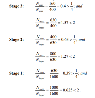
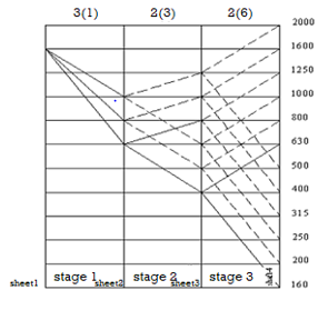
Ratio requirements are satisfied.
Selection of optical Ray Diagram:
BASIC RULES FOR OPTIMUM GEAR BOX DESIGN
The basic rules to be followed while designing the gear boxes are as follows:
1. The transmission ratio (i) in a gear box is limited by
 refer the figure
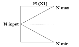
In other words,


2. For stable operation, the speed ratio at any stage should not be greater than 8. In other words, 
3. In all stages except in the first stage, Nmax Ninput Nmin
4. The sum of teeth of mating gears in a given stage must be the same for same module in a sliding gear set.
5. The minimum number of teeth on smallest gear in drives should be greater than or equal to 17.
6. The minimum difference between the number of teeth of adjacent gears must be 4.
7. Gear box should be of minimum possible size. Both radial as well as axial dimensions should be as small as possible.
Key Takeaways:
- The quantity of speeds in every level.
- In the primary level, there speeds. Lowest velocity is at E, that's already positioned. Now find factors F and G at the shaft 2, above factor E, in a unmarried step interval.
Kinematic/Gearing Diagram:
The kinematic arrangement of a multi – speed gear box is shown in figure.
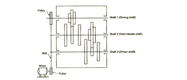
From the figure, its miles clean that the kinematic format indicates the association of gears in a equipment field. The kinematic format gives the subsequent information’s required for equipment field design.
The wide variety of speeds to be had on the spindle, i.e., on the pushed shaft. The wide variety of levels used to acquire the specified spindle speeds.
The wide variety of easy equipment trains required to reap the specified spindle speeds and their association.
The normal operating precept of the equipment field.
The facts required for structural formulation and ray diagram
In figure, the electricity is transmitted from riding shaft to pushed shaft via a intermediate shaft. In this traditional tools field, velocity converting is acquired the usage of sliding tools mechanism.
It may be visible that the quantity of speeds from riding shaft to intermediate shaft is 3, and that from intermediate shaft is 3. Then the quantity of spindle speeds is same to a few x 3 = 9. The structural method for the kinematic association of tools field proven in figure, is given by
n = p1 (X1) • p2 (X2)
Where p1 = 3 (i.e., in stage 1, there are 3 speeds available)
p2 = 3 (i.e., in stage 2, there are 3 speeds available)
X1= 1 and X2= p1 = 3
Structural formula, z = 3 (I) . 3 (3)
Where n = Number of speeds available at the driven shaft
=p1 . p2 = 3 x 3 = 9
Calculation of No. Of shaft to draw kinetic arrangement:
No. Of shafts = No. Of stages + 1 that is
If 3 stages are there in gear box design, then No. Of shaft will be (3+1 = 4 shafts)
Calculation of No. Of gears to draw kinematic arrangement:
Shaft 1 = pi gears
Shaft 2 = p1 and p2 gears
Shaft 3 = p2 and p3 gears
.
.
Shaft n = pn and pn+1 gears
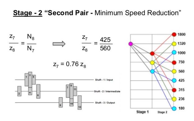
Deviation Diagram:
Deviation bar graphs are really bar charts aligned, in which one of the charts runs proper to left in preference to left to proper. The charts document at the identical classes however fluctuate in phrases of respondent organization or a few different variable.
Thus, the shared classes, which include the survey questions, are indexed with inside the area with inside the center of the 2 bar charts. Usually, those are built as bar charts, in which the bars are horizontal, now no longer column charts.
The motive of graphing every set of responses one at a time from each other is in order that it's far simpler to peer the form of every reaction set. Thus it's far vital to reserve one of the reaction units from best to least, in order that it's far simpler for a viewer to peer in which the opposite reaction set is out of form.
Key Takeaways:
- The wide variety of speeds to be had on the spindle, i.e., on the pushed shaft. The wide variety of levels used to acquire the specified spindle speeds.
- In figure, the electricity is transmitted from riding shaft to pushed shaft via a intermediate shaft. In this traditional tools field, velocity converting is acquired the usage of sliding tools mechanism.
- Thus, the shared classes, which include the survey questions, are indexed with inside the area with inside the center of the 2 bar charts. Usually, those are built as bar charts, in which the bars are horizontal, now no longer column charts.
- There are many varieties of gears along with spur gears, helical gears, bevel gears, computer virus gears, equipment rack, etc. These may be widely categorized through searching on the positions of axes along with parallel shafts, intersecting shafts and non-intersecting shafts.
- It is essential to correctly apprehend the variations amongst equipment kinds to perform essential pressure transmission in mechanical designs.
- Even after selecting the overall type, it's far essential to recall elements along with: dimensions (module, range of tooth, helix angle, face width, etc.), well known of precision grade (ISO, AGMA, DIN), want for tooth grinding and/or warmth treating, allowable torque and efficiency, etc.
- In addition to the listing below, every segment along with computer virus equipment, rack and pinion, bevel equipment, etc. has its personal extra clarification concerning the respective equipment type.
- It is exceptional to begin with the overall information of the varieties of gears as proven below. But further to those, there are different kinds along with face equipment, herringbone equipment (double helical equipment), crown equipment, hypoid equipment, etc.
- The distinction among an equipment and a sprocket simply said, an equipment meshes with any other equipment at the same time as a sprocket meshes with a series and isn't always a equipment.
- Aside from a sprocket, an object that appears extremely like an equipment is a ratchet, however its motion is confined to 1 direction.
Gear-Tooth Action
1. Fundamental Law of Gear-Tooth Action
- Tooth profile 1 drives tooth profile 2 by acting at the instantaneous contact point K.
- N1N2 is the common normal of the two profiles.
- N1 is the foot of the perpendicular from O1 to N1N2
- N2 is the foot of the perpendicular from O2 to N1N2.
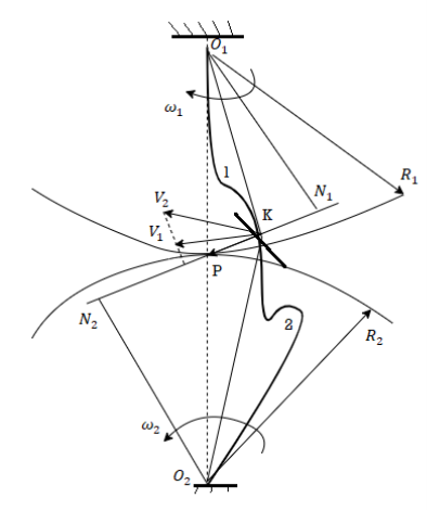
Figure: gearing tooth profiles
Although the two profiles have different velocities V1 and V2 at point K, their velocities along N1N2 are equal in both magnitude and direction. Otherwise the two tooth profiles would separate from each other. Therefore, we have

(5-1)
Or

(5-2)
We notice that the intersection of the tangency N1N2 and the line of center O1O2 is point P, and

(5-3)
Thus, the relationship between the angular velocities of the driving gear to the driven gear, or velocity ratio, of a pair of mating teeth is

(5-4)
Point P is very important to the velocity ratio, and it is called the pitch point. Pitch point divides the line between the line of centers and its position decides the velocity ratio of the two teeth. The above expression is the fundamental law of gear-tooth action.
2. Constant Velocity Ratio
For a regular pace ratio, the placement of P need to continue to be unchanged. In this case, the movement transmission among gears is equal to the movement transmission among imagined slip less cylinders with radius R1 and R2 or diameter D1 and D2. We can get circles whose facilities are at O1 and O2, and via pitch factor P. These circle are termed pitch circles. The pace ratio is same to the inverse ratio of the diameters of pitch circles. This is the essential regulation of gear-teeth action.
The fundamental law of gear-tooth action may now also be stated as follow (for gears with fixed center distance)
The not unusual place regular to the enamel profiles on the factor of touch have to continually by skip thru a set factor (the pitch factor) on the road of centers (to get a regular pace ration).
According to their tooth: parallel axis and perpendicular axis
Parallel Axis Gears
- Spur Cylindrical Gears.
- They generate radial response masses at the axis and transmit strength via parallel shafts.
- This form of equipment is the only and is normally used for small and medium speeds, because it generates noise whilst if the velocity increases.
- Helical Cylindrical Gears.
Nonparallel Axis Gears
Little used nowadays, they transmit the motion of axis which can be reduce with inside the identical plane, commonly in proper attitude, by way of conical toothed surfaces.
The enamel converge on the intersection of the axes.
They are regularly used to gradual down with axes located at ninety ranges and are noisy.
Spiral Bevel Gears.
Their touch floor is greater as compared to immediately bevel gears.
They can transmit the movement of axis which can be reduce and used to decrease the rate on shafts of ninety ranges.
Hypoid Gears.
Their assault pinion is off-middle on the subject of the axis of the crown.
They stand out for his or her lengthy carrier existence and the low noise they generate, despite the fact that they require excessive strain oils.
They are utilized in boats and business machines.
Worm Wheels and Worm Screws
They have a malicious program screw, which capabilities as a conductor, and a crown, pushed with the aid of using it.
The screw movements the crown with its turn. Although its maximum not unusual place attitude among axes is ninety ranges, it is able to be different.
Key Takeaways:
- It is essential to correctly apprehend the variations amongst equipment kinds to perform essential pressure transmission in mechanical designs.
- If it's far tough to view PDF, please seek advice from those sections.
- The distinction among an equipment and a sprocket simply said, an equipment meshes with any other equipment at the same time as a sprocket meshes with a series and isn't always a equipment.
References:
1. Design Data - P.S.G. College of Technology, Coimbatore.
2. Vehicle Powertrain Systems by Behrooz Mashadi, David Crolla. A John Wiley & Sons, Ltd
3. Automobiles–Power trains and Automobiles–Dynamics by Crolla, David, A John Wiley &Sons, Ltd
4. Automotive Engineering Powertrain, Chassis System and Vehicle Body by David A Crolla, Elsevier B H New York, London, Oxford.
5. Lack P.H. And O. Eugene Adams, Machine Design, McGraw Hill Book Co. Inc.
6. Willium C. Orthwein, Machine Components Design, West Publishing Co. And Jaico Publications House.
7. P. Kannaiah, Design of Transmission systems‖, SCIETCH Publications Pvt Ltd.
8. C.S. Sharma and Kamlesh Purohit, Design of Machine Elements, PHI Learning Pvt. Ltd.
9. D.K. Aggarwal& P.C. Sharma, Machine Design, S.K Kataria and Sons.
10. P. C. Gope, Machine Design: Fundamentals and Applications, PHI Learning Pvt. Ltd.
11. Bhandari, V. B. Machine Design data book, Tata McGraw Hill Publication Co. Ltd.
12. K. Mahadevan, K. Balveera Reddy, Design Data Handbook for Mechanical Engineers, CBS Publishers.