Unit 2
Equilibrium
Lami’s Theorem states, “When three forces acting at a point are in equilibrium, then each force is proportional to the sine of the angle between the other two forces”. Referring to the above diagram, consider three forces A, B, C acting on a particle or rigid body making angles α, β and γ with each other.
In the mathematical or equation form, it is expressed as,

Where,  is the inclination of force P with the direction of motion of the body
If 
Work done=0
Hence, if angle between the line of action of the force and direction of motion of body is 90° the work done will be zero.
Note:-
1) Work done is said to be positive if point of application of force moves in direction of force.
2) Work done is said to be negative if point of application of force moves in the direction opposite to force.
3) Work done is said to be zero if point of application of force moves at right angle to direction of force.
Virtual work
The work done by a force on body due to small virtual (i.e imaginary) displacement of the body is known as virtual work.
If we assume that body is in equilibrium under the system of forces work done is zero.
But if we assume that body is in equilibrium undergoes infinite small imaginary displacement known as virtual displacement then some work done will be imagined. Such imaginary work done is known as virtual work.
This concept of virtual work is very useful to find out unknown force in structure.
Principle of virtual work.
It states that, “If a system of forces acting on a body or system of bodies be in equilibrium and system be imagined to undergo a small displacement consistent with geometrical conditions. Then algebraic sum of virtual work done by all forces a system is zero.”
Proof:-consider a body at 0,subjected to force P incline at angle with x minus x axis as shown in figure 26.
Let,
 = components of force along x-x axis.
 =component of force along x y axis
From geometry


Now consider a body moves from 0 to some other point C under the action of force P. Such that line OC makes an angle  with direction of force. Now draw CA and CB perpendicular to ox and oy respectively as such in figure 26
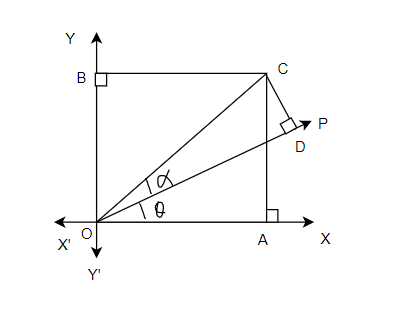
From geometry ∆OCA we find that


Similarly,

We know that sum of work done by component  of force P=


 Cos(-A)=Cos(A)
We also know that work done by force P in moving the body from 0 to L

Since equation 1 and 2 are same
Work done by force equal to sum of works done by its resolved parts.
Sign Conventions
1) Upward forces are considered as positive, whereas downward forces consider as negative.
2) Forces towards right consider as positive where as towards left as negative.
3) Forces acting in clockwise direction are consider as positive, where as anticlockwise as negative.
4) Tensile force are consider as positive where as compressive as negative.
Important points to be remembered while applying the principle of virtual work.
1.If tension t in an inextensible string to be calculated, replace the string by two forces each equal to T acting at end of string now apply principle of virtual work and calculate value of t.
2.If the reaction are at rigid support to be calculated as rigid support is not supposed to move virtual work done by rigid support will be zero hence reaction are not appear in equation of virtual and the press it by force are this force can be given a virtual displacement and value of R will be obtained by applying principle of virtual work.
3. If all forces act in same direction gives system a virtual displacement in direction of force.
4. Virtual displacement are devoted by  where as actual displacement are denoted by
  .
.
5.If roller moves horizontally then the action of roller does not do any work also when pain rotates the actions do not do any work.
Application of principle of virtual work
The principle of virtual work has verified applications but following are important from subject point of view
1.Beams
2.Lifting machine
3.framed structure
Application of principle of virtual work on Beam carrying point
Consider a beam a bi simply supported at its supports and subjected to point load w at C as shown in figure 27
Let
 =reaction at A
 =reaction at B
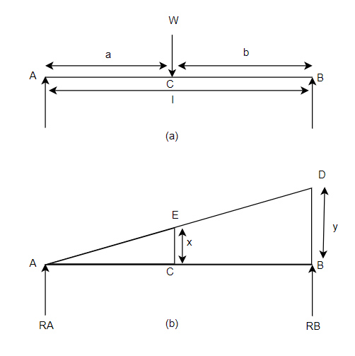
First of all letters assume beam to be linked at A. Now consider upward virtual displacement of beam at B. This is due to reaction at B acting upwards as shown in figure 27 b
Let x be upward virtual displacement of beam at C due to point load.
Now, in two similar triangles ABD and ACE


Total virtual work done by 2 reactions 


And
Virtual work due to point load= Minus sign due to load acting downward
We know that principle of virtual work, that algebraic sum of virtual work done is zero.


Similarly,

Note:-The value of  may also obtained by substituting value of
  from downward load


Application of principle of virtual work for beams carrying uniformly distributed load.
Consider a beam AB of length l simply supported at its both ends and carrying U.D.L. Of w per unit length for whole span from A to B as shown in Fig 28(a)
Let
 Reaction at A
 Reaction at B
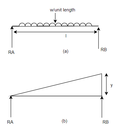
First of all let us assume the beam to hinged at A. Now consider an upward virtual displacement y of beam at B. This is due to reaction at B acting upward as shown in Fig. 28(b)
Total virtual work done by two reaction 


And
Virtual work done by U.D.L.
=

We know that
Algebraic sum of virtual work done is zero.


Example-11:-Using principle of virtual work, determine reaction of beam AB of span 8m. The beam carries a point load of 4KN at a distance 3m from A.
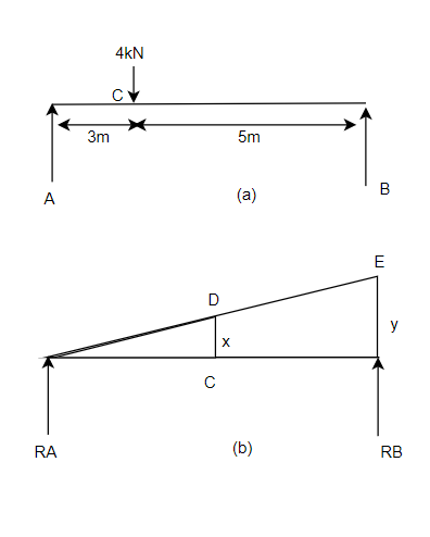
Solution:-Given:
Span of beam AB=8m
Point load=4KN
Let beam AB is given virtual displacement at B in upward direction keeping and A as hinged.
Let
y=virtual displacement at end B.
x=virtual displacement at C
 reaction at end B.
 =reaction at end A.
From similar triangle ACD and ABE


Algebraic sum of virtual work done is zero as per principle of virtual work done
Virtual work done by two reactions 


Virtual work done due to point load 4KN

Applying principle or work done


And


Example-12:-By principle of virtual work. Determine reaction for beam shown in fig.30

Distances
AD=6m AB=10m AE=10+2=12m AC=2m
Let
Reaction at A =
Reaction at B=
To determine reaction  . Let beam given virtual displacement at B in upward direction. Keeping end A intact. All points lying towards right from point A have upward virtual displacements whereas point lying towards left from A will have downward virtual displacement.
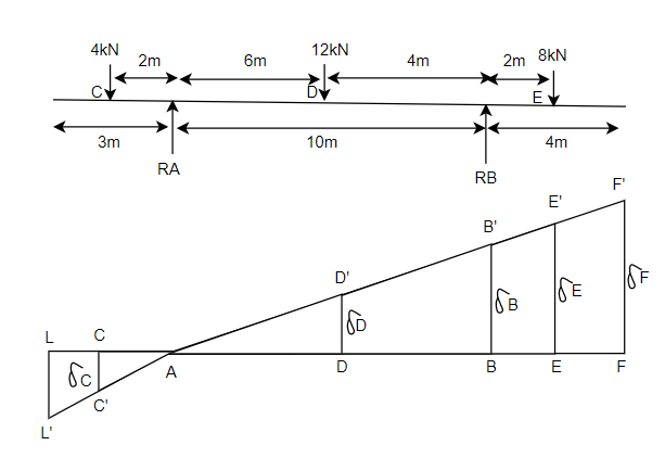
 virtual displacement at B upward direction
 virtual displacement at E upward direction
 virtual displacement at D upward direction
 virtual displacement at C upward direction
The triangles ADD’, ABB’, AEE’ and ACC’ of Fig 31 are similar


Virtual work done by reaction


Virtual work done by point load at E


Virtual work done by point load at D


Virtual work done at reaction 
Virtual work done by point load at C


Total virtual work done


From principle of virtual work total work done should be zero.


Also


Example-13:- A simply supported beam AB of span 5m is loaded as shown in Fig 32. Using principle of virtual. Find reaction at A and B.
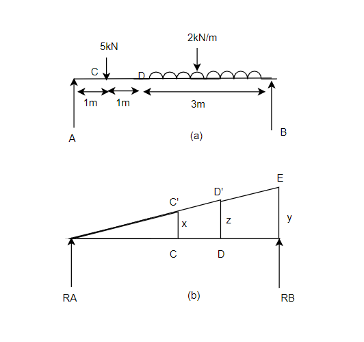
Solution:- Given
Span AB=5m
Let
 Reaction at A
 Reaction at B
Let
y, x, z be virtual displacement of beam at B, C and d respectively
From Similarity of triangle ABB’, ACC’, ADD’


x=0.2y
Also


Total virtual work done at A and B


+ve sign due to reaction acting upwards
Virtual work done due to point load at c and U.D.L. Between D and B.


Apply principle of virtual work algebraic sum of virtual work done is zero.


But


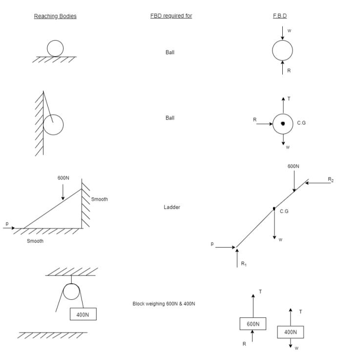
In many problems it is essential to isolate the body under consideration from the other bodies in contact and draw all forces acting on the body. For this first the body is thrown and then applied forces self weight and the reaction at point of contact with other bodies are drawn. Since a diagram of the body in which the body under consideration is free from all the contact surface and shown all the forces acting on it including reaction at contact surfaces is called free body diagram (FBD).
Table 1:-free body diagram FBD for few typical cases.
When a body is acted upon by a number of forces then the forces are replaced by single forces having same effect as produced by all given forces this force is known as resultant force little consideration will show that if resultant force of number of forces acting on body is zero then body is considered to be in equilibrium such a set of forces whose resultant is zero are called equilibrium forces.
A forces which brings the set of forces in equilibrium is called an equilibrant.
- Principles of equilibrium
They are many principles of equilibrium following 3are important from subject point of view.
- Two forces principle:-if a body in equilibrium is acted upon by two forces then they must be equal opposite and collinear.
- Three force principle:-if a body in equilibrium is acted upon by three forces and resultant of any two force must be equal opposite and collinear with third force.
- Four force principal:-if a body in equilibrium is acted upon by four forces the resultant of any two forces must be equal opposite and Collinear with resultant of other two forces.
A beam may be defined as structural element which has one dimension considerable larger than other two dimensions namely breadth and depth and is supported at few points distance between two adjacent supports called span.
It is usually loaded normal to it except the applied load makes every cross section to fourth bending and sharing the lowered finally gets transformed to supports the system of forces consisting of applied load and reactions at supports keep beam in equilibrium
The reaction depends upon type of support and types of loading
- Types of support
- Simple support:-If the beam rest simply on a support it is gold simple support reaction at support is at right angles to support and beam is free to move and direction of x-axis and also it is free to rotate about support.
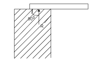
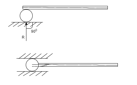
2. Roller support:-In this case beam and is supported on rollers in such cases recution is normal to support since roller can considered as friction less beam is free to move along the support it can rotate about support also.
3. Hinged support:-At a hinged end a beam cannot move in any direction however it can rotate about support hence support will not develop any existing moment but It can develop reaction in any direction to keep beam study the reaction are can be split into its horizontal and vertical component for analysis purpose.
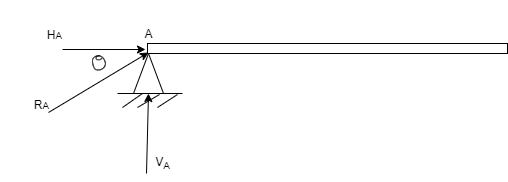
From above diagram


4. Fixed support:-As such support beam is not free to rotate or translate translation is prevented by developing support reaction in any required direction.
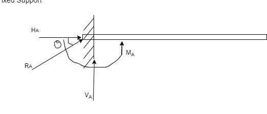
From above figure


- Types of beam:-
- Simple supported beam:-when both ends of beam are simply supported it is called simply supported beam
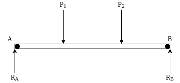
Such beam can support load in direction normal to its axis.
2. Beam with one end hinged and other an rollers
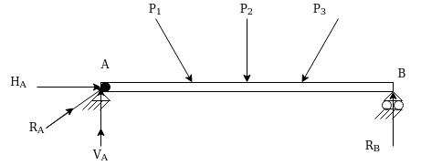
Such beam can resist load in any direction.
3. Overhanging beam:-A beam is projecting beyond support it called overhanging beam.

4. Cantilever beam:-if beam is fixed at one end and other end is freed it called cantilever beam.

5. Propped cantilever:-if beam is fixed at one end and other end is simply supported is called propped cantilever.
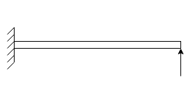
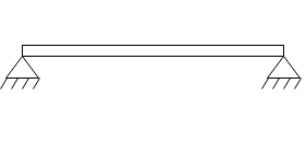
6. Both ends hinged:-in this being both ends are having hinged supports
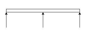
7. Continuous beam:-beam is said to be continuous if it is supported at more than two points.
Note:-1. Statically determinate:-The beam which can be analysed using only equilibrium equations are known as statically determinate beam.
Simply supported beams, beams with one and hinged and other on rollers cantilever even and overhanging beams are it is possible to determine the reactions for given conditions by using equilibrium equations only.
2. Statically indeterminate:-The beam which cannot be analysed using only equilibrium equations are known as statically indeterminate beam .In this type of beam number of independent equations are less than number of unknown reactions and it is not possible to analyse them by equilibrium equations alone.
- Types of loading:-
- Concentrated loads:-if a load is acting on beam over a small length it is approximated as acting at mid point of that length and represented by an arrow as shown in figure
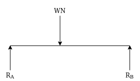
Where W= applied load
2. Uniformly distributed load (UDL):-over considerable long-distance much load has got uniform intensity it is represented as shown in figure.

For finding reaction this load may be as total load. Load acting at centre of gravity of loading ( middle of loaded length).
From above figure we can say that
Total load=Wx
Load acting at=
Distance measured from starting point of VDL
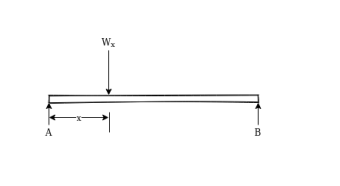
3. Uniformly varying load:-the load shown in below figure where is uniformly from C to D it intensity is zero at c and d. W N/m at D. In lower diagram the orchinate represents the load intensity and represents the position of load on beam
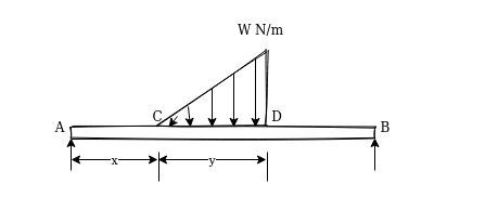
From above figure we can say that
Total load=
i.e area of triangle represent total load
Centroid of triangle represent centre of gravity of load.
Centre of gravity of this loading is at
From D i.e 
General loading:-following figure represents general loading
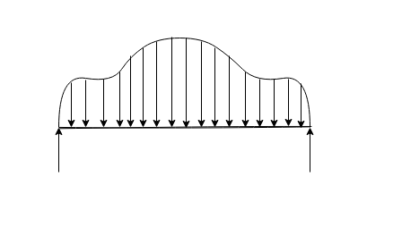
Hair ordinate represent intensity of loading and C present position of load on beam for simplicity in analysis such holding or replaced by a set of equivalent concentrated loads.
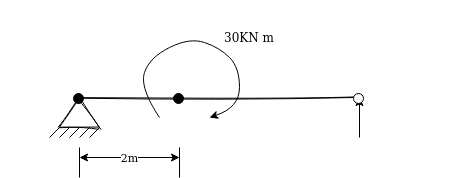
4. External moments:-a bi may be subjected to external moments at certain point following figure represent beam subjected to clockwise moment of 30 kN.m 8 distance 2m from left support
Reference Books
1.Engineering Mechanics by S. S. Bhavikattis, New Age International Pvt. Ltd.
2.Engineering Mechanics by R. K. Bansal and Sanjay Bansal.
3.Vector Mechanics for Engineers Vol.I and II by F. P. Beer and E. R. Johnston, Tata Mc-Graw Hill Publication.
4.Engineering Mechanics by Manoj K Harbola, Cengage Learning
5.Engineering Mechanics by K. I. Kumar, Tata Mc-Graw Hill Publication
6.Engineering Mechanics by S. B. Junnerkar.
7.Engineering Mechanics by Irving H. Shames, Prentice Hall of India, New Delhi.
8.Applied Mechanics by S. N. Saluja, Satya Prakashan, New Delhi.
9.Engineering Mechanics by Statics and Dynamics by Ferdinand Singer, Harper and Row Publications
10.Engineering Mechanics by R. S. Khurmi, S. Chand Publications
11.Fundamentals of Engineering Mechanics by S. Rajasekaran, G. Sankarasubramanian,VikasPublishing House
12) “Applied Mechanics- Dynamics &Statics ” by I.B.Prasad, Khanna Publisher, Delhi