Unit 1
Analysis of D.C. Circuits
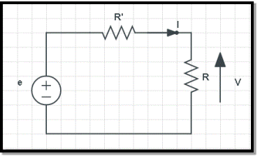
Electromotive force is defined as the electric potential produced by either electrochemical cell or by changing the magnetic field. The acronym for electromotive force is E.M.F.
An electromotive force is a work done on a unit electric charge.
Electromotive force is used in the electromagnetic flowmeter which is an application of Faraday’s law.
The symbol of electromotive force is ε and the unit for electromotive force is Volt.
The formula of electromotive force:
ε = V + IR
Where,
- V is the voltage of the cell
- I is the current across the circuit
- R is the internal resistance of the cell
- ε is the electromotive force
The amount of work done to carry a unit charge from one point to another in an electric field is called as the electrical potential difference. In other words, the potential difference is defined as the difference in the electric potential of the two charged bodies.
Unit of Potential Difference: The unit of potential difference is Volt(V).
1.3.1 Current
An electric current is a flow of electric charge in a circuit. More specifically, the electric current is the rate of charge flow past a given point in an electric circuit. The charge can be negatively charged electrons or positive charge carriers including protons, positive ions or holes.
The magnitude of the electric current is measured in coulombs per second, the general unit for current is Ampere or amp which is designated by the letter ‘A’.
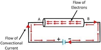

In the above figure, the current(I) flows in opposite direction i.e. from point A to B , to the flow of electrons through the conductor which is from point B to A.
1.3.2 Resistance
Resistance is a opposition offered to the current flowing in any electrical circuit. It is measure in terms of ohms, which is symbolized by the Greek letter omega (Ω)
From the definition, it can be said that the unit of electric resistance is volt per ampere.
One unit of resistance is such a resistance which causes 1 ampere current to flow through it when 1 volt potential difference is applied across the resistance.

The unit of electric resistance is volt per ampere which is called as ohm(Ω) after the name of great German physicist George Simon Ohm.
1.4.1 Ohm’s Law
Statement - Ohm’s Law states that the current flowing through a conductor is directly proportional to the potential difference applied across its ends, provided the temperature and other physical conditions remain unchanged. Mathematically it can be represented as,
Potential difference ∝ Current
V ∝ I
(When the value of V increases the value of I increases simultaneously)
V = IR ………………………. (eq.1)
Where,
- V is Voltage in volts (V)
- R is Resistance in ohm (Ω)
- I is Current in Ampere (A)
Calculating Various Parameters Using Ohm’s Law
As an equation (eq.1), the Ohm’s Law serves as master for calculating the current (I), when the resistance (R) and the potential difference (V) are known. Similarly, if any two parameters in the equation (eq.1) are known, then the unknown third one can be easily calculated as follows:
- To find Voltage(V),
V = IR …………………………… (eq.2)
- To find Current(I),
I=VR ……………………………… (eq.3)
- To find Resistance(R),
R=VI ……………………………… (eq.4)
1.4.2 Kirchhoff’s Law
Kirchhoff’s Current Law (KCL)
Statement - The algebraic sum of currents meeting at a junction or node in a electric circuit is zero or the summation of all incoming current is always equal to summation of all outgoing current in an electrical network.
Explanation
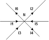
Assuming the incoming current to be positive and outgoing current negative we have


I e incoming current = ∑ outgoing current thus, the above Law can also be stated as the sum of current flowing towards any junction in an electric circuit is equal to the sum of currents flowing away from that junction.
Kirchhoff’s Voltage Law (KVL)
Statement : the algebraic summation of all Voltage in any closed circuit or mesh of loop zero.
i.e,
∑ Voltage in closed loop = 0 , the summation of the Voltage rise (voltage sources) is equal to summation of the voltage drops around a closed loop in 0 circuit for explanation from here
Determination of sigh and direction of currents (Don’t write in exams just for understanding)

Current entering a resistor is +ve and leaving should be –ve
Now
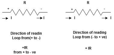


Potential Rise Potential Drop
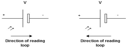
We are reading from +V to –V we are reading from –V to +V
 potential drops
  potential rise
 -V
-V  +V
+V
Given Circuit
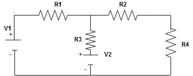
First identify no of loops and assign direction of current flowing in loop
Note : no of loops in circuit = No, of unknown currents = no. Of equations in the circuit
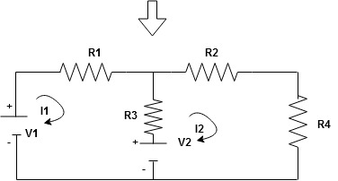
Note : keep loop direction and current direction same ie either clockwise or anticlockwise for all loops I1 I2
Now according to direction of direction assign signs (+ve to –ve) to the resistors
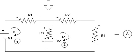
Note : voltage sources (V) polarities does not change is constant.
Note: for common resistor between 2 loops appearing in the circuit like R3 give signs according to separate loops as shown
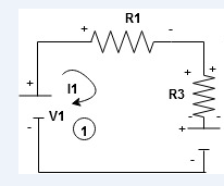
When considering only loop no 1 (+ R3 - )
- B
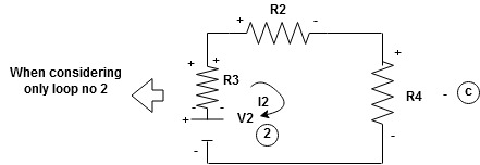
Now consider diagram A and write equations
Two loops  two unknown currents
  two equation
Apply KVL for loop ① [B. Diagram ]
(+ to drop -) = - sign and (- to rise +) = + sign
 for drop = -sign
 for rise = + sign
-
-( ) R2 is considered because in R3,2 currents are flowing
  and
and  and we have taken (
 ) because we are considering loop no 1 and current flowing is
  in loop no 1
 )
)
Similarly for loop no. 2 currents flowing is  resistor R3 it should be
  )R3
)R3
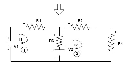
Consider loop no. 1 apply KVL
- …….①
…….①
-
Consider loop no. 2 apply KVL
- …….②
…….②
-
After solving equation ① and ② we will get branch current  and
and 
(Numerical on Mesh and Nodal Analysis of Two loops)
Nodal analysis
In the nodal method we are finding the node voltages with the following steps:
- Select a reference node. Assign all the rest nodes voltages , with respect to reference node.
- Use Kirchhoff’s and Ohm’s Laws to each non-reference node and branch currents.
- Resolve the system of equations and obtain node voltages.
Consider the following circuit.

Let us consider a reference node – 3.
In a real circuit a reference node is ground is assumed to have potential.
By the Kirchhoff’s Law having the following current relation:
I1 = i1 + i2
I2 = i2 -i3
Let us represent currents like ratio of voltage and resistance by the Ohm’s Law:
i 1 = v1 /R1 ;i 2 = v1 -v2 /R2 ; i3 = v2/R3;
Or
i 1= v1 * G1 ; i2 =(v1 -v2)*G2 ; i3 =v2 * G3
i1 = v1 * G1 + (v1-v2) * G2 ;
i2 = (v1-v2) * G2 – v2 * G3
i1= v1 * (G1 +G2) – v2 * G2
i2 = v1 *G2 – v2 *(G3 +G2)
Or
And we achieve the following matrix equation, which can be resolved by the Cramer’s rule:
[ G1 + G2 -G3 -G3 ] [v1] = [I1]
[ G2 -G2][v2] =[I2]
Consider the following figure :
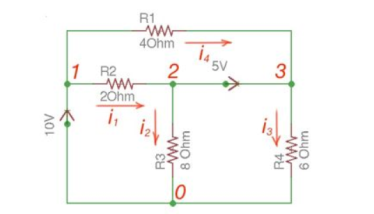
There are two possibilities that exist:
- If the voltage source is between reference node and non-reference node, the non-reference voltage is considered equal to the voltage source.
- If the voltage source is between two non-reference nodes, these two nodes are generalised nodes. To determine its voltage Kirchhoff’s Laws must be applied.
Applying Kirchhoff’s Law we achieve the following equations:
i 1 + i4 = i2 + i3
-v2 +5+v3 =0
v 1 =10
By Ohm’s Law
These equations will help determine node voltages.
Mesh Analysis
Mesh analysis is applicable to the networks which are planar. Planar network is a network where branches are not passing over or under each other.
Nodal method uses Kirchhoff’s currents Law to consider nodal voltages, and Mesh method uses Kirchhoff’s voltages Law to consider mesh currents. Mesh is a loop, which does not contain any other loops.

There are only two meshes in abefa and bcdeb, abcdefa is not a mesh but a loop However, for Mesh method only meshes are in use.
Mesh analysis steps are the following:
- Assign mesh currents to all the meshes in a circuit.
- Apply Kirchhoff’s voltage Law to each mesh. Apply Ohm’s Law to determine voltages with mesh currents.
- To resolve simultaneously all the equations to consider mesh currents.
The following equations correspond to the Kirchhoff’s Voltage Laws for the meshes:
V1 = i1 *(R1+R3) – i2 *R3
-V2 = -i1 *R3 + i2 * (R3 +R2);
[ R1 +R3 -R3 [i1]= [V1]
-R3 R2+R3] [i2] = [V2]
Using Cramer’s formula for resolving the matrix equations above we can find mesh currents.
I1 =i 1 I2 = i2 I1 -I2 =i3
Q1.Find the current flowing through 20 Ω resistor of the following circuit using Nodal analysis.

Step 1 − There are three principle nodes in the above circuit. Those are labelled as 1, 2, and 3 in the following figure. In the above figure, consider node 3 as reference node (Ground).

Step 2 − The node voltages, V1 and V2, are labelled in the following figure.
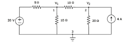
Step 3 –There are two nodal equations, since there are two principal nodes, 1 and 2, other than Ground.
The nodal equation at node 1 is
V1 -20/5 + V1/10 + V1-V2/10 =0
2V1 -40 +V1+V1-V2/10 =0
4V1 -40-V2 =0 --- V2 = 4V1-40 -------(1)
The nodal equation at node 2 is
-4 +V2/20 + V2-V1/10 =0
-80 + V2 + 2 V2 – 2V2/ 20 =0
= 3V2 -2V1 =80 --------------(2)
Step 4 − Finding node voltages, V1 and V2 by solving Equation 1 and Equation 2.
Substitute Equation 1 in Equation 2.
3(4V1−40)−2V1=80
⇒12V1−120−2V1=80
⇒10V1=200
⇒V1=20V
Substitute V1 = 20 V in Equation1.
V2=4(20)−40
⇒V2=40V
So, we got the node voltages V1 and V2 as 20 V and 40 V respectively.
Step 5 − The voltage across 20 Ω resistor is nothing but the node voltage V2 and it is equal to 40 V. Now, we can find the current flowing through 20 Ω resistor by using Ohm’s law.
I 20Ω = V2/R
Substitute the values of V2 and R
I 20 Ω = 40/20
I 20Ω = 2A
Therefore, the current flowing through the 20Ω resistor is 2A.
Q2.Find the voltage across 30 Ω resistor using Mesh analysis.

Step 1 − There are two meshes in the above circuit. The mesh currents I1 and I2 are considered in clockwise direction. These mesh currents are shown in the following figure.

Step 2 − The mesh current I1 flows through 20 V voltage source and 5 Ω resistor. Similarly, the mesh current I2 flows through 30 Ω resistor and -80 V voltage source. But, the difference of two mesh currents, I1 and I2, flows through 10 Ω resistor, since it is the common branch of two meshes.
Step 3 −Since there are two meshes in the given circuitwrite the mesh equations, assume the mesh current of that particular mesh as greater than all other mesh currents of the circuit.
The mesh equation of first mesh is
20−5I1−10(I1−I2)=0
⇒20−15I1+10I2=0
⇒10I2=15I1−20
Divide the above equation with 5.
2I2=3I1−4
Multiply the above equation with 2.
4I2=6I1−8-----------------(1)
The mesh equation of second mesh is
−10(I2−I1)−30I2+80=0
Divide the above equation with 10.
−(I2−I1)−3I2+8=0
⇒−4I2+I1+8=0-----------------(2)
4I2 = I1 +8
Step 4 − Finding mesh currents I1 and I2 by solving Equation 1 and Equation 2.
The left-hand side terms of Equation 1 and Equation 2 are the same. Hence, equate the right-hand side terms of Equation 1 and Equation 2 in order find the value of I1.
6I1 -8 = I1 +8
5I1 =16
I1 = 16/5 A
Hence, 4I2 = 16/5 + 8
4I2 = 56/5
I2 = 56/20 = 2.8 A
Step 5 − The current flowing through 30 Ω resistor is nothing but the mesh current I2 and it is equal to 14/5 A. The voltage across 30 Ω resistor by using Ohm’s law.
V 30 Ω = I2 R
V30Ω = (14/5) x 30 = 84V
Q3. Using nodal analysis find voltage across 5resistor.
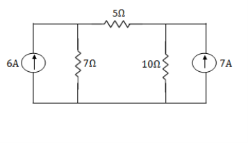
Solution:
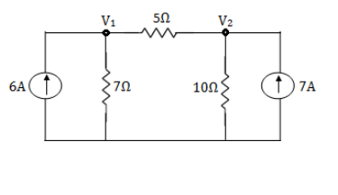
For V1


 1
1
For V2


 2
2
Solving 1 and 2:


For 5 voltage = 
= -50.9 + 57.27
= 6.37V