Unit 2
Magnetic circuits
Due to the existence of electromotive force ,the current flows in an electric circuit similarly magnetomotive force (MMF) is required to drive the magnetic flux in the magnetic circuit. The Magnetomotive Force is the magnetic pressure, which sets up the magnetic flux in a magnetic circuit.
The SI unit of MMF is Ampere-turn (AT), and their CGS unit is G (gilbert).
2.2.1. Reluctance
Reluctance is the obstruction offered by a magnetic circuit to the magnetic flux. As, there is resistance in electric circuit similarly in the magnetic circuit, there is a reluctance and resistance in an electrical circuit dissipates the electric energy but the reluctance in magnetic circuit stores the magnetic energy.
2.2.2. Magnetic flux
The Magnetic Flux is number of magnetic lines of forces set up in a magnetic circuit. It is analogous to electric current, I in an electric circuit.
Its SI unit is Weber (Wb) and its CGS unit is Maxwell.
It is denoted by φm.
The magnetic flux measures through flux meter.
The force acting per unit current per unit length on a wire placed at right angles to the magnetic field is called as Magnetic flux density (B).
- Units of B is Tesla (T) or Kgs−2A−1
- Magnetic Flux Density (B) is a vector quantity
Magnetic Flux Density Units are :-
SI unit- Tesla (abbreviated as T)
CGS unit- Gauss (abbreviated as G or Gs)
The ratio of the MMF which is required to create a certain Flux Density within a certain material per unit length of that material is called as Magnetic Field Strength. It is also called as the magnetic field intensity.
The unit of magnetic field strength happens to be ampere per meter or A/m.
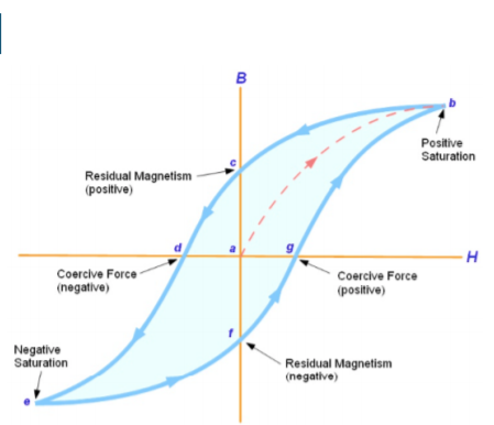
2.5.1 BH curve

- When tested experimentally, a ferromagnetic material such as iron will produce a curve similar to that shown above.
- First there is an upper/lower limit to the magnetic flux density which may be achieved, which occurs at positive or negative saturation, respectively. This is related to the crystalline structure of the iron, where each crystal has its own – initially random – magnetic orientation.
- Increasing the magnetic field strength in either direction causes more and more magnetic 'domains' to align with the external magnetic field, but once almost all of the domains have aligned themselves, then little further increase in magnetic flux density is possible. The ferromagnetic material is said to be saturated.
- The curve demonstrates magnetic hysteresis or 'lag' as the sample is alternatively magnetized in the positive and negative directions. When initially magnetized, the curve follows points a–b on the graph, but on reducing H to zero, some residual magnetism remains (point c - also known as the remnant flux density).
- In order to fully demagnetize the specimen, it is necessary to apply a negative magnetic field strength (point d - called the coercive force). Making H increasingly negative leads to negative saturation (point e). If H is reduced back to zero, point f is reached (negative residual magnetism). As H becomes positive, the flux density reduces to zero (point g) and then becomes positive.
- Finally returning back to point b (positive saturation), after which the cycle b–g repeats. The area enclosed by the B-H curve (shaded light blue above) is proportional to the energy loss as the ferromagnetic material is magnetized with varying polarity by connection to an alternating (AC) power supply.
- This energy loss is undesirable and causes unwanted heating of the material. In general, harder ferromagnetic materials have higher hysteresis losses, since more energy is required to realign the magnetic domains. Steel, to which a small proportion of silicon has been added, is commonly used for applications such as transformer cores and motor rotors, due to its lower hysteresis loss.
For smaller applications, such as inductor cores, passive filters, miniature transformers and antennas, then ferrite (a ceramic-like combination of metallic oxides including ferric oxide) is a popular choice
2.5.2 Magnetic Leakage
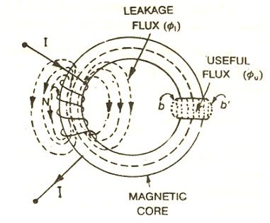
Magnetic Leakage is defined as the magnetic flux which does not follow the particularly intended path in a magnetic circuit. In other words, it can be defined as the passage of magnetic flux outside the path along which it can do useful work.
2.6.1 Fringing
 fig. Solenoid
When a current is passed through a solenoid, it produces magnetic flux.
In the core of the solenoid, most of the flux is set up and passes through the particular path that is through the air gap and is used in the magnetic circuit. This flux is known as Useful flux φu.
In the air gap when the useful flux sets up in the air gap, it tends to bulge outward at (b and b’) as shown in above figure, because of this bulging, the effective area of the air gap increases and the flux density of the air gap decreases. This effect is known as Fringing.
Fringing is directly proportional to the length of the air gap that means if the length decreases the fringing effect will also be less and vice versa.
2.6.2 Comparison of Electric and Magnetic circuit
Electric circuit | Magnetic circuit |
|
|
|
|
|
|
|
|
|
|
|
|
The magnetic circuit having a number of parts of different dimensions and materials carrying the same magnetic field is called as the Series Magnetic Circuit.