Unit 3
Single phase AC Circuits
Faraday’s law of electromagnetic induction, also known as Faraday’s law was proposed in the year 1831 by an experimental physicist and chemist named Michael Faraday. It is the basic law of electromagnetism which helps us to predict how a magnetic field would interact with an electric circuit to produce an electromotive force (EMF). This phenomenon is known as electromagnetic induction.
Faraday’s Laws of Electromagnetic Induction comprises of two laws. The first law describes the induction of emf in a conductor and the second law quantifies the emf produced in the conductor.
Faraday’s First Law of Electromagnetic Induction-
Whenever a conductor is placed in a varying magnetic field, an electromotive force is induced. If the conductor circuit is closed, a current is induced which is called induced current.
Faraday’s Second Law of Electromagnetic Induction-
The induced emf in a coil is equal to the rate of change of flux linkage.
ε=−N (Δϕ /Δt)
Where,
- ε is the electromotive force
- Φ is the magnetic flux
- N is the number of turns
The negative sign represents that the direction of the induced emf and change in the direction of magnetic fields have opposite signs.
When the flux linking with a conductor or coil changes, then an Electromotive Force or EMF is said to be induced.
By two different ways the change in flux can be obtained which is either by statically or by dynamically induced emf.
1. STATICALLY INDUCED EMF
Statically induced EMF is induced by keeping the coil and the magnetic field system, stationary at the same time, which means that the change in flux linking with the coil takes place without either moving the conductor (coil) or the field system.
This change of flux produced by the field system linking with the coil is obtained by changing the electric current in the field system.
It is further divided in two ways-
- Self-induced electromotive force (emf which is induced in the coil because of the change of flux produced by the coil linking with its own turns.)
- Mutually induced electromotive force(emf which is induced in the coil because of the change of flux produced by different coil, linking with it.)
2. DYNAMICALLY INDUCED EMF
When the magnetic field system is kept stationary, and the conductor is moving, or the magnetic field system is moving, and the conductor is stationary. Thus, by following either of the two process the conductor cuts across the magnetic field and the dynamically induced electromotive force is induced in the coil.
This phenomenon takes place in electric generators and back emf of motors and also in transformers.
Sinusoidal Waveform Construction
Coil Angle ( θ ) | 0 | 45 | 90 | 135 | 180 | 225 | 270 | 315 | 360 |
e = Vmax.sinθ | 0 | 70.71 | 100 | 70.71 | 0 | -70.71 | -100 | -70.71 | -0 |
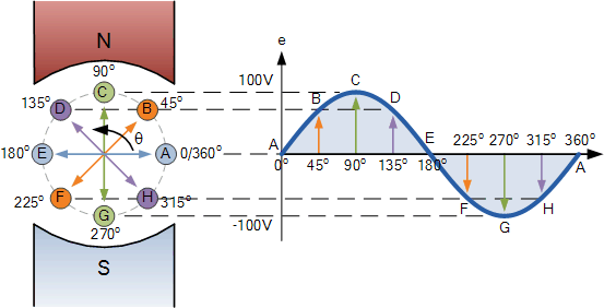
The points on the sinusoidal waveform are obtained by projecting across from the various positions of rotation between 0o and 360o to the ordinate of the waveform that corresponds to the angle, θ and when the wire loop or coil rotates one complete revolution, or 360o, one full waveform is produced.
From the plot of the sinusoidal waveform we can see that when θ is equal to 0o, 180o or 360o, the generated EMF is zero as the coil cuts the minimum amount of lines of flux. But when θ is equal to 90o and 270o the generated EMF is at its maximum value as the maximum amount of flux is cut.
Therefore a sinusoidal waveform has a positive peak at 90o and a negative peak at 270o. Positions B, D, F and H generate a value of EMF corresponding to the formula: e = Vmax.sinθ.
Then the waveform shape produced by our simple single loop generator is commonly referred to as a Sine Wave as it is said to be sinusoidal in its shape. This type of waveform is called a sine wave because it is based on the trigonometric sine function used in mathematics, ( x(t) = Amax.sinθ ).
3.5.1. Concept of R.M.S
RMS value: Root mean square value
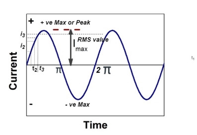
The RMS value of AC current is equal to the steady state DC current that required to produce the same amount of heat produced by ac current provided that resistance and time for which these currents flows are identical.

I rms = 
Direction for RMS value:
Instantaneous current equation is given by
i = Im Sin 
But 
I rms = 
= 
=
=
Solving
=
=
Similar we can derive
V rms=  or 0.707 Vm
 the RMS value of sinusoidally alternating current is 0.707 times the maximum value of alternating current.
3.5.2.Average Value:
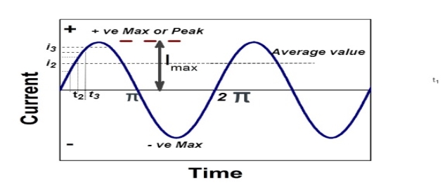
The arithmetic mean of all the value over complete one cycle is called as average value

 =
= 
For the derivation we are considering only hall cycle.
Thus  varies from 0 to ᴫ
i = Im Sin


Solving
We get


Similarly, Vavg=
The average value of sinusoid ally varying alternating current is 0.636 times maximum value of alternating current.
The ratio of the root mean square value to the average value of an alternating quantity (current or voltage) is called Form Factor.


Where,
Iav and Eav are the average value of the current and the voltage respectively, and Ir.m.s and Er.m.s are the roots mean square value of the alternating current and the voltage respectively.
Peak Factor is defined as the ratio of maximum value (peak value or the crest value or the amplitude of the voltage or current) to the R.M.S value of an alternating quantity. The alternating quantities can be voltage or current.

Where,
Im and Em are the maximum value of the current and the voltage respectively, and Ir.m.s and Er.m.s are the roots mean square value of the alternating current and the voltage respectively.
The circuit containing only a pure resistance of R ohms in the circuit is known as Pure Resistive Circuit. The presence of inductance and capacitance does not exist in a purely resistive circuit.
In the purely resistive circuit, the power is dissipated by the resistors and the phase of the voltage and current remains same i.e., both the voltage and current reach their maximum value at the same time. The resistor is the passive device which neither produce nor consume electric power. It converts the electrical energy into heat.
The circuit containing only inductance (L) and not any other quantities like resistance and capacitance in the circuit is called a Pure inductive circuit. In this type of circuit, the current lags behind the voltage by an angle of 90 degrees.
The inductor is a type of coil which reserves electrical energy in the magnetic field when the current flow through it. The inductance is measured in Henry. The opposition of flow of current is known as the inductive reactance.
The circuit which contains only a pure capacitor of capacitance C farads is known as a Pure Capacitor Circuit. In pure AC capacitor circuit, the current leads the voltage by an angle of 90 degrees.
The capacitors stores electrical power in the electric field, their effect is known as the capacitance. It is also called the condenser. The capacitor contains two conductive plates which are distanced from one another by the dielectric medium. The dielectric material is made up of glass, paper, mica, oxide layers, etc.
Series R-L Circuit
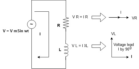
Consider a series R-L circuit connected across voltage source V= Vm sin wt
As some I is the current flowing through the resistor and inductor due do this current voltage drops arcos R and L R  VR = IRand L
 VL = I X L
 Total V = VR + VL
V = IR + I X L  V = I [R + X L]


Take current as the reference phasor : 1) for resistor current is in phase with voltage 2) for Inductor voltage leads current or current lags voltage by 90 0.
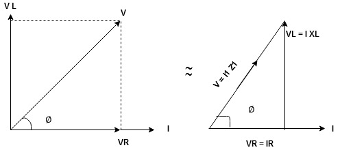
For voltage triangle
Ø is power factor angle between current and resultant voltage V and
V = 

V = 

Where Z = Impedance of circuit and its value is  =
= 
Impedance Triangle
Divide voltage triangle by I
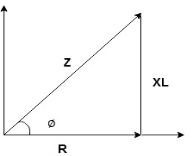
Rectangular form of Z = R+ixL
And polar from of Z =  L +
L + 
(+ j X L + because it is in first quadrant )
Where  =
= 
 + Tan -1
Current Equation :
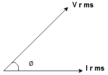
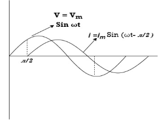
From the voltage triangle we can sec. That voltage is leading current by  or current is legging resultant voltage by
Or i =  =
=  [ current angles - Ø )

Resultant Phasor Diagram from Voltage and current eqth.
Wave form
Power equation
P = V .I.
P = Vm Sin wtIm Sin wt – Ø
P = VmIm (Sin wt) Sin (wt – Ø)
P =  (Cos Ø) - Cos (2wt – Ø)
Since 2 sin A Sin B = Cos (A-B) – Cos (A+B)
P =  Cos Ø -
  Cos (2wt – Ø)

①②
Average Power
Pang =  Cos Ø
Cos Ø
Since ② term become zero because Integration of cosine come from 0 to 2ƛ
 pang = Vrms Irms cos Ø watts.
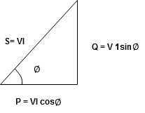
Power Triangle :
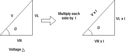
From 
VI = VRI + VLI B
Now cos Ø in  A =
A =
 ①
①
Similarly Sin  =
= 


Apparent Power Average or true Reactive or useless power
Or real or active
-Unit (VI) Unit (Watts) C/W (VAR) denoted by (Ø)
Denoted by [S] denoted by [P]
Power  for R L ekt.
13.12.2. Series R-C circuit
V = Vm sin wt
VR

 I
I
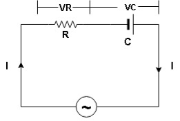
- Consider a series R – C circuit in which resistor R is connected in series with capacitor C across a ac voltage so use V = VM Sin wt (voltage equation).
- Assume Current I is flowing through
R and C  voltage drops across.
R and C  R
R  VR = IR
And C  Vc = I
 c
c


 V =
V =  lZl
lZl
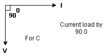
Voltage triangle : take current as the reference phasor 1) for resistor current is in phase with voltage 2) for capacitor current leads voltage or voltage lags behind current by 900
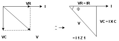
Where Ø is power factor angle between current and voltage (resultant) V
And from voltage
V = 
V = 
V = 
V =  lZl
lZl
Where Z = impedance of circuit and its value is lZl = 
Impendence triangle :
Divide voltage  by
by  as shown
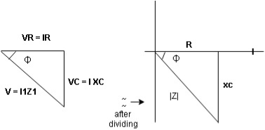
Rectangular from of Z = R - jXc
Polar from of Z = lZl L - Ø
( - Ø and –jXc because it is in fourth quadrant ) where
LZl = 
And Ø = tan -1 
Current equation :
From voltage triangle we can see that voltage is lagging current by Ø or current is leading voltage by Ø
 i = IM Sin (wt + Ø) since Ø is +ve
Or i =  for RC
 LØ [ resultant current angle is + Ø]
Resultant phasor diagram from voltage and current equation

Resultant wave form :
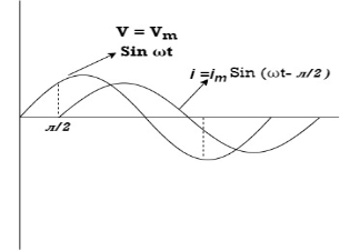
Power Equation :
P = V. I
P = Vm sin wt. Im Sin (wt + Ø)
= VmIm sin wt sin (wt + Ø)
2 Sin A Sin B = Cos (A-B) – Cos (A+B)
 -
- 
Average power
Pang =  Cos Ø
Cos Ø
Since 2 terms integration of cosine wave from 0 to 2ƛ become zero
 2 terms become zero
 pang =VrmsIrms Cos Ø
Power triangle RC Circuit:
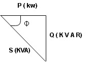
13.12.3. R-L-C series circuit
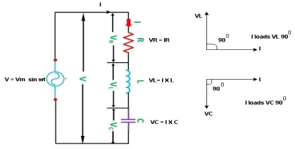
Consider ac voltage source V = Vm sin wt connected across combination of R L and C. When I flowing in the circuit voltage drops across each component as shown below.
VR = IR, VL = I  L, VC = I
  C
C
- According to the values of Inductive and Capacitive Reactance I e XL and XC decides the behaviour of R-L-C series circuit according to following conditions
① XL> XC, ② XC> XL, ③ XL = XC
① XL > XC: Since we have assumed XL> XC
 Voltage drop across XL> than XC
 VL> VC A
- Voltage triangle considering condition A

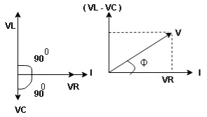
VL and VC are 180 0 out of phase .
Therefore cancel out each other
 Resultant voltage triangle
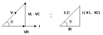
Now V = VR + VL + VC c phasor sum and VL and VC are directly in phase opposition and VL
 VC
VC their resultant is (VL - VC).
From voltage triangle
V = 
 V =
V = 
 V = I
V = I 

Impendence  : divide voltage
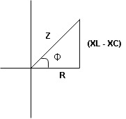
Rectangular form Z = R + j (XL – XC)
Polor form Z =  l + Ø B
Where  =
= 
And Ø = tan-1 
- Voltage equation : V = Vm Sin wt
- Current equation
i =  from B
i =  L-Ø C
L-Ø C
As VL VC the circuit is mostly inductive and
  I lags behind V by angle Ø
 Since i =
  L-Ø
L-Ø
 i = Im Sin (wt – Ø) from c
- XC
 XL :Since we have assured XC
  XL
XL
 the voltage drops across XC
  than XL
 XC
XC  XL (A)
 voltage triangle considering condition (A)
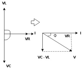
 Resultant Voltage
Now V = VR + VL + VC  phases sum and VL and VC are directly in phase opposition and VC
 VL
VL  their resultant is (VC – VL)
From voltage 
V = 
V = 
 V =
V = 
 V =
V = 

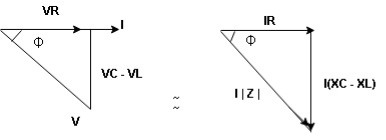
 Impedance
  : Divide voltage
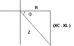
- Rectangular form : Z + R – j (XC – XL) – 4thqurd
Polar form : Z =  L -
L -
Where 
And Ø = tan-1 – 
- Voltage equation : V = Vm Sin wt
- Current equation : i =
 from B
 - i =
 L+Ø C
L+Ø C
As VC  the circuit is mostly capacitive and
  leads voltage by angle Ø
Sincei =  L + Ø
L + Ø
 Sin (wt – Ø) from C
- Power
 :
:
- XL= XC (resonance condition):
ɡȴ XL= XC then VL= VC and they are 1800 out of phase with each other  they will cancel out each other and their resultant will have zero value.
Hence resultant V = VR and it will be in phase with I as shown in below phasor diagram.
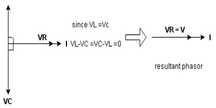
From above resultant phasor diagram
V =VR + IR
Or V = I  lZl
lZl
Because lZl + R
Thus Impedance Z is purely resistive for XL = XCand circuit current will be in phase with source voltage.
 Since VR=V Øis zero when XL = XC
  power is unity
Ie pang = VrmsI rms cos Ø = 1 cos o = 1
Maximum power will be transferred by condition. XL = XC
3.13.1. Powers
- Apparent power (S) : it is defined as product of rms value of voltage (V) and current (I) or it is the total power / max power
S = V 
 Unit - volt – Ampere (VA)
In kilo – K. V. A.
2. Real power / true power / active power / useful power : [P] it is defined as the product of rms value active component or it is the average power or actual power consumed by the resistive part (R) in the given combinational circuit
It is measured in watts
P = VI Cos Ø watts /km where Ø is the power factor angle
3. Reactive power / Imaginary / useless power [Q]
It is defined as the product of voltage current and sine of angle between V and


Volt Amp Relative
 Unit – V A R

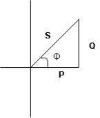
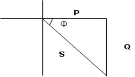
 Power triangle
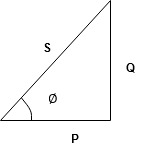
- As we know power factor is cosine of angle between voltage and current
i e P.F. = Cos
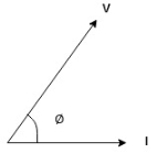
In other words also we can derive it from impedance triangle
Now consider Impedance triangle in R – L- ckt.
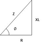
From  now Cos
  = power factor =
 power factor = Cos
  or
or 
3.13.2. Significance of Power Factor
The term power factor is defined in three ways-
- “The cosine of an angle between current and voltage of an Ac circuit is called power factor”
- “The ratio between the resistance and total impedance of an Ac circuit is called power factor”
- “The ratio between the active power and apparent power is called power factor”
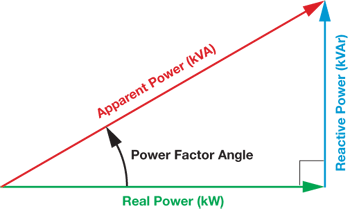
Considering an inductive load, the power factor will be lagging due to which the current is lagging behind the voltage. While in capacitive load the angle goes opposite, the applied current angle is now leading before the voltage and consider as leading power factor.
The power factor plays an important role in ac circuits depending upon the load. The lower the power factor, higher is the load current and vice-versa.