Unit 4
Three phase A.C. Circuits
The advantages of 3 phase system are –
- Power delivered is constant.
- For a given frame size a 3 phase machine gives a higher output.
- 3 phase induction motors are self starting and are more efficient.
- Three phase induction motor has higher power factor and efficiency.
Three phase motors are very robust, relatively cheap, generally smaller, have self-starting properties, provide a steadier output and require little maintenance compared with single phase motors.
- For transmitting the same amount of power at the same voltage, a three phase transmission line requires less conductor material. The three phase transmission system is cheaper.
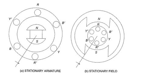
The three -phase voltage can be generated in stationary armature with rotating field structure or in rotating armature with a stationary field as shown in figure.
Single phase voltages and currents are generated by single phase generators as shown in Figure. The armature of such a generator has only one winding, or one set of coils. In a two-phase generator the armature has two distinct windings, or two sets of coils that are displaced 90° apart, so that the generated voltages in the two phases have 90 degrees phase displacement as shown in Fig. b.
For Three Phase Voltage are generated in three separate but identical sets of windings or coils that are displaced by 120 electrical degrees in the armature, so that the voltages generated in them are 120° apart in time phase. This arrangement is shown in Fig. (c). Here RR’ constitutes one coil (R-phase); YY’ another coil (Y-phase), and BB’ constitutes the third phase (B-phase). The field magnets are assumed in clockwise rotation.
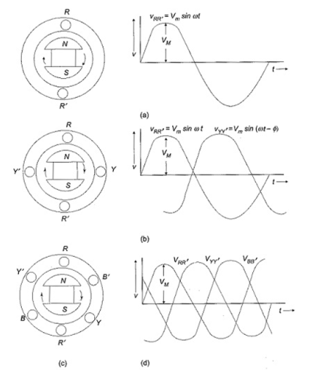
The voltages generated by a three-phase alternator is shown in Fig. (d). The Three Phase voltage are of the same magnitude and frequency; but are displaced from one another by 120°. Assuming the voltages to be sinusoidal, we can write the equations for the instantaneous values of the voltages of the three phases. Counting the time from the instant when the voltage in phase R is zero. The equations are
v RR’ = Vmsinwt
v YY’ = Vm sin (wt -120 o )
v BB’ = Vm sin(wt -240 o )
At any given instant, the algebraic sum of the three voltages must be zero.
Phase Sequence:
Here the sequence of voltages in the three phases are in the order υRR′ – υYY′ – υBB′, and they undergo changes one after the other in the mentioned order. This is called the phase sequence. This sequence depends on the rotation of the field. If the field system is rotated in anticlockwise direction, then the sequence of the voltages in the three-phases are in the order υRR′ – υBB′ – υYY′. Now the equations can be written as
v RR’ = Vmsinwt
v BB’ = Vm sin (wt -120)
v YY’ = Vm sin(wt – 240)
Balanced load : balanced load is that in which magnitude of all impedance connected in the load are equal and the phase angle of them are also equal
Ie Z1 Z2
Z2  Z3 then it is unbalanced load
Connected circuit and delta connected circuit.
4.4.1. Relation between line and phase quantities for star
Connected circuit-
The relations between line and phase currents and voltages of a star connected system, we first draw a balanced star connected system.
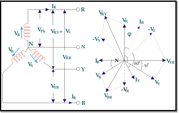

Suppose due to load impedance the current lags the applied voltage in each phase of the system by an angle ϕ. As the system is perfectly balanced, the magnitude of current and voltage of each phase is the same. Let us say, the magnitude of the voltage across the red phase i.e. magnitude of the voltage between neutral point (N) and red phase terminal (R) is VR.
Similarly, the magnitude of the voltage across yellow phase is VY and the magnitude of the voltage across blue phase is VB.
In the balanced star system, magnitude of phase voltage in each phase is Vph.
∴ VR = VY = VB = Vph
In the star connection, line current is same as phase current. The magnitude of this current is same in all three phases and say it is IL.
∴ IR = IY = IB = IL, Where, IR is line current of R phase, IY is line current of Y phase and IB is line current of B phase. Again, phase current, Iph of each phase is same as line current IL in star connected system.
∴ IR = IY = IB = IL = Iph.
Now, let us say, the voltage across R and Y terminal of the star connected circuit is VRY.
The voltage across Y and B terminal of the star connected circuit is VYBBR.
From the diagram, it is found that
VRY = VR + (− VY)
Similarly, VYB = VY + (− VB)
And, VBR = VB + (− VR)
Now, as angle between VR and VY is 120o(electrical), the angle between VR and – VY is 180o – 120o = 60o(electrical).
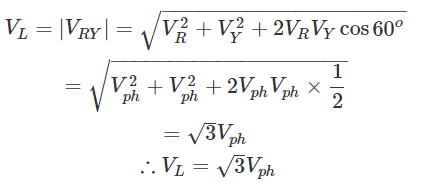

Thus, for the star-connected system line voltage = √3 × phase voltage.
Line current = Phase current
As, the angle between voltage and current per phase is φ, the electric power per phase is


So the total power of three phase system is-


4.4.2. Relation between line and phase quantities for delta
Connected circuit-
To understand the relation between line voltage and phase voltage quantities, let us draw a figure.
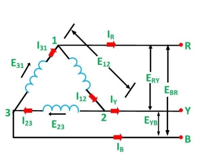
From the figure 1, it is clear that , the voltage across terminals 1 and 2 is the same as across the terminals R and Y. Therefore,
E12 = ERY
Similarly,

The phase voltages are-

The line voltages are:

Hence, in delta connection line voltage is equal to phase voltage.
For relation between phase current and line current in delta connection-
As in the balanced system the three-phase current I12, I23 and I31 are equal in magnitude but are displaced from one another by 120° electrical.
The phasor diagram is drawn below:
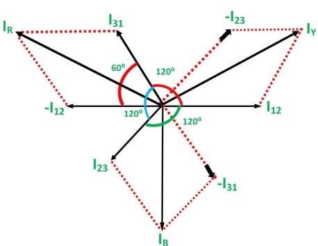
Hence,

If we look at figure 1, it is seen that the current is divided at every junction 1, 2 and 3.
Applying Kirchhoff’s Law at junction 1,
The Incoming currents are equal to outgoing currents.

And their vector difference will be given as:

The vector I12 is reversed and is added in the vector I31 to get the vector sum of I31 and –I12 as shown above in the phasor diagram. Therefore,
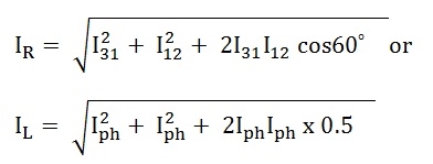
As we know, IR = IL, therefore,

Similarly,

Hence, in delta connection line current is root three times of phase current.
