UNIT 2
INTRODUCTION TO I.C ENGINE
A Carnot engine or Carnot heat engine is an idealised engine whose working is perfectly reversible. This engine uses an ideal gas as the working substance and performs a 4-stroke process to complete one cycle.
It takes heat Q1 from source and rejects heat Q2 to sink and performing an amount of work W=Q1−Q2
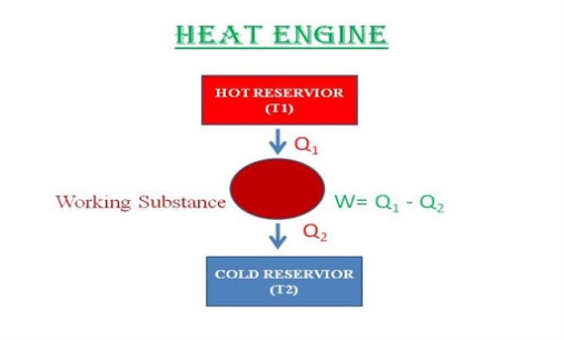
The Carnot's engine is a reversible engine working between two temperature limits.
The complete cycle functions are given below
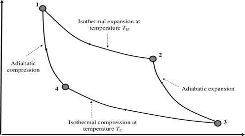
1) Reversible Isothermal expansion heat addition at the constant temperature T1 or TH
2) Reversible Adiabatic expansion of ideal gas. In this process, the temperature of the ideal gas falls from source temperature T1 to sink temperature T2.
3) Reversible Isothermal compression of ideal gas at sink temperature T2 or TC. In doing so, it rejects heat Q2 to the sink.
4) Reversible Adiabatic compression of ideal gas where the temperature naturally raises from T2 to T1 and thus the working substance returns to its original state completing the cycle.
The efficiency is given as
η= Work done / Heat input
Thus, W=Q1−Q2 and heat input is obviously Q1
This gives, η= W/Q1
=1−Q2/Q1
It may be shown thermodynamically that Q2/Q1 = T2/T1.
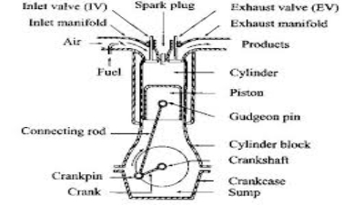
An I.C engine consists of a cylinder and piston. Piston is connected to the crank-shaft through connecting Rod. At the head of the cylinder intake valve and exhaust valve is present that are operated by a camshaft.
For SI engine a spark plug is present and for CI engine a fuel spray nozzle is present. Cooling system (water jacket) is provided outside the cylinder. Lubricant-oil system is provided along with the piston. There are some piston rings to avoid wear and tear of the cylinder and piston.
For two stroke engine valves are eliminated by ports. There are some accessories with the engine like carburettor, injection system, cooling system, lub oil system, catalytic converter, and many others.
S.I Engine: S I Stands for Spark Ignition. This is one kind of IC (Internal Combustion) engine.
There are four processes in engine.
- Intake or suction
- Compression
- Power or combustion
- Exhaust


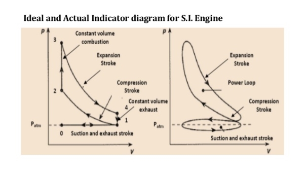
Process 0-1 (Suction stroke)
At the start of cycle the piston moves from TDC to BDC. The inlet valve (I.V.) is opened automatically by valve operating mechanism at the start of this process. Due to increase in volume inside the cylinder, a slight vacuum is created and, the fresh charge i.e. mixture of air and petrol prepared in Carburettor is sucked inside the cylinder through inlet valve. At the end of stroke, the piston reaches BDC position, total volume of cylinder is filled with fresh charge and inlet valve is closed. Theoretically, the charge is filled at constant pressure P1 and it occupies the total volume of cylinder V1.
Process 1-2 (Compression stroke)
During this stroke, both the valves remain closed and piston is moved from BDC to TDC by the force of crank. As the piston moves up, volume of cylinder shrinks and the fresh charge is compressed to a higher pressure P2 and volume V2 equal to clearance volume. Theoretically, this process is adiabatic compression process. Temperature of fresh charge is also raised in compression from T1 to T2.
Process 2-3 (heat addition or constant volume combustion)
This process is actually a constant volume heat addition process. At point 2, spark plug ignites and starts the combustion of already compressed, high temperature charge. Due to very favourable conditions of combustion, combustion of charge and heat release takes place in no time and pressure & temperature further shoots up to P3 and T3. Theoretically the volume remains constant from 2 to 3. So V2=V3=VC=Clearance Volume.
Process 3-4 (expansion or working stroke)
This is the process or stroke of piston in which positive work is obtained. The burnt gases at high pressure and high temperature at point 3 expand and push the piston again from TDC to BDC, thus doing work on the piston. This work is given to output shaft of engine through connecting rod and crank shaft. A small portion of it is stored in the heavy rotating flywheel mounted on crankshaft, which is used in movement of piston in three other idle stroke i.e. Suction, Compression and Exhaust. When piston reaches BDC, cylindrical total volume is filled with comparatively lower pressure and temperature burnt gases or smoke. At this point 4, the exhaust valve (EV) opens.
Process 4-1 (heat rejection or constant volume exhaust)
In this process, as soon as the exhaust valve is opened at point 4, the burnt gases start escaping to atmosphere and their pressure reduces to atmospheric pressure P1. Theoretically, this process happens in no time and escaping of exhaust gases take away some heat from the engine.
Process 1-0 (exhaust stroke)
This stroke is just opposite to suction stroke. Piston moves from BDC to TDC and pushes away or sweeps the remaining burnt gases out through E.V. As the piston reaches TDC most of burnt gases escape and E.V. Is closed. One cycle of the engine completes here. Simultaneously, the I.V. Opens and next cycle starts.
In this way, piston goes on moving or reciprocating from TDC to BDC and BDC to TDC with a high speed and engine produces power continuously by burning of petrol or gas etc. The power output and RPM of engine can be easily controlled by a throttling valve fitted in the passage of air intake or in the carburettor where fuel and air are mixed together in the right proportion..
In the exhaust phase, The piston goes upward and the burnt gases go away through the exhaust valve.
C.I Engine: A diesel engine is called compression Ignition engine because here the conditions of combustion or ignition are achieved only by compression of air to a very high pressure.
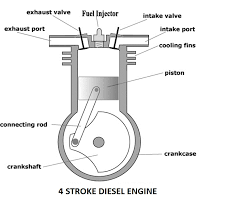
There is no spark plug to initiate the combustion, but in place of that a fuel injector is there, which injects and atomizes the fuel. Diesel at a very high pressure in very hot compressed air after compression stroke in engine. Due to high pressure and temperature above the ignition temperature, fuel atomization, evaporation and self-ignition take place.
The rest of the working of Diesel Engine is same as that of Petrol or Gasoline Engine. Here also one complete cycle is comprised of all the processes of Diesel cycle along with suction of fresh air and exhaust of burnt gases. To carry out all these processes, here also normally 4 strokes of piston are required. So, it is called a 4-stroke Diesel Engine or C.I Engine.

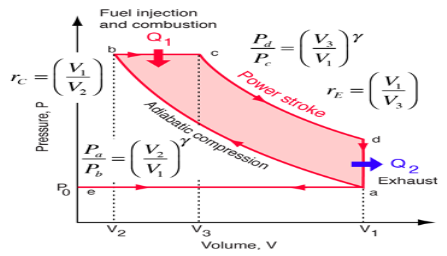
Process e-a (suction stroke)
At the start of cycle, the piston moves from TDC to BDC and inlet valve is opened at the start of process at point e. Due to increase in volume of cylinder by the movement of piston, the fresh air from atmosphere enters the cylinder and occupies all the space inside the cylinder until piston reaches BDC. At the point a, air filled in cylinder is at volume V1 and its pressure & temperature are theoretically same as that of outside atmosphere. Here inlet valve is closed and cylinder becomes a closed thermodynamic system.
Process a-b (compression stroke)
In this stroke, piston moves from BDC to TDC by the force of crank. As both valves are closed, the air sucked in previous stroke is compressed to the clearance volume. Here in Diesel engine the compression ratio rc which is the ratio of total volume V1 to clearance volume V2 is very high as compared to SI Engine. So, naturally the rise in pressure and temperature of air at the end of compression stroke is also more. The range of rc (compression ratio) in Diesel Engine is 15 to 22. Theoretically, the compression process is adiabatic & isentropic Compression.
Process b-c (heat addition or fuel injector)
This process is actually a constant pressure heat addition process or a mix of constant volume and constant pressure process as in case of high speed diesel engine. At the point b the fuel injector injects a fix quantity of fuel in very hot & compressed air compressed to the clearance volume. Due to that fuel spray ignites itself thus releasing of heat in the cylinder. As this heat addition process is slow, piston moves back to some distance from TDC to point c shown in fig and the volume increases which nullifies the effect of increase in pressure due to heat addition. Pressure remains constant theoretically upto point c, where the injector stops injection of fuel and so the addition of heat. Point c is also called cut-off point. A part of piston stroke from b to c takes place along with this process and the burning fuel plus air mixture expand and push the piston producing a positive work.
Process c-d (expansion stroke or power stroke)
Actually the complete expansion stroke is from point b to point d but a part of it is along the previous heat addition process b-c. After point c heat addition stops and the hot and high pressure burnt gases expand at the cost of their own internal energy and produce positive work by pushing the piston to BDC. This stroke is called working stroke as here piston moves the crankshaft and give mechanical energy. Major part of this energy is given to output shaft and a small portion is stored in heavy flywheel in the form of its rotational kinetic energy and used up during idle strokes of piston i.e. Suction, Compression & Exhaust.
Process d-a (heat rejection )
This process takes place at constant volume and heat is rejected directly by escaping of some of burnt gases due to pressure difference inside and outside the engine as soon as exhaust valve opens at point d i.e. just at the end of expansion or working stroke. Theoretically, piston remains at BDC and gases escape in no time, taking away some heat from the engine. Pressure inside the cylinder reduces to atmospheric pressure.
Process a-e (exhaust stroke)
In this process or stroke, piston is moved by crank from BDC to TDC. As the exhaust valve remains open during this stroke, piston displaces or sweeps out the burnt gases through it and only a small fraction of gases remain in the clearance volume finally. The piston reaches TDC and the cycle completes as the initial conditions are again reached. At this point, exhaust valve closes and inlet valve opens and next cycle starts.
In this way piston moves or reciprocates from TDC to BDC and again from BDC to TDC with a high speed and engine produces power continuously by burning of air and fuel mixture. The power output and RPM of engine here can be controlled by controlling the quantity of fuel injected only. There is no restriction on the quantity of air sucked by engine. There is a mechanical or electric control on the fuel injection depending on fuel injection system used. When more power is required more quantity of fuel is injected and when less power is required accordingly fuel supply is reduced. There is no control on the quantity of air so air sucked remains more or less same. In this way only the quality of combustible mixture changes in different conditions of loading and so Quality Governing is used in CI Engine.
In two stroke engine the working cycle is completed in two stroke of the piston or one revolution of crankshaft. This is achieved by carried out suction and compression in one stroke expansion and exhaust in the second stroke.
A two stroke engine has port instead of valves. Opening and closing of the port are controlled by the piston
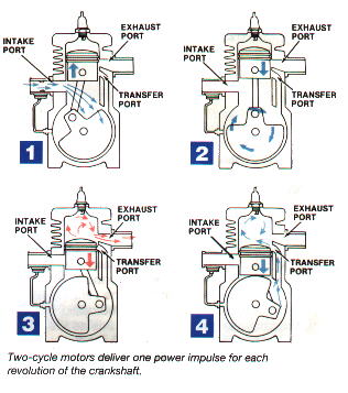
Following are the process in two stroke engine
1) Suction stroke: In this stroke piston while moving downward BDC (bottom dead centre) both the transfer port and exhaust port are open. The fresh fuel air mixture flows into the engine cylinder from crankcase.
2) Compression stroke: In this stroke, the piston while moving upwards, first cover the transfer port then exhausts port. After that fuel is compressed as the piston moves upwards. In this stage the inlet port opens and fresh air fuel mixture enters into crankcase.
3) Expansion stroke: During compression stroke the piston reached TDC (top dead centre) the charge is ignited with the help of spark plug .It suddenly increases the pressure and temperature of the product of combustion and volume remain constant. Due to rise in pressure the piston is pushed downwards with greater pressure .During the expansion some of the heat energy is produces and transform into mechanical work.
4) Exhaust stroke: In this stroke piston move downward and exhaust port is opened. The burned gases are exhaust from the engine cylinder through exhaust port into the atmosphere.
The two-stroke engines lighter, simpler and less expensive to manufacture. Two-stroke engines also have the potential to pack about twice the power into the same space because there are twice as many power strokes per revolution. The combination of light weight and twice the power gives two-stroke engines a great power-to-weight ratio compared to many four-stroke engine designs.
In four stroke engine the working cycle is completed in four stroke of the piston or two revolution of crankshaft. This is achieved by carried out suction in one stroke and compression in second stroke, expansion in third stroke and exhaust in the fourth stroke. They have inlet and exhaust valve. Suction and compression in one revolution of crankshaft, expansion and exhaust in second revolution of crankshaft.
Following are the process in four stroke engine;
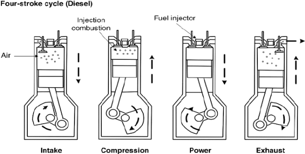
1) Suction stroke: In this stroke while piston moving downward BDC (bottom dead centre) inlet valve opens and pure air is sucked into the cylinder.
2) Compression stroke: In this stroke, the piston while moving from BDC to TDC, the inlet and outlet valve are closed. The compressed start as piston moves upwards. Which increase pressure and temperature .this complete one revolution of crankshaft
3) Expansion stroke: just before the piston reached the top dead centre fuel oil injected in the form of very fine spray into the cylinder . At this point temperature of the compressed air is sufficiently high to ignite the fuel which suddenly increase the pressure and temperature of combustion products. Due to increase in pressure the piston is pushed down with a great force.
4) Exhaust stroke: In this stroke exhaust valve open as piston move from BDC to TDC .This movement of the piston moves up and pushed out the burned gases to atmosphere from the engine cylinder
CARNOT CYCLE: In a Carnot cycle, the working substance is subjected to a cyclic operation consisting of two isothermal and two adiabatic processes. The engine developed by Carnot has air (which is assumed to work as a perfect gas) as its working substance enclosed in a cylinder, in which a frictionless piston moves.
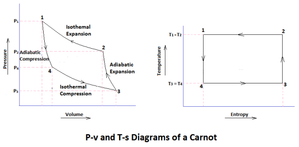
Carnot Cycle Processes
- Isothermal Expansion
- Adiabatic or Isentropic Expansion
- Isothermal Compression
- Isentropic Compression
Process 1-2 (Isothermal Expansion)
- The source (hot body, H.B) at a higher temperature is brought in contact with the bottom B of the cylinder.
- The air expands, practically at constant temperature T1, from v1 to v2.
- It means that the temperature T2 (at point 2) equals to the temperature T1.
- This isothermal expansion is represented by curve 1-2 on p-v and T-s diagrams in the figure.
- The heat supplied the hot body is fully absorbed by the air and is utilized in doing external work.
Heat supplied = Work done during isothermal expansion
H1= p1v1 ln (v2/v1) = m R T1 ln (v2/v1)
Process 2-3 (Adiabatic or Isentropic Expansion)
- The hot body is removed from the bottom of the cylinder B and the insulating cap I.C. Is brought in contact.
- The air is now allowed to expand adiabatically. Thus adiabatic expansion is represented by the curve 2-3 on p-v and T-s diagrams.
- The temperature of the air decreases from T2 to T3.
- Since no heat is absorbed or rejected by the air, therefore decreases in internal energy.
Work done = W 2-3 = mcv (T1-T2)
Process 3-4 (Isothermal Compression)
- Now remove the insulating cap I.C. From the bottom of the cylinder and bring the cold body CB in its contact.
- The air is compressed practically at a constant temperature T3 from V3 to V4.
- It means that the temperature T4 ( at point 4) is equal to the temperature T3.
- This isothermal compression is represented by the curve 3-4 on P-V and T-s diagram.
- It would be seen that during this process, the heat is rejected to the cold body and is equal to the work done on the air.
Hear rejected = Work done on the air
W3-4 =-p3v3 ln (v3/v4)
= -m R T2 ln (v3/v4)
Process 4-1 (Isentropic Compression)
- Now again the insulated cap I.C. Is brought in contact with the bottom of the cylinder B, and the air is allowed to be compressed adiabatically.
- The adiabatic compression is represented by the curve 4-1 on p-v and T-s diagram.
- The temperature of the air increases from T4 to T1. Since no heat is absorbed or rejected by the air, therefore
Increases in internal energy = Work done on the air
W4-1 = -m cv (T1-T2)
We know that efficiency =work done/ heat supply
η= W/Q1
Net work per cycle = area 1-2-3-4
W = m R T1 ln (v2/v1) + mcv (T1-T2) -m R T2 ln (v3/v4) -m cv (T1-T2)
W = m R T1 ln (v2/v1) -m R T2 ln (v3/v4)
Heat supply = work done + change in internal energy
Q = W1-2 +U2-U1
There is no change in internal energy U1=U2
Q=W1-2 = m R T1 ln (v2/v1)
η= W / Q1 = m R T1 ln (v2/v1) -m R T2 ln (v3/v4) / m R T1 ln (v2/v1)
= T1 ln (v2/v1) - T2 ln (v3/v4) / T1 ln (v2/v1)
We know that (v2/v1) = (v3/v4) eliminate these terms
We get
η= W / Q1 = T1 - T2 / T1
η= 1- T2 / T1
JOULE CYCLE: Brayton cycle (or Joule Cycle) is a thermodynamic cycle upon which a Gas turbine works. Gas turbines are used to generate power at many places. Brayton cycle is named after George Brayton, an American engineer who developed it.
Below are P-V and T-S Diagrams of the Brayton (or Joule) Cycle 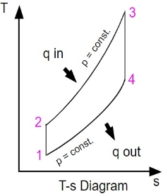
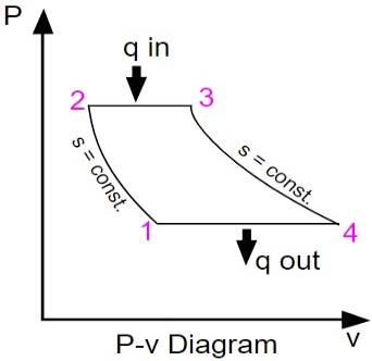
Brayton Cycle is comprised of four processes:
Process 1-2: It is isentropic compression process. Here a little rise in the temperature of gas occurs due to compression. Since it is a compression process, volume of the gas decreases.
Change in internal energy = CV (T2-T1)
Work Interaction = (h2-h1)
Heat Interaction = 0
Process 2-3: It is isobaric heat addition process. A little increase in volume happens due to heat addition. Since it is a heat addition process, temperature of the gas increases.
Change in internal energy = CV(T3-T2)
Work Interaction = 0
Heat Interaction = (h3-h2)
Process 3-4: It is isentropic expansion process. Here a little dip in temperature occurs due to expansion. Since it is an expansion process, volume of the gas increases.
Change in internal energy = CV (T4-T3)
Work Interaction = (h3-h4)
Heat Interaction = 0
Process 4-1 :It is isobaric heat rejection process. A little decrease in volume happens due to heat rejection. Since it is a heat rejection process, temperature of the gas decreases.
Change in internal energy = CV(T1-T4)
Work Interaction = 0
Heat Interaction = (h4-h1)
Efficiency
Work output = [(h3-h2) – (h4-h1)]
Heat Input = (h3-h2)
Efficiency = Work Output/Heat Input
After putting values of heat input and work output in the above formula,
We get
η = 1 – [(h4-h1)/ (h3-h2)]
Also
η = 1 – [(T4-T1)/ (T3-T2)]
OTTO CYCLE: Otto cycle is a thermodynamic cycle upon which a spark ignition engine works. Spark Ignition (or SI) engine uses petrol (or Gasoline) as fuel. Otto cycle was invented by Nicolas Otto in 1876.
Spark ignition engine is a type of internal combustion engines.
Below are P-V and T-S Diagrams of the Otto Cycle.
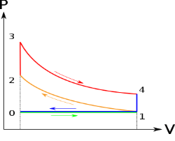
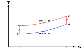
Otto Cycle is comprised of four processes (apart from the intake and exhaust process)
Process 1-2: This process comes after intake process. In case of SI engines, intake is a mixture of gasoline and air, also known as charge. In this process charge is compressed in isentropic manner. Temperature raised from T1 to T2 and volume decrease from V1 to V2.
Process 2-3: In this process the fuel gets blasted with the help of external spark (that is why the engine is known as spark ignition engine). This process is a constant volume heat addition process. Temperature raised from T2 to T3
.
Q2-3= CV(T3-T2)
Process 3-4: After the combustion process, the exhaust gases expend. This process is an isentropic expansion process. No heat is interchanged. The temperature fall from T3 to T4 and volume increase from V3 to V4.
Process 4-1: After the expansion process, exhaust valve opens. This results into sudden drop of pressure inside engine cylinder. This process is a constant volume heat rejection process.
Q4-1= CV(T4-T1)
Process 0-1 is the intake process and process 1-0 is the exhaust process.
Efficiency of the Otto Cycle is the ratio of work output to the heat input.
Work done or output = Heat supply-Heat rejected
Work output = [CV (T3-T2)] – [CV (T4-T1)]
Heat Input = CV (T3-T2)
Efficiency = Work done / Heat Input
After putting values of heat input and work output in the above formula, we get
η = [CV (T3-T2)] – [CV (T4-T1)] / CV (T3-T2)
η = 1 – [(T4-T1)/ (T3-T2)]
η = 1 – [T1 (T4 / T1 – 1 )/ T2 (T3/T2 - 1)]
r = compression ratio = V1 / V2 = V4 / V3
T2 = T1 (V1/V2) y-1
T2 = T1 (r) y-1 ……..equation 1
T3/T4 = (V4 /V3)y-1
T3 = T4 (r) y-1 ……equation 2
From equation 1 and 2
T2 / T1 = T3/T4
Or T4 / T1 = T3 / T2
Put the value in this equation
η = 1 – [T1 (T4 / T1 – 1)/ T2 (T3/T2 - 1)]
We get
η = 1 – [T1 / T2]
Or η = 1 – 1 / (r )y-1