Unit 6
Computer Programming
Program Development Life Cycle (PDLC) is a systematic way of developing quality software. It provides an organized plan for breaking down the task of program development into manageable chunks, each of which must be successfully completed before moving on to the next phase.
The program development process is divided into the steps discussed below:
- Defining the Problem –
The first step is to define the problem. In major software projects, this is a job for system analyst, who provides the results of their work to programmers in the form of a program specification. The program specification defines the data used in program, the processing that should take place while finding a solution, the format of the output and the user interface.
2. Designing the Program –
Program design starts by focusing on the main goal that the program is trying to achieve and then breaking the program into manageable components, each of which contributes to this goal. This approach of program design is called top-bottom program design or modular programming. The first step involve identifying main routine, which is the one of program’s major activity. From that point, programmers try to divide the various components of the main routine into smaller parts called modules. For each module, programmer draws a conceptual plan using an appropriate program design tool to visualize how the module will do its assign job.
Program Design Tools:
The various program design tools are described below:
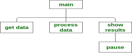
- Structure Charts – A structure chart, also called Hierarchy chart, show top-down design of program. Each box in the structure chart indicates a task that program must accomplish. The Top module, called the Main module or Control module. For example:
- Algorithms –
An algorithm is a step-by-step description of how to arrive at a solution in the most easiest way. Algorithms are not restricted to computer world only. In fact, we use them in everyday life. - Flowcharts –
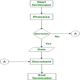
A flowchart is a diagram that shows the logic of the program. For example:
- Decision tables –
A Decision table is a special kind of table, which is divided into four parts by a pair of horizontal and vertical lines. - Pseudocode –
A pseudocode is another tool to describe the way to arrive at a solution. They are different from algorithm by the fact that they are expressed in program language like constructs.
3. Coding the Program –
Coding the program means translating an algorithm into specific programming language. The technique of programming using only well defined control structures is known as Structured programming. Programmer must follow the language rules, violation of any rule causes error. These errors must be eliminated before going to the next step.
4. Testing and Debugging the Program –
After removal of syntax errors, the program will execute. However, the output of the program may not be correct. This is because of logical error in the program. A logical error is a mistake that the programmer made while designing the solution to a problem. So the programmer must find and correct logical errors by carefully examining the program output using Test data. Syntax error and Logical error are collectively known as Bugs. The process of identifying errors and eliminating them is known as Debugging.
5. Documenting the Program –
After testing, the software project is almost complete. The structure charts, pseudocodes, flowcharts and decision tables developed during the design phase become documentation for others who are associated with the software project. This phase ends by writing a manual that provides an overview of the program’s functionality, tutorials for the beginner, in-depth explanations of major program features, reference documentation of all program commands and a thorough description of the error messages generated by the program.
6. Deploying and Maintaining the Program –
In the final phase, the program is deployed (installed) at the user’s site. Here also, the program is kept under watch till the user gives a green signal to it.
Even after the software is completed, it needs to be maintained and evaluated regularly. In software maintenance, the programming team fixes program errors and updates the software.
What is Algorithm? Algorithm Basics
The word Algorithm means “a process or set of rules to be followed in calculations or other problem-solving operations”. Therefore Algorithm refers to a set of rules/instructions that step-by-step define how a work is to be executed upon in order to get the expected results.
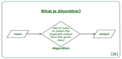
It can be understood by taking an example of cooking a new recipe. To cook a new recipe, one reads the instructions and steps and execute them one by one, in the given sequence. The result thus obtained is the new dish cooked perfectly. Similarly, algorithms help to do a task in programming to get the expected output.
The Algorithm designed are language-independent, i.e. they are just plain instructions that can be implemented in any language, and yet the output will be the same, as expected.
What are the Characteristics of an Algorithm?
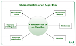
As one would not follow any written instructions to cook the recipe, but only the standard one. Similarly, not all written instructions for programming is an algorithm. In order for some instructions to be an algorithm, it must have the following characteristics:
- Clear and Unambiguous: Algorithm should be clear and unambiguous. Each of its steps should be clear in all aspects and must lead to only one meaning.
- Well-Defined Inputs: If an algorithm says to take inputs, it should be well-defined inputs.
- Well-Defined Outputs: The algorithm must clearly define what output will be yielded and it should be well-defined as well.
- Finite-ness: The algorithm must be finite, i.e. it should not end up in an infinite loops or similar.
- Feasible: The algorithm must be simple, generic and practical, such that it can be executed upon will the available resources. It must not contain some future technology, or anything.
- Language Independent: The Algorithm designed must be language-independent, i.e. it must be just plain instructions that can be implemented in any language, and yet the output will be same, as expected.
How to Design an Algorithm?
Inorder to write an algorithm, following things are needed as a pre-requisite:
- The problem that is to be solved by this algorithm.
- The constraints of the problem that must be considered while solving the problem.
- The input to be taken to solve the problem.
- The output to be expected when the problem the is solved.
- The solution to this problem, in the given constraints.
Then the algorithm is written with the help of above parameters such that it solves the problem.
Example: Consider the example to add three numbers and print the sum.
- Step 1: Fulfilling the pre-requisites
As discussed above, in order to write an algorithm, its pre-requisites must be fulfilled.
- The problem that is to be solved by this algorithm: Add 3 numbers and print their sum.
- The constraints of the problem that must be considered while solving the problem: The numbers must contain only digits and no other characters.
- The input to be taken to solve the problem: The three numbers to be added.
- The output to be expected when the problem the is solved: The sum of the three numbers taken as the input.
- The solution to this problem, in the given constraints: The solution consists of adding the 3 numbers. It can be done with the help of ‘+’ operator, or bit-wise, or any other method.
- Step 2: Designing the algorithm
Now let’s design the algorithm with the help of above pre-requisites:
Algorithm to add 3 numbers and print their sum:
- START
- Declare 3 integer variables num1, num2 and num3.
- Take the three numbers, to be added, as inputs in variables num1, num2, and num3 respectively.
- Declare an integer variable sum to store the resultant sum of the 3 numbers.
- Add the 3 numbers and store the result in the variable sum.
- Print the value of variable sum
- END
- Step 3: Testing the algorithm by implementing it.
Inorder to test the algorithm, let’s implement it in C language.
Program:
// C program to add three numbers // with the help of above designed algorithm
#include <stdio.h>
Int main() {
// Variables to take the input of the 3 numbers Int num1, num2, num3;
// Variable to store the resultant sum Int sum;
// Take the 3 numbers as input Printf("Enter the 1st number: "); Scanf("%d", &num1); Printf("%d\n", num1);
Printf("Enter the 2nd number: "); Scanf("%d", &num2); Printf("%d\n", num2);
Printf("Enter the 3rd number: "); Scanf("%d", &num3); Printf("%d\n", num3);
// Calculate the sum using + operator // and store it in variable sum Sum = num1 + num2 + num3;
// Print the sum Printf("\nSum of the 3 numbers is: %d", sum);
Return 0; } |
Output:
Enter the 1st number: 2
Enter the 2nd number: 3
Enter the 3rd number: 5
Sum of the 3 numbers is: 10
One problem, many solution: The solution to an algorithm can be or cannot be more than one. It means that while implementing the algorithm, there can be more than one method to do implement it. For example, in the above problem to add 3 numbers, the sum can be calculated with many ways like:
- + operator
- Bit-wise operators
- . . Etc
How to Analyse an Algorithm?
For a standard algorithm to be good, it must be efficient. Hence the efficiency of an algorithm must be checked and maintained. It can be in two stages:
4. Priori Analysis: “Priori” means “before”. Hence Priori analysis means checking the algorithm before its implementation. In this, the algorithm is checked when it is written in the form of theoretical steps. This Efficiency of an algorithm is measured by assuming that all other factors, for example, processor speed, are constant and have no effect on the implementation. This is done usually by the algorithm designer. It is in this method, that the Algorithm Complexity is determined.
5. Posterior Analysis: “Posterior” means “after”. Hence Posterior analysis means checking the algorithm after its implementation. In this, the algorithm is checked by implementing it in any programming language and executing it. This analysis helps to get the actual and real analysis report about correctness, space required, time consumed etc.
What is Algorithm Complexity and How to find it?
An algorithm is defined as complex based on the amount of Space and Time it consumes. Hence the Complexity of an algorithm refers to the measure of the Time that it will need to execute and get the expected output, and the Space it will need to store all the data (input, temporary data and output). Hence these two factors define the efficiency of an algorithm.
The two factors of Algorithm Complexity are:
- Time Factor: Time is measured by counting the number of key operations such as comparisons in the sorting algorithm.
- Space Factor: Space is measured by counting the maximum memory space required by the algorithm.
Therefore the complexity of an algorithm can be divided into two types:
8. Space Complexity: Space complexity of an algorithm refers to the amount of memory that this algorithm requires to execute and get the result. This can be for inputs, temporary operations, or outputs.
How to calculate Space Complexity?
The space complexity of an algorithm is calculated by determining following 2 components:
- Fixed Part: This refers to the space that is definitely required by the algorithm. For example, input variables, output variables, program size, etc.
- Variable Part: This refers to the space that can be different based on the implementation of the algorithm. For example, temporary variables, dynamic memory allocation, recursion stack space, etc.
Therefore Space complexity  of any algorithm P is
  , where C is the fixed part and S(I) is the variable part of the algorithm, which depends on instance characteristic I.
Example: Consider the below algorithm for Linear Search
Step 1: START
Step 2: Get the array in arr and the number to be searched in x
Step 3: Start from the leftmost element of arr[] and one by one compare x with each element of arr[]
Step 4: If x matches with an element, Print True.
Step 5: If x doesn’t match with any of elements, Print False.
Step 6: END
Here, There are 2 variables arr, and x, where the arr is variable part and x is fixed part. Hence S(P) = 1+1. Now, space depends on data types of given variables and constant types and it will be multiplied accordingly.
9. Time Complexity: Time complexity of an algorithm refers to the amount of time that this algorithm requires to execute and get the result. This can be for normal operations, conditional if-else statements, loop statements, etc.
How to calculate Time Complexity?
The time complexity of an algorithm is also calculated by determining following 2 components:
- Constant time part: Any instruction that is executed just once comes in this part. For example, input, output, if-else, switch, etc.
- Variable Time Part: Any instruction that is executed more than once, say n times, comes in this part. For example, loops, recursion, etc.
Therefore Time complexity of any algorithm P is , where C is the constant time part and TP(I) is the variable part of the algorithm, which depends on instance characteristic I.
Example: In the algorithm of Linear Search above, the time complexity is calculated as follows:
Step 1: --Constant Time
Step 2: --Constant Time
Step 3: --Variable Time (Till the length of the Array, say n, or the index of the found element)
Step 4: --Constant Time
Step 5: --Constant Time
Step 6: --Constant Time
Hence, T(P) = 5 + n, which can be said as T(n).
What is a Flowchart?
Flowchart is a graphical representation of an algorithm. Programmers often use it as a program-planning tool to solve a problem. It makes use of symbols which are connected among them to indicate the flow of information and processing.
The process of drawing a flowchart for an algorithm is known as “flowcharting”.
Basic Symbols used in Flowchart Designs
- Terminal: The oval symbol indicates Start, Stop and Halt in a program’s logic flow. A pause/halt is generally used in a program logic under some error conditions. Terminal is the first and last symbols in the flowchart.

- Input/Output: A parallelogram denotes any function of input/output type. Program instructions that take input from input devices and display output on output devices are indicated with parallelogram in a flowchart.

- Processing: A box represents arithmetic instructions. All arithmetic processes such as adding, subtracting, multiplication and division are indicated by action or process symbol.

- Decision Diamond symbol represents a decision point. Decision based operations such as yes/no question or true/false are indicated by diamond in flowchart.

- Connectors: Whenever flowchart becomes complex or it spreads over more than one page, it is useful to use connectors to avoid any confusions. It is represented by a circle.

- Flow lines: Flow lines indicate the exact sequence in which instructions are executed. Arrows represent the direction of flow of control and relationship among different symbols of flowchart.
Example : Draw a flowchart to input two numbers from user and display the largest of two numbers
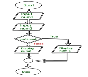
// C program to find largest of two numbers
#include <stdio.h>
Int main() { Int num1, num2, largest;
/*Input two numbers*/ Printf("Enter two numbers:\n"); Scanf("%d%d", &num1, &num2);
/*check if a is greater than b*/ If (num1 > num2) Largest = num1; Else Largest = num2;
/*Print the largest number*/ Printf("%d", largest);
Return 0; } |
Output
Enter two numbers:
10 0
30
And Repetition.
Structured Programming
Background
Since the invention by Von Neumann of the stored program computer, computer scientists have known that a tremendous power of computing equipment was the ability to alter its behavior, depending on the input data. Calculating machines had, for some time, been able to perform fixed arithmetic operations on data, but the potential of machines capable of making decisions opened up many new possibilities. Machines that could make decisions were capable of sorting records, tabulating and summarizing data, searching for information, and many more advanced operations that could not even be imagined at the time.
In early programming languages, like Fortran (first invented in 1954) and various low level machine languages, the goto statement allowed the computer to deviate from the sequential execution of the program instructions. The goto statement was recognized to be a very powerful construction, and soon, programs of increasing complexity and power were developed.
However, the increasingly complex code that resulted from goto statements became harder and harder to maintain. Dijkstra, in 1966, was one of the first persons to recognize that this run away complexity of programs was due to the overuse of the goto statement (Dijkstra, E. W., "Go To Considered Harmful," Communications of the ACM, March 1966). In fact, it was determined shortly thereafter, that the goto statement is not needed at all. Dijkstra showed that any program construction that could be created with goto statements could be created more simply with the sequence, repetition and decision constructions that are discussed in the following sections. This was the birth of the discipline of Structured Programming.
Structured Programming in Everyday Life
1. Sequence Execute a list of statements in order.
Example: Baking Bread
Add flour.
Add salt.
Add yeast.
Mix.
Add water.
Knead.
Let rise.
Bake.
2. Repetition Repeat a block of statements while a condition is true.
Example: Washing Dishes
Stack dishes by sink.
Fill sink with hot soapy water.
While moreDishes
Get dish from counter,
Wash dish,
Put dish in drain rack.
End While
Wipe off counter.
Rinse out sink.
3. Selection Choose at most one action from several alternative conditions.
Example: Sorting Mail
Get mail from mailbox.
Put mail on table.
While moreMailToSort
Get piece of mail from table.
If pieceIsPersonal Then
Read it.
ElseIf pieceIsMagazine Then
Put in magazine rack.
ElseIf pieceIsBill Then
Pay it,
ElseIf pieceIsJunkMail Then
Throw in wastebasket.
End If
End While
Structured Programming in Visual Basic
Structured programming is a program written with only the structured programming constructions: (1) sequence, (2) repetition, and (3) selection.
- Sequence. Lines or blocks of code are written and executed in sequential order.
Example:
x = 5
y = 11
z = x + y
WriteLine(z)
2. Repetition. Repeat a block of code (Action) while a condition is true. There is no limit to the number of times that the block can be executed.
While condition
action
End While
Example:
x = 2
While x < 100
WriteLine(x)
x = x * x
End
3. Selection. Execute a block of code (Action) if a condition is true. The block of code is executed at most once.
If condition Then
action
End If
Example:
x = ReadLine()
If x Mod 2 = 0
WriteLine("The number is even.")
End If
Extensions to Structured Programming
To make programs easier to read, some additional constructs were added to the basic three original structured programming constructs:
- Definite Repetition (For Loop) Combine initialization, checking a condition, and incrementing a counter in a single statement called a for statement. Here is the general form:
For i = 1 To n Step k ' Step k is optional
action
Next
Example:
For i = 1 To 20
WriteLine(i)
Next i
Example:
For i = 20 To 1 Step -1
WriteLine(i)
Next
2. If-Then-Else Statements Execute the first action whose corresponding condition is true. Here is the general form:
If condition1 Then
action1
ElseIf condition2 Then
action2
ElseIf condition3 Then
action3
Else
defaultAction
End If
Example:
If n = 1 Then
WriteLine("One")
ElseIf n = 2 Then
WriteLine("Two")
ElseIf n = 3 Then
WriteLine("Three")
Else
WriteLine("Many")
End If
3. Select Statement Execute the action corresponding to the value of the expression.
Select Case value1
Case value1
action1
Case value2
action2
Case value3
action3
Case Else
defaultAction
End Select
Example:
Select Case n
Case 1
WriteLine("One")
Case 2
WriteLine("Two")
Case 3
WriteLine("Three")
Case Else
WriteLine("Many")
End Select
Introduction to Computer Networks:
Computer Network
A computer network is a group of computers linked to each other that enables the computer to communicate with another computer and share their resources, data, and applications.
A computer network can be categorized by their size. A computer network is mainly of four types:
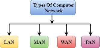
- LAN(Local Area Network)
- PAN(Personal Area Network)
- MAN(Metropolitan Area Network)
- WAN(Wide Area Network)
LAN(Local Area Network)
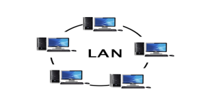
- Local Area Network is a group of computers connected to each other in a small area such as building, office.
- LAN is used for connecting two or more personal computers through a communication medium such as twisted pair, coaxial cable, etc.
- It is less costly as it is built with inexpensive hardware such as hubs, network adapters, and ethernet cables.
- The data is transferred at an extremely faster rate in Local Area Network.
- Local Area Network provides higher security.
PAN(Personal Area Network)
- Personal Area Network is a network arranged within an individual person, typically within a range of 10 meters.
- Personal Area Network is used for connecting the computer devices of personal use is known as Personal Area Network.
- Thomas Zimmerman was the first research scientist to bring the idea of the Personal Area Network.
- Personal Area Network covers an area of 30 feet.
- Personal computer devices that are used to develop the personal area network are the laptop, mobile phones, media player and play stations.
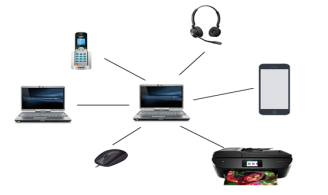
There are two types of Personal Area Network:
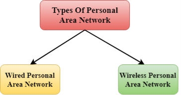
- Wired Personal Area Network
- Wireless Personal Area Network
Wireless Personal Area Network: Wireless Personal Area Network is developed by simply using wireless technologies such as WiFi, Bluetooth. It is a low range network.
Wired Personal Area Network: Wired Personal Area Network is created by using the USB.
Examples Of Personal Area Network:
- Body Area Network: Body Area Network is a network that moves with a person. For example, a mobile network moves with a person. Suppose a person establishes a network connection and then creates a connection with another device to share the information.
- Offline Network: An offline network can be created inside the home, so it is also known as a home network. A home network is designed to integrate the devices such as printers, computer, television but they are not connected to the internet.
- Small Home Office: It is used to connect a variety of devices to the internet and to a corporate network using a VPN
MAN(Metropolitan Area Network)
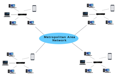
- A metropolitan area network is a network that covers a larger geographic area by interconnecting a different LAN to form a larger network.
- Government agencies use MAN to connect to the citizens and private industries.
- In MAN, various LANs are connected to each other through a telephone exchange line.
- The most widely used protocols in MAN are RS-232, Frame Relay, ATM, ISDN, OC-3, ADSL, etc.
- It has a higher range than Local Area Network(LAN).
Uses Of Metropolitan Area Network:
- MAN is used in communication between the banks in a city.
- It can be used in an Airline Reservation.
- It can be used in a college within a city.
- It can also be used for communication in the military.
WAN(Wide Area Network)
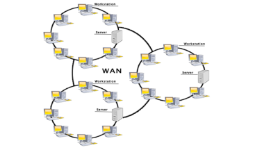
- A Wide Area Network is a network that extends over a large geographical area such as states or countries.
- A Wide Area Network is quite bigger network than the LAN.
- A Wide Area Network is not limited to a single location, but it spans over a large geographical area through a telephone line, fibre optic cable or satellite links.
- The internet is one of the biggest WAN in the world.
- A Wide Area Network is widely used in the field of Business, government, and education.
Examples Of Wide Area Network:
- Mobile Broadband: A 4G network is widely used across a region or country.
- Last mile: A telecom company is used to provide the internet services to the customers in hundreds of cities by connecting their home with fiber.
- Private network: A bank provides a private network that connects the 44 offices. This network is made by using the telephone leased line provided by the telecom company.
Advantages Of Wide Area Network:
Following are the advantages of the Wide Area Network:
- Geographical area: A Wide Area Network provides a large geographical area. Suppose if the branch of our office is in a different city then we can connect with them through WAN. The internet provides a leased line through which we can connect with another branch.
- Centralized data: In case of WAN network, data is centralized. Therefore, we do not need to buy the emails, files or back up servers.
- Get updated files: Software companies work on the live server. Therefore, the programmers get the updated files within seconds.
- Exchange messages: In a WAN network, messages are transmitted fast. The web application like Facebook, Whatsapp, Skype allows you to communicate with friends.
- Sharing of software and resources: In WAN network, we can share the software and other resources like a hard drive, RAM.
- Global business: We can do the business over the internet globally.
- High bandwidth: If we use the leased lines for our company then this gives the high bandwidth. The high bandwidth increases the data transfer rate which in turn increases the productivity of our company.
Disadvantages of Wide Area Network:
The following are the disadvantages of the Wide Area Network:
- Security issue: A WAN network has more security issues as compared to LAN and MAN network as all the technologies are combined together that creates the security problem.
- Needs Firewall & antivirus software: The data is transferred on the internet which can be changed or hacked by the hackers, so the firewall needs to be used. Some people can inject the virus in our system so antivirus is needed to protect from such a virus.
- High Setup cost: An installation cost of the WAN network is high as it involves the purchasing of routers, switches.
- Troubleshooting problems: It covers a large area so fixing the problem is difficult.
Internetwork
- An internetwork is defined as two or more computer network LANs or WAN or computer network segments are connected using devices, and they are configured by a local addressing scheme. This process is known as internetworking.
- An interconnection between public, private, commercial, industrial, or government computer networks can also be defined as internetworking.
- An internetworking uses the internet protocol.
- The reference model used for internetworking is Open System Interconnection(OSI).
Types Of Internetwork:
1. Extranet: An extranet is a communication network based on the internet protocol such as Transmission Control protocol and internet protocol. It is used for information sharing. The access to the extranet is restricted to only those users who have login credentials. An extranet is the lowest level of internetworking. It can be categorized as MAN, WAN or other computer networks. An extranet cannot have a single LAN, atleast it must have one connection to the external network.
2. Intranet: An intranet is a private network based on the internet protocol such as Transmission Control protocol and internet protocol. An intranet belongs to an organization which is only accessible by the organization's employee or members. The main aim of the intranet is to share the information and resources among the organization employees. An intranet provides the facility to work in groups and for teleconferences.
Intranet advantages:
- Communication: It provides a cheap and easy communication. An employee of the organization can communicate with another employee through email, chat.
- Time-saving: Information on the intranet is shared in real time, so it is time-saving.
- Collaboration: Collaboration is one of the most important advantage of the intranet. The information is distributed among the employees of the organization and can only be accessed by the authorized user.
- Platform independency: It is a neutral architecture as the computer can be connected to another device with different architecture.
- Cost effective: People can see the data and documents by using the browser and distributes the duplicate copies over the intranet. This leads to a reduction in the cost.
OSI Model
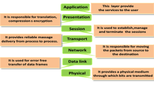
- OSI stands for Open System Interconnection is a reference model that describes how information from a software application in one computer moves through a physical medium to the software application in another computer.
- OSI consists of seven layers, and each layer performs a particular network function.
- OSI model was developed by the International Organization for Standardization (ISO) in 1984, and it is now considered as an architectural model for the inter-computer communications.
- OSI model divides the whole task into seven smaller and manageable tasks. Each layer is assigned a particular task.
- Each layer is self-contained, so that task assigned to each layer can be performed independently.
Characteristics of OSI Model:
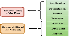
- The OSI model is divided into two layers: upper layers and lower layers.
- The upper layer of the OSI model mainly deals with the application related issues, and they are implemented only in the software. The application layer is closest to the end user. Both the end user and the application layer interact with the software applications. An upper layer refers to the layer just above another layer.
- The lower layer of the OSI model deals with the data transport issues. The data link layer and the physical layer are implemented in hardware and software. The physical layer is the lowest layer of the OSI model and is closest to the physical medium. The physical layer is mainly responsible for placing the information on the physical medium.
Functions of the OSI Layers
There are the seven OSI layers. Each layer has different functions. A list of seven layers are given below:
- Physical Layer
- Data-Link Layer
- Network Layer
- Transport Layer
- Session Layer
- Presentation Layer
- Application Layer
Physical layer
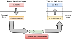
- The main functionality of the physical layer is to transmit the individual bits from one node to another node.
- It is the lowest layer of the OSI model.
- It establishes, maintains and deactivates the physical connection.
- It specifies the mechanical, electrical and procedural network interface specifications.
Functions of a Physical layer:
- Line Configuration: It defines the way how two or more devices can be connected physically.
- Data Transmission: It defines the transmission mode whether it is simplex, half-duplex or full-duplex mode between the two devices on the network.
- Topology: It defines the way how network devices are arranged.
- Signals: It determines the type of the signal used for transmitting the information.
Data-Link Layer
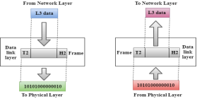
- This layer is responsible for the error-free transfer of data frames.
- It defines the format of the data on the network.
- It provides a reliable and efficient communication between two or more devices.
- It is mainly responsible for the unique identification of each device that resides on a local network.
- It contains two sub-layers:
- Logical Link Control Layer
- It is responsible for transferring the packets to the Network layer of the receiver that is receiving.
- It identifies the address of the network layer protocol from the header.
- It also provides flow control.
- Media Access Control Layer
- A Media access control layer is a link between the Logical Link Control layer and the network's physical layer.
- It is used for transferring the packets over the network.
- Logical Link Control Layer
Functions of the Data-link layer
- Framing: The data link layer translates the physical's raw bit stream into packets known as Frames. The Data link layer adds the header and trailer to the frame. The header which is added to the frame contains the hardware destination and source address.

- Physical Addressing: The Data link layer adds a header to the frame that contains a destination address. The frame is transmitted to the destination address mentioned in the header.
- Flow Control: Flow control is the main functionality of the Data-link layer. It is the technique through which the constant data rate is maintained on both the sides so that no data get corrupted. It ensures that the transmitting station such as a server with higher processing speed does not exceed the receiving station, with lower processing speed.
- Error Control: Error control is achieved by adding a calculated value CRC (Cyclic Redundancy Check) that is placed to the Data link layer's trailer which is added to the message frame before it is sent to the physical layer. If any error seems to occurr, then the receiver sends the acknowledgment for the retransmission of the corrupted frames.
- Access Control: When two or more devices are connected to the same communication channel, then the data link layer protocols are used to determine which device has control over the link at a given time.
Network Layer

- It is a layer 3 that manages device addressing, tracks the location of devices on the network.
- It determines the best path to move data from source to the destination based on the network conditions, the priority of service, and other factors.
- The Data link layer is responsible for routing and forwarding the packets.
- Routers are the layer 3 devices, they are specified in this layer and used to provide the routing services within an internetwork.
- The protocols used to route the network traffic are known as Network layer protocols. Examples of protocols are IP and Ipv6.
Functions of Network Layer:
- Internetworking: An internetworking is the main responsibility of the network layer. It provides a logical connection between different devices.
- Addressing: A Network layer adds the source and destination address to the header of the frame. Addressing is used to identify the device on the internet.
- Routing: Routing is the major component of the network layer, and it determines the best optimal path out of the multiple paths from source to the destination.
- Packetizing: A Network Layer receives the packets from the upper layer and converts them into packets. This process is known as Packetizing. It is achieved by internet protocol (IP).
Transport Layer
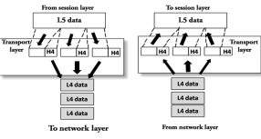
- The Transport layer is a Layer 4 ensures that messages are transmitted in the order in which they are sent and there is no duplication of data.
- The main responsibility of the transport layer is to transfer the data completely.
- It receives the data from the upper layer and converts them into smaller units known as segments.
- This layer can be termed as an end-to-end layer as it provides a point-to-point connection between source and destination to deliver the data reliably.
The two protocols used in this layer are:
- Transmission Control Protocol
- It is a standard protocol that allows the systems to communicate over the internet.
- It establishes and maintains a connection between hosts.
- When data is sent over the TCP connection, then the TCP protocol divides the data into smaller units known as segments. Each segment travels over the internet using multiple routes, and they arrive in different orders at the destination. The transmission control protocol reorders the packets in the correct order at the receiving end.
- User Datagram Protocol
- User Datagram Protocol is a transport layer protocol.
- It is an unreliable transport protocol as in this case receiver does not send any acknowledgment when the packet is received, the sender does not wait for any acknowledgment. Therefore, this makes a protocol unreliable.
Functions of Transport Layer:
- Service-point addressing: Computers run several programs simultaneously due to this reason, the transmission of data from source to the destination not only from one computer to another computer but also from one process to another process. The transport layer adds the header that contains the address known as a service-point address or port address. The responsibility of the network layer is to transmit the data from one computer to another computer and the responsibility of the transport layer is to transmit the message to the correct process.
- Segmentation and reassembly: When the transport layer receives the message from the upper layer, it divides the message into multiple segments, and each segment is assigned with a sequence number that uniquely identifies each segment. When the message has arrived at the destination, then the transport layer reassembles the message based on their sequence numbers.
- Connection control: Transport layer provides two services Connection-oriented service and connectionless service. A connectionless service treats each segment as an individual packet, and they all travel in different routes to reach the destination. A connection-oriented service makes a connection with the transport layer at the destination machine before delivering the packets. In connection-oriented service, all the packets travel in the single route.
- Flow control: The transport layer also responsible for flow control but it is performed end-to-end rather than across a single link.
- Error control: The transport layer is also responsible for Error control. Error control is performed end-to-end rather than across the single link. The sender transport layer ensures that message reach at the destination without any error.
Session Layer
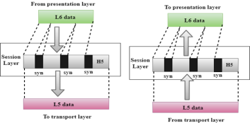
- It is a layer 3 in the OSI model.
- The Session layer is used to establish, maintain and synchronizes the interaction between communicating devices.
Functions of Session layer:
- Dialog control: Session layer acts as a dialog controller that creates a dialog between two processes or we can say that it allows the communication between two processes which can be either half-duplex or full-duplex.
- Synchronization: Session layer adds some checkpoints when transmitting the data in a sequence. If some error occurs in the middle of the transmission of data, then the transmission will take place again from the checkpoint. This process is known as Synchronization and recovery.
Presentation Layer
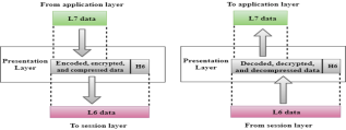
- A Presentation layer is mainly concerned with the syntax and semantics of the information exchanged between the two systems.
- It acts as a data translator for a network.
- This layer is a part of the operating system that converts the data from one presentation format to another format.
- The Presentation layer is also known as the syntax layer.
Functions of Presentation layer:
- Translation: The processes in two systems exchange the information in the form of character strings, numbers and so on. Different computers use different encoding methods, the presentation layer handles the interoperability between the different encoding methods. It converts the data from sender-dependent format into a common format and changes the common format into receiver-dependent format at the receiving end.
- Encryption: Encryption is needed to maintain privacy. Encryption is a process of converting the sender-transmitted information into another form and sends the resulting message over the network.
- Compression: Data compression is a process of compressing the data, i.e., it reduces the number of bits to be transmitted. Data compression is very important in multimedia such as text, audio, video.
Application Layer
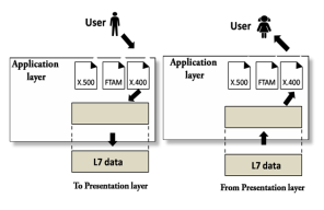
- An application layer serves as a window for users and application processes to access network service.
- It handles issues such as network transparency, resource allocation, etc.
- An application layer is not an application, but it performs the application layer functions.
- This layer provides the network services to the end-users.
Functions of Application layer:
- File transfer, access, and management (FTAM): An application layer allows a user to access the files in a remote computer, to retrieve the files from a computer and to manage the files in a remote computer.
- Mail services: An application layer provides the facility for email forwarding and storage.
- Directory services: An application provides the distributed database sources and is used to provide that global information about various objects.
TCP/IP model
- The TCP/IP model was developed prior to the OSI model.
- The TCP/IP model is not exactly similar to the OSI model.
- The TCP/IP model consists of five layers: the application layer, transport layer, network layer, data link layer and physical layer.
- The first four layers provide physical standards, network interface, internetworking, and transport functions that correspond to the first four layers of the OSI model and these four layers are represented in TCP/IP model by a single layer called the application layer.
- TCP/IP is a hierarchical protocol made up of interactive modules, and each of them provides specific functionality.
Here, hierarchical means that each upper-layer protocol is supported by two or more lower-level protocols.
Functions of TCP/IP layers:
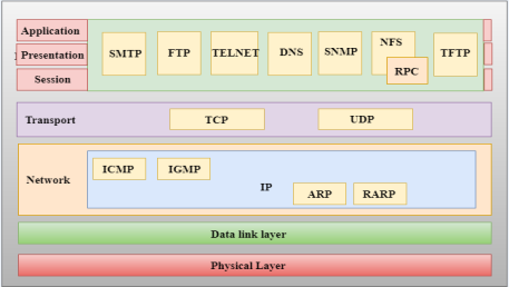
Network Access Layer
- A network layer is the lowest layer of the TCP/IP model.
- A network layer is the combination of the Physical layer and Data Link layer defined in the OSI reference model.
- It defines how the data should be sent physically through the network.
- This layer is mainly responsible for the transmission of the data between two devices on the same network.
- The functions carried out by this layer are encapsulating the IP datagram into frames transmitted by the network and mapping of IP addresses into physical addresses.
- The protocols used by this layer are ethernet, token ring, FDDI, X.25, frame relay.
Internet Layer
- An internet layer is the second layer of the TCP/IP model.
- An internet layer is also known as the network layer.
- The main responsibility of the internet layer is to send the packets from any network, and they arrive at the destination irrespective of the route they take.
Following are the protocols used in this layer are:
IP Protocol: IP protocol is used in this layer, and it is the most significant part of the entire TCP/IP suite.
Following are the responsibilities of this protocol:
- IP Addressing: This protocol implements logical host addresses known as IP addresses. The IP addresses are used by the internet and higher layers to identify the device and to provide internetwork routing.
- Host-to-host communication: It determines the path through which the data is to be transmitted.
- Data Encapsulation and Formatting: An IP protocol accepts the data from the transport layer protocol. An IP protocol ensures that the data is sent and received securely, it encapsulates the data into message known as IP datagram.
- Fragmentation and Reassembly: The limit imposed on the size of the IP datagram by data link layer protocol is known as Maximum Transmission unit (MTU). If the size of IP datagram is greater than the MTU unit, then the IP protocol splits the datagram into smaller units so that they can travel over the local network. Fragmentation can be done by the sender or intermediate router. At the receiver side, all the fragments are reassembled to form an original message.
- Routing: When IP datagram is sent over the same local network such as LAN, MAN, WAN, it is known as direct delivery. When source and destination are on the distant network, then the IP datagram is sent indirectly. This can be accomplished by routing the IP datagram through various devices such as routers.
ARP Protocol
- ARP stands for Address Resolution Protocol.
- ARP is a network layer protocol which is used to find the physical address from the IP address.
- The two terms are mainly associated with the ARP Protocol:
- ARP request: When a sender wants to know the physical address of the device, it broadcasts the ARP request to the network.
- ARP reply: Every device attached to the network will accept the ARP request and process the request, but only recipient recognize the IP address and sends back its physical address in the form of ARP reply. The recipient adds the physical address both to its cache memory and to the datagram header
ICMP Protocol
- ICMP stands for Internet Control Message Protocol.
- It is a mechanism used by the hosts or routers to send notifications regarding datagram problems back to the sender.
- A datagram travels from router-to-router until it reaches its destination. If a router is unable to route the data because of some unusual conditions such as disabled links, a device is on fire or network congestion, then the ICMP protocol is used to inform the sender that the datagram is undeliverable.
- An ICMP protocol mainly uses two terms:
- ICMP Test: ICMP Test is used to test whether the destination is reachable or not.
- ICMP Reply: ICMP Reply is used to check whether the destination device is responding or not.
- The core responsibility of the ICMP protocol is to report the problems, not correct them. The responsibility of the correction lies with the sender.
- ICMP can send the messages only to the source, but not to the intermediate routers because the IP datagram carries the addresses of the source and destination but not of the router that it is passed to.
Transport Layer
The transport layer is responsible for the reliability, flow control, and correction of data which is being sent over the network.
The two protocols used in the transport layer are User Datagram protocol and Transmission control protocol.
- User Datagram Protocol (UDP)
- It provides connectionless service and end-to-end delivery of transmission.
- It is an unreliable protocol as it discovers the errors but not specify the error.
- User Datagram Protocol discovers the error, and ICMP protocol reports the error to the sender that user datagram has been damaged.
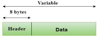
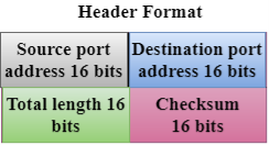
- UDP consists of the following fields:
Source port address: The source port address is the address of the application program that has created the message.
Destination port address: The destination port address is the address of the application program that receives the message.
Total length: It defines the total number of bytes of the user datagram in bytes.
Checksum: The checksum is a 16-bit field used in error detection. - UDP does not specify which packet is lost. UDP contains only checksum; it does not contain any ID of a data segment.
- Transmission Control Protocol (TCP)
- It provides a full transport layer services to applications.
- It creates a virtual circuit between the sender and receiver, and it is active for the duration of the transmission.
- TCP is a reliable protocol as it detects the error and retransmits the damaged frames. Therefore, it ensures all the segments must be received and acknowledged before the transmission is considered to be completed and a virtual circuit is discarded.
- At the sending end, TCP divides the whole message into smaller units known as segment, and each segment contains a sequence number which is required for reordering the frames to form an original message.
- At the receiving end, TCP collects all the segments and reorders them based on sequence numbers.
Application Layer
- An application layer is the topmost layer in the TCP/IP model.
- It is responsible for handling high-level protocols, issues of representation.
- This layer allows the user to interact with the application.
- When one application layer protocol wants to communicate with another application layer, it forwards its data to the transport layer.
- There is an ambiguity occurs in the application layer. Every application cannot be placed inside the application layer except those who interact with the communication system. For example: text editor cannot be considered in application layer while web browser using HTTP protocol to interact with the network where HTTP protocol is an application layer protocol.
Following are the main protocols used in the application layer:
- HTTP: HTTP stands for Hypertext transfer protocol. This protocol allows us to access the data over the world wide web. It transfers the data in the form of plain text, audio, video. It is known as a Hypertext transfer protocol as it has the efficiency to use in a hypertext environment where there are rapid jumps from one document to another.
- SNMP: SNMP stands for Simple Network Management Protocol. It is a framework used for managing the devices on the internet by using the TCP/IP protocol suite.
- SMTP: SMTP stands for Simple mail transfer protocol. The TCP/IP protocol that supports the e-mail is known as a Simple mail transfer protocol. This protocol is used to send the data to another e-mail address.
- DNS: DNS stands for Domain Name System. An IP address is used to identify the connection of a host to the internet uniquely. But, people prefer to use the names instead of addresses. Therefore, the system that maps the name to the address is known as Domain Name System.
- TELNET: It is an abbreviation for Terminal Network. It establishes the connection between the local computer and remote computer in such a way that the local terminal appears to be a terminal at the remote system.
- FTP: FTP stands for File Transfer Protocol. FTP is a standard internet protocol used for transmitting the files from one computer to another computer.
Computer Network Types
A computer network is a group of computers linked to each other that enables the computer to communicate with another computer and share their resources, data, and applications.
A computer network can be categorized by their size. A computer network is mainly of four types:
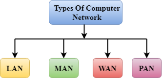
- LAN(Local Area Network)
- PAN(Personal Area Network)
- MAN(Metropolitan Area Network)
- WAN(Wide Area Network)
LAN(Local Area Network)
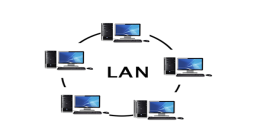
- Local Area Network is a group of computers connected to each other in a small area such as building, office.
- LAN is used for connecting two or more personal computers through a communication medium such as twisted pair, coaxial cable, etc.
- It is less costly as it is built with inexpensive hardware such as hubs, network adapters, and ethernet cables.
- The data is transferred at an extremely faster rate in Local Area Network.
- Local Area Network provides higher security.
PAN(Personal Area Network)
- Personal Area Network is a network arranged within an individual person, typically within a range of 10 meters.
- Personal Area Network is used for connecting the computer devices of personal use is known as Personal Area Network.
- Thomas Zimmerman was the first research scientist to bring the idea of the Personal Area Network.
- Personal Area Network covers an area of 30 feet.
- Personal computer devices that are used to develop the personal area network are the laptop, mobile phones, media player and play stations.
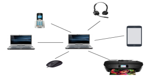
There are two types of Personal Area Network:
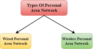
- Wired Personal Area Network
- Wireless Personal Area Network
Wireless Personal Area Network: Wireless Personal Area Network is developed by simply using wireless technologies such as WiFi, Bluetooth. It is a low range network.
Wired Personal Area Network: Wired Personal Area Network is created by using the USB.
Examples Of Personal Area Network:
- Body Area Network: Body Area Network is a network that moves with a person. For example, a mobile network moves with a person. Suppose a person establishes a network connection and then creates a connection with another device to share the information.
- Offline Network: An offline network can be created inside the home, so it is also known as a home network. A home network is designed to integrate the devices such as printers, computer, television but they are not connected to the internet.
- Small Home Office: It is used to connect a variety of devices to the internet and to a corporate network using a VPN
MAN(Metropolitan Area Network)
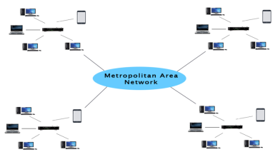
- A metropolitan area network is a network that covers a larger geographic area by interconnecting a different LAN to form a larger network.
- Government agencies use MAN to connect to the citizens and private industries.
- In MAN, various LANs are connected to each other through a telephone exchange line.
- The most widely used protocols in MAN are RS-232, Frame Relay, ATM, ISDN, OC-3, ADSL, etc.
- It has a higher range than Local Area Network(LAN).
Uses Of Metropolitan Area Network:
- MAN is used in communication between the banks in a city.
- It can be used in an Airline Reservation.
- It can be used in a college within a city.
- It can also be used for communication in the military.
WAN(Wide Area Network)
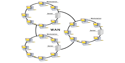
- A Wide Area Network is a network that extends over a large geographical area such as states or countries.
- A Wide Area Network is quite bigger network than the LAN.
- A Wide Area Network is not limited to a single location, but it spans over a large geographical area through a telephone line, fibre optic cable or satellite links.
- The internet is one of the biggest WAN in the world.
- A Wide Area Network is widely used in the field of Business, government, and education.
Examples Of Wide Area Network:
- Mobile Broadband: A 4G network is widely used across a region or country.
- Last mile: A telecom company is used to provide the internet services to the customers in hundreds of cities by connecting their home with fiber.
- Private network: A bank provides a private network that connects the 44 offices. This network is made by using the telephone leased line provided by the telecom company.
Advantages Of Wide Area Network:
Following are the advantages of the Wide Area Network:
- Geographical area: A Wide Area Network provides a large geographical area. Suppose if the branch of our office is in a different city then we can connect with them through WAN. The internet provides a leased line through which we can connect with another branch.
- Centralized data: In case of WAN network, data is centralized. Therefore, we do not need to buy the emails, files or back up servers.
- Get updated files: Software companies work on the live server. Therefore, the programmers get the updated files within seconds.
- Exchange messages: In a WAN network, messages are transmitted fast. The web application like Facebook, Whatsapp, Skype allows you to communicate with friends.
- Sharing of software and resources: In WAN network, we can share the software and other resources like a hard drive, RAM.
- Global business: We can do the business over the internet globally.
- High bandwidth: If we use the leased lines for our company then this gives the high bandwidth. The high bandwidth increases the data transfer rate which in turn increases the productivity of our company.
Disadvantages of Wide Area Network:
The following are the disadvantages of the Wide Area Network:
- Security issue: A WAN network has more security issues as compared to LAN and MAN network as all the technologies are combined together that creates the security problem.
- Needs Firewall & antivirus software: The data is transferred on the internet which can be changed or hacked by the hackers, so the firewall needs to be used. Some people can inject the virus in our system so antivirus is needed to protect from such a virus.
- High Setup cost: An installation cost of the WAN network is high as it involves the purchasing of routers, switches.
- Troubleshooting problems: It covers a large area so fixing the problem is difficult.
Internetwork
- An internetwork is defined as two or more computer network LANs or WAN or computer network segments are connected using devices, and they are configured by a local addressing scheme. This process is known as internetworking.
- An interconnection between public, private, commercial, industrial, or government computer networks can also be defined as internetworking.
- An internetworking uses the internet protocol.
- The reference model used for internetworking is Open System Interconnection(OSI).
Types Of Internetwork:
1. Extranet: An extranet is a communication network based on the internet protocol such as Transmission Control protocol and internet protocol. It is used for information sharing. The access to the extranet is restricted to only those users who have login credentials. An extranet is the lowest level of internetworking. It can be categorized as MAN, WAN or other computer networks. An extranet cannot have a single LAN, atleast it must have one connection to the external network.
2. Intranet: An intranet is a private network based on the internet protocol such as Transmission Control protocol and internet protocol. An intranet belongs to an organization which is only accessible by the organization's employee or members. The main aim of the intranet is to share the information and resources among the organization employees. An intranet provides the facility to work in groups and for teleconferences.
Intranet advantages:
- Communication: It provides a cheap and easy communication. An employee of the organization can communicate with another employee through email, chat.
- Time-saving: Information on the intranet is shared in real time, so it is time-saving.
- Collaboration: Collaboration is one of the most important advantage of the intranet. The information is distributed among the employees of the organization and can only be accessed by the authorized user.
- Platform independency: It is a neutral architecture as the computer can be connected to another device with different architecture.
- Cost effective: People can see the data and documents by using the browser and distributes the duplicate copies over the intranet. This leads to a reduction in the cost.
What is Topology?
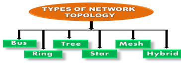
Topology defines the structure of the network of how all the components are interconnected to each other. There are two types of topology: physical and logical topology.
Physical topology is the geometric representation of all the nodes in a network.
Bus Topology
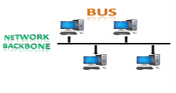
- The bus topology is designed in such a way that all the stations are connected through a single cable known as a backbone cable.
- Each node is either connected to the backbone cable by drop cable or directly connected to the backbone cable.
- When a node wants to send a message over the network, it puts a message over the network. All the stations available in the network will receive the message whether it has been addressed or not.
- The bus topology is mainly used in 802.3 (ethernet) and 802.4 standard networks.
- The configuration of a bus topology is quite simpler as compared to other topologies.
- The backbone cable is considered as a "single lane" through which the message is broadcast to all the stations.
- The most common access method of the bus topologies is CSMA (Carrier Sense Multiple Access).
CSMA: It is a media access control used to control the data flow so that data integrity is maintained, i.e., the packets do not get lost. There are two alternative ways of handling the problems that occur when two nodes send the messages simultaneously.
- CSMA CD: CSMA CD (Collision detection) is an access method used to detect the collision. Once the collision is detected, the sender will stop transmitting the data. Therefore, it works on "recovery after the collision".
- CSMA CA: CSMA CA (Collision Avoidance) is an access method used to avoid the collision by checking whether the transmission media is busy or not. If busy, then the sender waits until the media becomes idle. This technique effectively reduces the possibility of the collision. It does not work on "recovery after the collision".
Advantages of Bus topology:
- Low-cost cable: In bus topology, nodes are directly connected to the cable without passing through a hub. Therefore, the initial cost of installation is low.
- Moderate data speeds: Coaxial or twisted pair cables are mainly used in bus-based networks that support upto 10 Mbps.
- Familiar technology: Bus topology is a familiar technology as the installation and troubleshooting techniques are well known, and hardware components are easily available.
- Limited failure: A failure in one node will not have any effect on other nodes.
Disadvantages of Bus topology:
- Extensive cabling: A bus topology is quite simpler, but still it requires a lot of cabling.
- Difficult troubleshooting: It requires specialized test equipment to determine the cable faults. If any fault occurs in the cable, then it would disrupt the communication for all the nodes.
- Signal interference: If two nodes send the messages simultaneously, then the signals of both the nodes collide with each other.
- Reconfiguration difficult: Adding new devices to the network would slow down the network.
- Attenuation: Attenuation is a loss of signal leads to communication issues. Repeaters are used to regenerate the signal.
Ring Topology

- Ring topology is like a bus topology, but with connected ends.
- The node that receives the message from the previous computer will retransmit to the next node.
- The data flows in one direction, i.e., it is unidirectional.
- The data flows in a single loop continuously known as an endless loop.
- It has no terminated ends, i.e., each node is connected to other node and having no termination point.
- The data in a ring topology flow in a clockwise direction.
- The most common access method of the ring topology is token passing.
- Token passing: It is a network access method in which token is passed from one node to another node.
- Token: It is a frame that circulates around the network.
Working of Token passing
- A token moves around the network, and it is passed from computer to computer until it reaches the destination.
- The sender modifies the token by putting the address along with the data.
- The data is passed from one device to another device until the destination address matches. Once the token received by the destination device, then it sends the acknowledgment to the sender.
- In a ring topology, a token is used as a carrier.
Advantages of Ring topology:
- Network Management: Faulty devices can be removed from the network without bringing the network down.
- Product availability: Many hardware and software tools for network operation and monitoring are available.
- Cost: Twisted pair cabling is inexpensive and easily available. Therefore, the installation cost is very low.
- Reliable: It is a more reliable network because the communication system is not dependent on the single host computer.
Disadvantages of Ring topology:
- Difficult troubleshooting: It requires specialized test equipment to determine the cable faults. If any fault occurs in the cable, then it would disrupt the communication for all the nodes.
- Failure: The breakdown in one station leads to the failure of the overall network.
- Reconfiguration difficult: Adding new devices to the network would slow down the network.
- Delay: Communication delay is directly proportional to the number of nodes. Adding new devices increases the communication delay.
Star Topology
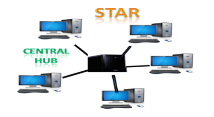
- Star topology is an arrangement of the network in which every node is connected to the central hub, switch or a central computer.
- The central computer is known as a server, and the peripheral devices attached to the server are known as clients.
- Coaxial cable or RJ-45 cables are used to connect the computers.
- Hubs or Switches are mainly used as connection devices in a physical star topology.
- Star topology is the most popular topology in network implementation.
Advantages of Star topology
- Efficient troubleshooting: Troubleshooting is quite efficient in a star topology as compared to bus topology. In a bus topology, the manager has to inspect the kilometers of cable. In a star topology, all the stations are connected to the centralized network. Therefore, the network administrator has to go to the single station to troubleshoot the problem.
- Network control: Complex network control features can be easily implemented in the star topology. Any changes made in the star topology are automatically accommodated.
- Limited failure: As each station is connected to the central hub with its own cable, therefore failure in one cable will not affect the entire network.
- Familiar technology: Star topology is a familiar technology as its tools are cost-effective.
- Easily expandable: It is easily expandable as new stations can be added to the open ports on the hub.
- Cost effective: Star topology networks are cost-effective as it uses inexpensive coaxial cable.
- High data speeds: It supports a bandwidth of approx 100Mbps. Ethernet 100BaseT is one of the most popular Star topology networks.
Disadvantages of Star topology
- A Central point of failure: If the central hub or switch goes down, then all the connected nodes will not be able to communicate with each other.
- Cable: Sometimes cable routing becomes difficult when a significant amount of routing is required.
Tree topology
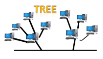
- Tree topology combines the characteristics of bus topology and star topology.
- A tree topology is a type of structure in which all the computers are connected with each other in hierarchical fashion.
- The top-most node in tree topology is known as a root node, and all other nodes are the descendants of the root node.
- There is only one path exists between two nodes for the data transmission. Thus, it forms a parent-child hierarchy.
Advantages of Tree topology
- Support for broadband transmission: Tree topology is mainly used to provide broadband transmission, i.e., signals are sent over long distances without being attenuated.
- Easily expandable: We can add the new device to the existing network. Therefore, we can say that tree topology is easily expandable.
- Easily manageable: In tree topology, the whole network is divided into segments known as star networks which can be easily managed and maintained.
- Error detection: Error detection and error correction are very easy in a tree topology.
- Limited failure: The breakdown in one station does not affect the entire network.
- Point-to-point wiring: It has point-to-point wiring for individual segments.
Disadvantages of Tree topology
- Difficult troubleshooting: If any fault occurs in the node, then it becomes difficult to troubleshoot the problem.
- High cost: Devices required for broadband transmission are very costly.
- Failure: A tree topology mainly relies on main bus cable and failure in main bus cable will damage the overall network.
- Reconfiguration difficult: If new devices are added, then it becomes difficult to reconfigure.
Mesh topology
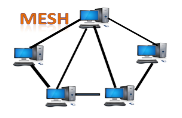
- Mesh technology is an arrangement of the network in which computers are interconnected with each other through various redundant connections.
- There are multiple paths from one computer to another computer.
- It does not contain the switch, hub or any central computer which acts as a central point of communication.
- The Internet is an example of the mesh topology.
- Mesh topology is mainly used for WAN implementations where communication failures are a critical concern.
- Mesh topology is mainly used for wireless networks.
- Mesh topology can be formed by using the formula:
Number of cables = (n*(n-1))/2;
Where n is the number of nodes that represents the network.
Mesh topology is divided into two categories:
- Fully connected mesh topology
- Partially connected mesh topology

- Full Mesh Topology: In a full mesh topology, each computer is connected to all the computers available in the network.
- Partial Mesh Topology: In a partial mesh topology, not all but certain computers are connected to those computers with which they communicate frequently.
Advantages of Mesh topology:
Reliable: The mesh topology networks are very reliable as if any link breakdown will not affect the communication between connected computers.
Fast Communication: Communication is very fast between the nodes.
Easier Reconfiguration: Adding new devices would not disrupt the communication between other devices.
Disadvantages of Mesh topology
- Cost: A mesh topology contains a large number of connected devices such as a router and more transmission media than other topologies.
- Management: Mesh topology networks are very large and very difficult to maintain and manage. If the network is not monitored carefully, then the communication link failure goes undetected.
- Efficiency: In this topology, redundant connections are high that reduces the efficiency of the network.
Hybrid Topology
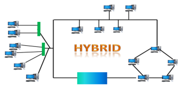
- The combination of various different topologies is known as Hybrid topology.
- A Hybrid topology is a connection between different links and nodes to transfer the data.
- When two or more different topologies are combined together is termed as Hybrid topology and if similar topologies are connected with each other will not result in Hybrid topology. For example, if there exist a ring topology in one branch of ICICI bank and bus topology in another branch of ICICI bank, connecting these two topologies will result in Hybrid topology.
Advantages of Hybrid Topology
- Reliable: If a fault occurs in any part of the network will not affect the functioning of the rest of the network.
- Scalable: Size of the network can be easily expanded by adding new devices without affecting the functionality of the existing network.
- Flexible: This topology is very flexible as it can be designed according to the requirements of the organization.
- Effective: Hybrid topology is very effective as it can be designed in such a way that the strength of the network is maximized and weakness of the network is minimized.
Disadvantages of Hybrid topology
- Complex design: The major drawback of the Hybrid topology is the design of the Hybrid network. It is very difficult to design the architecture of the Hybrid network.
- Costly Hub: The Hubs used in the Hybrid topology are very expensive as these hubs are different from usual Hubs used in other topologies.
- Costly infrastructure: The infrastructure cost is very high as a hybrid network requires a lot of cabling, network devices, etc.