Unit -1
Fundamental of statistics
- Introduction
Engineering machines is that branch of science which deals with behavior of a body when body is at rest or in motion knowledge of engineering machines is very essential for engineer in planning designing and construction of various structure and machines.
Engineering machines is divided into two parts
- Static
- Dynamic
- Static:-it is a branch of engineering machines which deals with body when body is at rest.
- Dynamics:-it is branch of engineering machines which deals with body when body is in motion.
Dynamic is further divided into two parts.
- Kinematics
- Kinetics
- Kinematics:-it is branch of dynamics which deals with motion of body only the forces which cause motion is not considered.
- Kinetics:-it is branch of dynamics which deals with bodies in motion due to application of forces.
Note:-
1. Static deals with equilibrium of bodies at rest.
2. Dynamic deals with motion of bodies and forces that cause them.
Fundamental units:-
Measurement of physical qualities is one of the most important operation in engineering quantity is measured in terms of some arbitrary but internationally accepted units called fundamental units.
There are three fundamental qualities which met with in engineering machine
- Length
- Mass
- Time
- Derived units:-units which are derived from fundamental units are known as derived unit
Example:-unit of area ,velocity, acceleration etc.
- System of units:-the following system of units are mostly used
- C.G.S units
- M.K.S units
- S.I units
C.G.S units (i.e Centimetres- gram- second):-in this system length be expressed as centimetres mass in gram and time in seconds.
M.K.S unit (i.e metre -kilogram-second):-in this system length be expressed in metre mass in kilogram and time in seconds.
S.I unit (international system of units):-in this system fundamental units length is expressed in metre mass in kilogram and time in seconds
- Metres:-international meta is may be defined as the shortest distance ,0c between two parallel lines engrained upon polished surface of platinum iridium by kept at international burean of weights and measures at service near Paris.
- Kilogram:-international kilogram may be defined as the mass of platinum iridium cylinder which is also kept at international bureau of weights and measures at severes near Paris.
- Second:-fundamental unit for all three system is second which is
 of mean solar day .A solar may be defined as internal of time between the instants at which the sun crosses the meridian on two consecutive days the average of all solar days of 1 year is called means solar days.
 - Presentation of units and their values:-we already discussed in previous article units of length mass and time are metre , kilogram and second (according to S.I system of unit) respectively .According to convenience we also use larger multiples of smaller fractions of these units as a typical example metre is unit of length yet smaller length equal to 1000 of metre proves to be more convenient unit especially in the dimensioning drawings such convenient units are formed by using profit in front of basic unit to indicate the multiplier.
Table:S1 Prefixes
Multiplication factor | Prefix | Symbol |
1000000000000=  | Tera | T |
1000000000=  | Giga | G |
1000000=  | Mega | M |
1000=  | Kilo | K |
100=  | Hecta | H |
10=  | Deca | Da |
0.1=  | Deci | d |
0.01=  | Centi | c |
0.001=  | Milli | m |
0.0000001=  | Micro |  |
0.0000000001=  | Nano | n |
0.0000000000001=  | Pico | p |
- Scalar quantities:-scalar quantities are those quantities which can completely specified by magnitude only such as mass time distance volume etc.
- Vector quantities:-quantities are those quantities which incompletely specified by magnitude as well as its direction.
Such as force,displacement ,velocity ,acceleration momentum etc.
Vector is represented by a directed line are shown in figure 1.

Length OA represent magnitude of vector  . Direction of vector
  Is from o to A. It B also known as vector p.
- Unit vector:-a vector whose magnitude is unity is known as unit vector.
- Equal vectors:-The vectors which are parallel to each other and have some direction that is some sense and equal magnitude are known as equal vectors.
- Like vector:-the factor which are parallel to each other and have same direction but an equal magnitude are known as like vectors.
- Addition of vectors:-consider two vector PQ and RS which are required to be added as shown in figure 2 (a) .
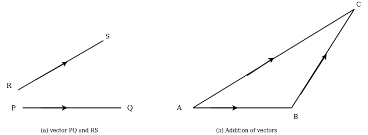
Take point A draw a line AB parallel to PQ and equal in magnitude to vector PQ to some convenient scale. Through point B through line BC parallel to vector RS to some scale. Join AC which will give addition to vector  as shown in fig 2(b)
This method of adding two vector is called triangle law of addition of vectors.
If more than two vectors to be added the same may be done by first adding two vectors and then resultant of these vector is added to third vector and so on this method of adding more than two vectors is called polygon law of addition of vectors.
- Subtraction of vectors:-consider two vector PQ and RS in which RS B required to be subtracted as shown in figure 3
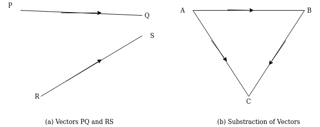
Take point A draw line AB parallel and equal a magnitude to vector PQ to some convenient scale through B draw line BC parallel to the other RS but in opposite direction to vector RS to some scale. join AC which will give resultant when vector PQ and RS are subtracted as shown in figure 3b
Force is an important factor in field of mechanic which may be broadly defined as an agent which produce or tends to produce destroy or tends to destroy motion e.g a horse applies force to pull on cart and set in motion.
A force can be exerted by actual content like push or pull or at distance as in case of gravitational or magnetic forces a force in characterized by its point of application its magnitude and its direction a force is represented by vector
- Principle of physical independence of forces:-it States,” if a number of forces are simultaneous Lee acting on a body then resultant of these forces will have some effects as produced by all forces”.
- Principle of transmissibility of forces:-
Its States ,”if a force at any point but rigid body it may also be considered to act at any other point on it’s time of action provided this point is rigidly connected with the body”.
Note:-Richard body may be defined as a body which can retain its shape and size even if subjected to some external forces an actual practice no body is perfectly rigid but for sake of simplicity we take all bodies as rigid body.
- System of forces:-when two or more forces act on a system or a body simultaneous Lee it is known as a force system or system of force.
- Classification of force system
1) Coplanar
2) Non coplanar
Coplanar:-
1) Collinear
2) Concurrent
3) Parallel
4) Non concurrent non parallel
Non coplanar:-
1) Concurrent
2) Parallel
3) Non concurrent non parallel
Coplanar force system:-
If all forces acting on a body are in same plane then force system is known as coplanar force system.
1) Coplanar collinear
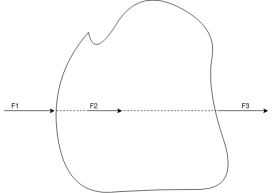
When all forces acts on body are in same plane and line of action of all forces acts along same line then system is known as coplanar collinear force system.
Example:-
Forces on rope in tug of war
2) Coplanar concurrent
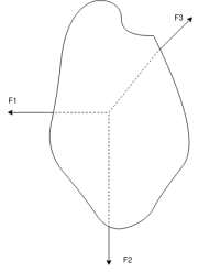
When all forces acting on body are in same plane and line of action of forces passes through single force then the system is known as coplanar concurrent force system.
Example:- Gusset plate of electric tower
3) Coplanar parallel
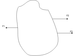
When all forces acting on a body are in same plane at their line of action of forces are parallel to each other then system is known as coplanar parallel force system.
Example:- beam subjected to vertical loading
4) Coplanar non concurrent non parallel
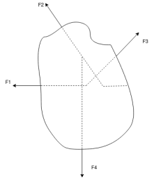
When all forces acting on a body are in same plane but they are neither parallel known concurrent then system is known as coplanar non concurrent non parallel force system.
Example:- forces on ladder resting against wall when person stands on rung which is not at its centre of gravity.
This force system is also known as general system of forces.
Non coplanar force system:-
If forces acting on a body are in different plane then force system is known as non coplanar force system.
1) Non coplanar concurrent
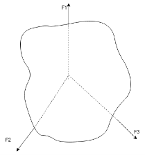
When all forces acting on a body do not lie in same plane but their line of action pass through a single point then force system is known as non coplanar concurrent force system.
Example:- electric pole supported by guy wire
2) Non coplanar parallel
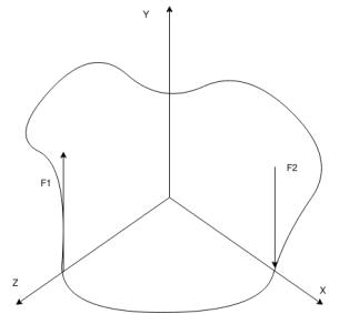
When all forces acting on a body are parallel to each other but do not lie in same plane then the force system is known as non coplanar parallel force system.
Example:- Weight of benches in classroom.
3) Non coplanar non concurrent non parallel
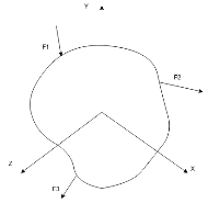
When all forces acting on a body do not lie in same plane and neither they are parallel or concurrent then force system is known as known coplanar non concurrent non parallel force system.
Example:- forces acting on moving bus.
Resultant of forces:-
If number of forces  etc acting simultaneously on a rigid body then it is possible to find out a single force which would replace them i.e. which would produce the same effect as produced by all given forces. This single force is called resultant force.
- Composition of force:-the process of finding out the resultant force of number of given force is called composition of forces or compounding of forces.
- Methods of resultant force
- Analytical method
- Graphical method
- Analytical method
- Parallelogram law of forces
- Method of resolution
Parallelogram law of forces:-It states” if two forces acting simultaneously on a body be represented in magnitude and direction by two adjacent sides of parallelogram their resultant may be represented in magnitude and direction by diagonal of the parallelogram which passes through their point of intersection.”
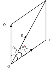
Let two forces P and Q at act as point O as shown in figure.11(a). The force P is represented in magnitude and direction by OA when force is represented in magnitude and direction by OB.

Let angle between two forces be x. The resultant of the forces will be obtained in magnitude and direction by diagonal (passing through O) of parallelogram of which OA and OB are two adjacent sides .Hence draw parallelogram with a and OA and OB as adjacent sides as shown in figure11(b) the resultant RB represented by OC in magnitude and direction.
Magnitude of resultant (R)
From C draw CD perpendicular to a produced
Let  =angle between two forces p and Q=
Now,

In parallelogram OACB. AC is parallel and equal to OB
AC=Q
In triangle ACD,
AD=AC Cos =QCos
=QCos
CD=AC Sin =Q Sin
In triangle OCD

OC=R
OD=OA+AD
=P + Q Cos
DC=Q Sin


Magnitude of resultant=
Direction of resultant
Let  =angle made by resultant R with OA.
Then from 


Direction of resultant=
Note:-
If 
Then 


If P=Q and acting at an angle between then=
Then


3. It is not necessary that one of two forces should be along x axis. The forces P and Q may be any direction as shown in figure 12
Example 01:-two forces of 100N and 150N are acting simultaneously at a point what is the resultant of these two forces if angle between then there is 45°
Solution:-Given
P=100N
Q=150N
 =45°
=45°


R=231.76N
Example 02:- find magnitude of two forces such that if they are at right angle their resultant is  N. But if they act at 60° resultant is
Solution:-
Let  are two forces.

For 

Squaring on both sides

Also for 

Squaring on both sides


We know


Similarly


Solving equation 1 and 2


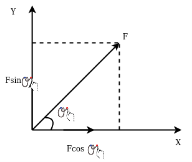 Resolution of a force:-the process of splitting up given force into a number of components without changing its effect on body is called as resolution of force. Generally of force is resolved along two mutually perpendicular directions as shown in figure 13
Light figure 13 force which makes an angle of Q with x axis
Component of f along x axis=
Component of f along y axis=
- Principle of resolution:-it states”
The algebraic sum of resolved parts of a number of force in a given direction is equal to the re solve part of their resultant in same direction”
Example 03:-A machine component 1.5 metre long and weight 1,000 N is supported by to ab and CD as shown in figure 14.

Solution:-Given
Weight=1000N
Tension  can be resolved in two component

Similarly tension  can be resolved in two component

As shown in Fig.15
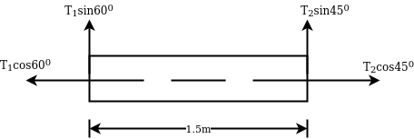
From Fig 15
We can say


Also


Method of resolution for resultant force
- Resolve all forces horizontally and find algebraic sum of all horizontal component i.e.

- Resolve all forces vertically and fine eligible sum of all vertical component i.e.

- The resultant R of given forces will be given by equation.

- The resultant force will be inclined at an angle
 with horizontal such that

Example 04:-a triangle ABC has its side ab = 240 mm along positive x axis and side BC=30 mm along positive y axis. Three forces QON, 50N and 30N act along the AB,BC and CA respectively determine magnitude of resultant of a system of force
Solution:- Given


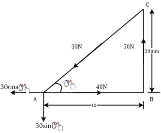

Now,
Resolving all forces horizontally


Resolving all forces vertically


Magnitude of resultant force=R=


Example 05:-A system of forces are acting at corners of rectangular block as shown in figure 17 determine magnitude and direction of resultant force.
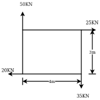 Solution:- Resolving all forces horizontally

=5KN
Resolving all forces vertically


Magnitude of resultant R=


Direction of resultant
Let  =angle which resultant force makes with horizontal


=-17

Since  is positive and
  is negative resultant lies in between 270° and 360°
Actual angle of resultant force


Note:- the value of  will vary depending upon the values of
  and
and  as discussed below.
1) When  is a positive resultant makes an angle between 0° and 180° but when
  is negative resultant makes an angle between 180° and 360°
2) When  is positive resultant makes an angle between 0° to 90°or 270° to 360° but when
  is negative resultant makes an angle between 90° to 270°.
Example 06:- The following forces acting at a point
- 20N inclined at 30° towards north of East.
- 25N towards north.
- 30N towards north west.
- 35N inclined at 40° towards south of west.
Find magnitude and direction of resultant force
Solution:- The system of forces from given
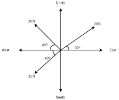
Magnitude of resultant force.
Resolving all forces horizontally


Resolving all forces vertically

=93.71N
Magnitude of resultant force


Direction of resultant force


Since  is negative and
  is positive resultant has between
  thus actual angle of resultant =

- Triangle law of forces
- Polygon law of forces
Triangle law of forces:-it States ,”if two forces acting simultaneously on particle be represented in magnitude and direction by two sides triangle taken in order then their resultant may be represented in magnitude and direction by third side of triangle taken in opposite order.”
Polygon law of forces:-it is an extension of triangle law of forces for more than two forces it States ,”if a number of forces acting simultaneously on a particle be represented in magnitude and direction by the side of polygon taken in order then the resultant of these forces may be represented in magnitude and direction by closing side of polygon taken in opposite direction.”
Graphical method:-it is another name for finding magnitude and direction of resultant force by polygon law of forces procedure for graphical method is discussed below
Construction of space diagram:-construct a diagram showing various forces along with their magnitude and life of action
- Use of Bows motions:-All forces in space diagram and names by using Bowe motion every force is named by to capital letters placed on either side in space diagram.
- Construction of vector diagram (force diagram):-it means construction of diagram starting from convenient point then go on adding all forces with your really one by one keeping in view the directions of forces to some suitable scale.
Now closing side of polygon taken in opposite direction will give magnitude and direction of resultant
Example 07:-the following forces act at a point
2 20N incline that 30° towards north of East.
3 25N towards north.
4 30N towards north west
5 35N in client at 40° towards south of West.
Find resultant magnitude and direction using graphical method
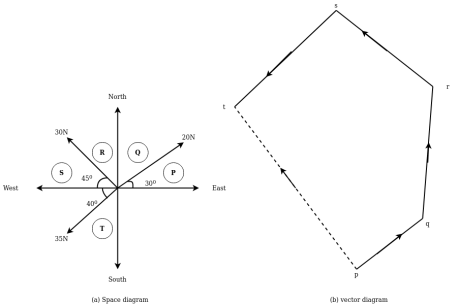
Resultant R=8.8cm
=8.8cm*5
=44N
Direction of resultant =
- Movement of a force:-it is turning effect produced by a force on the body the movement of is equal to the product of force and perpendicular distance of point about which the movement is required and line of action force.
Mathematically:- moment (m) =p×l
Where, p=force acting on body
l =perpendicular distance between the point about which movement is required and line of action of the force
Unit of moment:-if force is in Newton and distance is in metre then unit of moment is Newton metre (Mm)
Types of moment:-
- Clockwise moment
- Anticlockwise moment
- Clockwise moment:-it is the moment of force whose effect is to turn on rotate the body about a point in the same direction in which hand of clock moves as
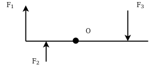 shown in figure 20
2. Anticlockwise moment:-it is the movement of food who is affected to turn on rotate the body about the point in the opposite direction in which hands of clock moves as shown in figure 21.
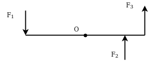
Note:-in general convention is to take clockwise movement on positive and anticlockwise movement as negative
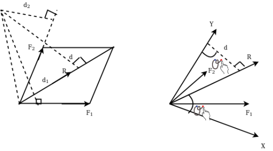
- Varignon's principle of moments a law of moments:- It states,” the algebraic sum of moments of a system of coplanar forces about a moment centre in the plane is equal to moment of their resultant force about same movement centre.”
Proof:- let R be the resultant of forces  and B the moment centre. Let d,
 be the moment and arm ( perpendicular distance of point from the line of action of force) of forces. Respectively from movement centre (point about which movement is considered) B then in this case we have to prove that

Join AB and considered it as y axis and draw exercise at right angle to it at a as shown in figure 22( b).
Denoting by Q the angle that R makes with x axis and noting that the same angle is formed by perpendicular to R at B with  we can write


Where
 component of R in x-direction
Similarly, if  are component of
  in x-direction then,


Add equations 2 and 3
 )
)

From equation 1

Note:- a system of forces consists of more than two forces then

Example 08:- Find moment of 100 N force acting at be about point as shown in figure 2b.
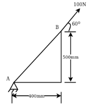
Solution:-100N force can be resolved into its horizontal component  and its vertical component
  from varignon’s theorem, moment of 100N force about point a is equal to algebraic sum of moments of its component about point A.
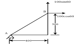


 anticlockwise
Note:-To decide direction of movement put your one finger on moment centre and other one at arrowhead of force and try to rotate your finger which is on arrowhead observe is it rotating clockwise or anticlockwise.
 Example 09:- What will be y-intercept of 5000N force if its movement about AB 8000 N.m in figure24
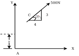
Solution:-5000N forces can be shifted to point B along its line of action low of transmissibility and its be resolved into its X and y components shown in figure 25


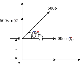
Now


According to Varignon’s theorem


Example 10:- Four forces equal to p, 2p,3p and 4p are respectively along four sides of a square ABCD taken in order find magnitude and direction and position of resultant force
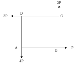 Solution:-
Let sides of square is u unit.
Magnitude of resultant force R
Resolving forces horizontally


Resolving forces vertically


Resultant force (R)=


Direction of resultant


Position of resultant
Let x= perpendicular distance between A and line of action of resultant force.
Now taking moments about point A
According to varignon’s theorem


-ve sign indicate anticlockwise moment

Note:- force p and 3p passing through point a therefore the moment about point a is zero.
Example 11:-four parallel forces of magnitude 100N ,150N ,25N and 200 N as shown in figure 25 determine magnitude of resultant and also distance of resultant from point A.
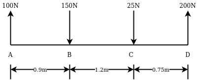
Solution:-All forces are vertical
Resultant ® = 100-150-25+ 200
= 125N
The sign indicate that resultant is upward
Let x= distance between resultant and point A
Applying varignon’s theorem
R × x= 150×0.9+25×2.1-200×2.85
125 ×x= -382.5 N.m
Negative sign indicates that anticlockwise direction of resultant
X=3.06 m
Couple:-two parallel forces equal in magnitude and opposite in direction and separated by a definite distance are set to form a couple (refer fig26) the sum of forces forming couple is zero since they are equal and opposite which means translate your faith of couple is zero but it produces a motion of rotation body on which it act.
Arm of couple:-The perpendicular distance(a) between line of action of two equal and opposite forces is known as arm of couple as shown in figure 26
Movement of a couple:-The moment of a couple is product of force and arm of couple.
 Mathematically, moment of couple=p×a
Where, p= magnitude of force
a= arm of couple
Classification of couples
- Clockwise couple
- Anticlockwise couple
- Clockwise couple:-A couple whose tendency is to rotate the body on which it act in clockwise direction is known as clockwise couple as shown in figure 27( a).
- Anticlockwise couple:-A couple whose tendency is to rotate the body on which it act in anticlockwise direction is known as anti clockwise couple as shown in figure 27 (b)

Characteristics of couple
1.A couple consists of pair of equal and opposite parallel forces which are separated by a definite distance.
2. The translate the effect of a couple on a body is zero
3. Rotational effect of couple about any point is constant and it is equal to product of magnitude of forces and perpendicular distance between two forces.
Proof:-let magnitude of forces farming couple be f and perpendicular distance between two forces is D consider a moment of two forces constituting a couple about point A as shown in figure 28 (a)
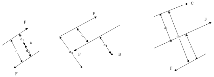
Let moment be MA then


=fd
Now consider the moment of forces about point B which is outside the two forces as shown in figure 28 b
Let the moment be MB then


=Fd
Similarly


=Fd
Thus at any point M =FD
Movement of couple about any point is sam
- Couple is rotated through any angle
- The couple is shifted any other position
- The couple is replaced by another pair of forces whose rotational effect is same.
Transfer of force to parallel position
It will be advantages to resolve a force acting at a point on a body into a force acting at dome other suitable point on body and a couple .In figure 29 a f is a force acting on a body at A

Now it can be shown that F at A main busy solved into force f at b e and couple of magnitude M =F×d where d=perpendicular distance of B from the line of action of F through A.
By applying equal and opposite force f at b system of forces is not disturbed hence system of forces in figure 29( b) is same as system of forces in figure 29 (a).
Now a force f at A and force at b e form a couple of magnitude fd. So figure 29b can be shown in figure 29 c
Thus given force f at a is replaced by force f at B and moment Fd .
Example 22:- Three external forces are acting on l -shaped body as shown in figure 30 determine the equivalent system through point o.
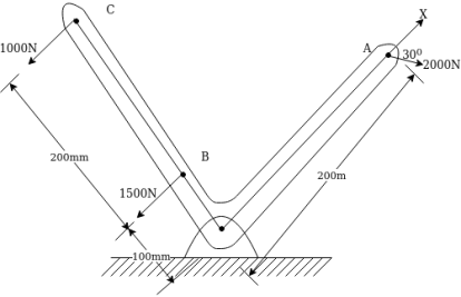
Solution:- equivalent system through point o means
- Resultant of forces system
- Single moment through point o
Resolving forces horizontally

Similarly
Resolving forces vertically

=-1000
Resultant force (R)=
=1260.8513N
Taking moment about point O.

=-650000 N.mm
-ve sign indicate anticlockwise direction of moment.
Example 13:-figure 31 show two vertical forces and couple of movement 2000 Nm acting on horizontal rod which is fix at and A.
- Determine resultant of system
- Determine an equivalent system through A.
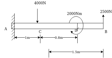
Solution:-All forces are vertical
Resultant ®= -4000+2500
=-1500N
-ve sign indicate force acting downward
Movement about point MA=4000×1+2000-2500×2.5
=-250N.m
-ve sign indicate movement of anticlockwise
As resultant is downward and movement is anticlockwise we can say that resultant is on left side of point A.
Let=X perpendicular distance between resultant force and point A.
From varignon’s theorem
1500×x=250
X=0.1667m
Example 14:-find the resultant of 4 system figure 32 acting on a lamina of equilateral triangular shape
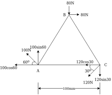
Solution:-Resolving forces horizontally
ΣH=80-120Cos30-1500-100Cos60
=73.9230
=-ve sign indicates that force acting towards left
Resolving forces vertically


-ve sign indicate force acting downwards
Resultant (R)=
=91.1915N
Tan[x=ΣV/ΣH]
x=35.84
Moment about point A= MA=80*50+80*100Sin60+120Sin30*100
=16928.2032N.mm
Applying varignon theorem
Let=x = perpendicular distance between resultant (R )and point A
53.3975*x=16928.2032
X=317.0224mm