UNIT 3
INTRODUCTION TO REFRIFGERATION AND AIR CONDITIONING
Reversing the Carnot cycle does reverse the directions of heat and work interactions. A refrigerator that operates on the reversed Carnot cycle is called a Carnot refrigerator.
The Reversed Carnot Cycle
Reversed Carnot cycle is an ideal refrigeration cycle for constant temperature external heat source and heat sinks. The figure below shows the schematic of a reversed Carnot refrigeration system using a gas as the working fluid along with the cycle diagram on T-s and P-v coordinates. As shown, the cycle consists of the following four processes:
Process 1-2: Reversible, adiabatic compression in a compressor
Process 2-3: Reversible, isothermal heat rejection in a compressor
Process 3-4: Reversible, adiabatic expansion in a turbine
Process 4-1: Reversible, isothermal heat absorption in a turbine
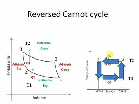
In process 1-2: The gas is Isentropically compressed, and there is no heat flow into or out of the refrigerator.
In process 2-3: Heat is expelled into the sink (e.g. Outside air) isothermally (T2=T3). The amount of heat ejected per unit mass of gas is
QC=T2 (S2−S3).
In process 3-4: The gas is isentropically expanded. The pressure and temperature decrease to P4, T4. Heat transfer at this stage is zero.
In process 4-1: The gas expands isothermally (T4=T1), extracting heat from the source (e.g. Room). This is where the cooling takes place. The heat extracted from the source per unit mass of gas is
QH=T1(S1−S4)=T1(S2−S3)
The work done during the process is simply
W=QH−QC
= T1(S2−S3) - T2 (S2−S3).
= (T1−T2)(S2−S3)
The efficiency of the reverse Carnot cycle is the heat removed from the cold reservoir / the amount of work input:
ηcool=QC / W
ηcool= T2 (S2−S3) / (T1−T2)(S2−S3)
So ηcool = T2 / T1−T2
Coefficient of Performance (COP)
The performance of refrigerators is expressed in terms of coefficient of performance (COP):
Coefficient of performance of the system working on the Reverse Carnot cycle.
C.O.P = Heat absorbed / work done
= qa /qa – qr
= T1( S1 – S3 )/ ( T2 – T1 ) (S1 – S3 )
= T1/ T2 – T1
Reverse Carnot cycle is most efficient between the fixed temperature limits yet no refrigerator could be made using this cycle. This is due to the fact that the isentropic process requires high speed and the isothermal process requires extremely low speed
The reversed Carnot cycle is the most efficient refrigeration cycle operating between two specified temperature levels. It sets the highest theoretical COP.
Numerical on reverse Carnot cycle
Question) A Reverse Carnot cycle for refrigeration absorbs heat at 270K and rejects at 300K. Calculate the Coefficient of performance of this cycle.If the cycle is absorbing 1130kj/min at 270 K. How many kJ work is required per second?
Answer)
T1 = 270 K and T2 = 300 K
As we know that
C.O.P = T1/ T2 – T1
C.O.P = 270 / 300 – 270
C.O.P = 9
Work Require per second
Heat absorbed at 270 K,
Q1 = 1130 kJ/min = 18.83 kJ/s.
As we have discussed above
C.O.P = Heat Absorbed / Work Done
9 = 18.83 / Work Done
Work Done = 2.1 kJ / s
The Refrigerant is the working substance that flows through a refrigerator and is capable of absorbing heat from the source ( which is at a lower temperature) and dissipate the same to the sink (which is a higher temperature than the source) either in the form of sensible heat (as in case of air refrigeration) or in the form of latent heat (as in the case of vapour Refrigeration) is called a refrigerant.
Type of refrigerant – There are two type of refrigerant
- Primary refrigerants (Refrigerants that directly take part in the refrigeration process)
- Secondary refrigerants (refrigerants that are first cooled by the primary refrigerants and then further used for cooling purpose
Classification of primary refrigerants:
1) Halocarbon compounds:
(a) Invented and developed by Mr Charles. Kettering and Dr. Thomas Migley in the year1928.
(b) It also known as “Freon” and contain one or more of three halogens chlorine, fluorine and bromine.
Number | Chemical Name | Chemical Formula |
R-11 | Trichloro Monofluoro Methane | CCl3F |
R-12 | Dichloro Difluoro Methane | CCl2F2 |
R-13 | Monochloro Trifluoro Methane | CClF3 |
R-22 | Monochloro Difluoro Methane | CHClF2 |
R-113 | Trichloro Difluoro Ethane | C2Cl3F3 |
2) Azeotropes:
It Consist of mixtures of different refrigerants which don’t separate into their compounds with the change in pressure or temperature or both. They have fixed thermodynamic properties.
Name | Mixture by weight |
R-500 | 73.8% of R-12 & 26.2% of R-152a |
R-502 | 48.8% of R-22 & 51.2% of R-115 |
R-503 | 40.1% of R-23 & 59.9% of R-13 |
Azeotropic mixture is a mixture of two or more liquids which, when mixed in precise proportion, form a compound having a boiling temperature which is independent of the boiling temperature of the individual liquids.
3) Hydrocarbons:
Most of the organic compounds are considered as refrigerant under this group. Most of them possess satisfactory thermodynamic-properties but are highly flammable.
Number | Chemical Name | Chemical Formula | |
R-50 | Methane | CH4 | |
R-100 | Ethane | CH3CH3 | |
R-290 | Propane | CH3 CH2 CH3 | |
4) Inorganic compounds:
The refrigerants under this group were universally used for all purposes before the introduction of halo-carbon. Refrigerants. Earlier they were used for different purposes due to their inherent thermo-dynamic and physical properties.
Number | Chemical Name | Chemical Formula | Specific use |
R-717 | Ammonia | NH3 | Ice plants |
R-118 | Water | H2O | In steam production system |
R-729 | Air | – | For aeroplanes |
R-744 | Carbon Dioxide | CO2 | For ship refrigeration |
Unsaturated Organic Compounds: Comprising of mainly hydrocarbon group with ethylene and propylene bases.
Number | Chemical Name | Chemical Formula |
R-1120 | Trichloro Ethylene | C2H4Cl4 |
R-1130 | Dichloro Ethylene | C2H4Cl2 |
R-1150 | Ethylene | C2H4 |
R-1270 | Propylene | C3H6 |
SECONDARY REFRIGERANTS
Under many circumstances it is not desirable to carry the heat from the refrigerated space directly as refrigerant, than it is carried by using the secondary refrigerant.
The secondary refrigerant is a liquid which is cooled in the refrigeration machinery room and pumped around the refrigerated.
The main advantage of this arrangement over direct cooling system is as follows:
(1) The primary refrigerant is only present in the machinery space and the risk of loss of leakage is more readily controlled.
(2) Difficulties of oil recovery from the evaporators which are located in the cargo spaces quite a distance away from the compressors are avoided.
(3) The pipelines used for carrying the heat by secondary refrigerant from the source is considerably smaller compared with the pipeline used with direct expansion refrigeration system and this is because the specific volume of the brine is considerably low compared with the specific Volume of the refrigerant vapour. Therefore the pipeline diameter required for secondary refrigerant is considerably lower.
(4) The secondary refrigerant system is more easily controlled to give accurate temperature control. If a manual system, less skilled operators are required. If an automatic system, simpler automatic controls can be used.
(5) Greater flexibility in simultaneously carrying cargoes at different temperatures in different cargo spaces is possible by controlling the amount of brine following to that space.
(6) The use of secondary refrigerant such as brine is also advantageous in Order to keep the coils Researchers have determined that chlorofluorocarbons (CFCs) along with other chlorine and bromine containing compounds have been largely responsible for accelerated depletion of ozone in the earth’s stratosphere.
The commonly used secondary refrigerants are water, sodium chloride brine, and calcium chloride brine. Calcium chloride brine is the commonest secondary refrigerant used for cargo refrigeration, water is used for air conditioning installations (with suitable safeguards to prevent its freezing) and trichloroethylene is used for very less temperature installations such as fishing trawlers.
Refrigerant properties:
Following are the refrigerant properties shown below
1) Low boiling point and Low freezing point.
2) Low specific heat and High latent heat.
3) High critical pressure and temperature
4) Low specific volume to reduce the size of the compressor.
5) High thermal conductivity to compact evaporator and condenser.
6) Non-flammable, non-explosive, non-toxic and non-corrosive.
7) High miscibility with lubricating oil
8) High COP in the working temperature range.
9) Compatible with legal requirement
10) Availability and cost
Vapour compression system: Vapour-compression refrigeration, in which the refrigerant undergoes phase changes, is one of the many refrigeration cycles and is the most widely used method for air-conditioning of buildings and automobiles. It is also used in domestic and commercial refrigerators, large-scale warehouses for chilled or frozen storage of foods and meats, refrigerated trucks and railroad cars, and a host of other commercial and industrial services. Oil refineries, petrochemical and chemical processing plants, and natural gas processing plants are among the many types of industrial plants that often utilize large vapour-compression refrigeration systems.
Working Of Vapour Compression Refrigeration System:
The figure shows the basic components of a vapour compression refrigeration system.
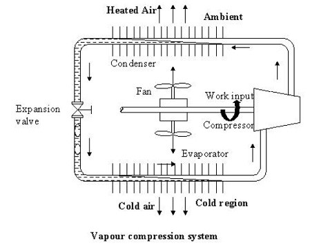
As shown in the figure the basic system consists of an evaporator, compressor, condenser and an expansion valve.
The refrigeration effect is obtained in the cold region as heat is extracted by the vaporization of refrigerant in the evaporator. The refrigerant vapour from the evaporator is compressed in the compressor to a high pressure at which its saturation temperature is greater than the ambient or any other heat sink. Hence when the high pressure, high-temperature refrigerant flows through the condenser, condensation of the vapour into liquid takes place by heat rejection to the heat sink. To complete the cycle, the high-pressure liquid is made to flow through an expansion valve. In the expansion valve the pressure and temperature of the refrigerant decrease. This low pressure and low-temperature refrigerant vapour evaporates in the evaporator taking heat from the cold region. It should be observed that the system operates on a closed cycle. The system requires input in the form of mechanical work. It extracts heat from a cold space and rejects heat to a high-temperature heat sink.
Vapour Compression Cycle -Working Diagram
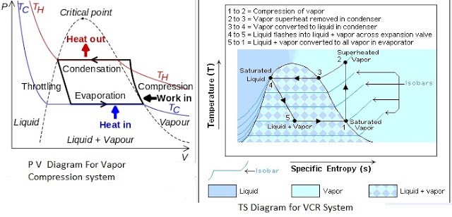
PV And TS Diagram For Vapour Compression System
Most of the modern refrigerators work on this cycle, in its simplest form, there are four fundamental operations required to complete one cycle.
(a) Compression
(b) Condensation
(c) Expansion
(d) Vaporization
a) Compression
The low-pressure Vapour in the dry state is drawn from the evaporator during the suction stroke of the compressor. During compression Stroke, the pressure and temperature increase until vapour temperature is greater than the temperature of condenser cooling medium (air or water)
At point 1 in the diagram, the circulating refrigerant enters the compressor as a saturated vapour. From point 1 to point 2, the vapour is isentropically compressed (i.e., compressed at constant entropy) and exits the compressor as a superheated vapour.
b) Condensation
When the high-pressure refrigerant vapor enters the condenser heat flows from the condenser to the cooling medium thus allowing the vaporized refrigerant to return to the liquid state.
From point 2 to point 3, the vapour travels through part of the condenser which removes the superheat by cooling the vapour. Between point 3 and point 4, the vapour travels through the remainder of the condenser and is condensed into a saturated liquid. The condensation process occurs at essentially constant pressure.
c) Expansion
After condenser the liquid refrigerant is stored in the liquid receiver until needed. From the receiver it passes through an expansion valve where the pressure is reduced sufficiently to allow the vaporization of liquid at a low temperature of about -10°C.
Between points 4 and 5, the saturated liquid refrigerant passes through the expansion valve and undergoes an abrupt decrease of pressure. That process results in the adiabatic flash evaporation and auto-refrigeration of a portion of the liquid (typically, less than half of the liquid flashes).
d) Vaporization
The low-pressure refrigerant vapor after expansion in the expansion valve enters the evaporator or refrigerated space where a considerable amount of heat IS absorbed by it and refrigeration is furnished.
Between points 5 and 1, the cold and partially vaporized refrigerant travels through the coil or tubes in the evaporator where it is vaporized by the warm air (from the space being refrigerated) that a fan circulates across the coil or tubes in the evaporator.
The resulting refrigerant vapour returns to the compressor inlet at point 1 to complete the thermodynamic cycle.
Vapour absorption system:
The vapour absorption refrigeration system comprises of all the processes in the vapour compression refrigeration system like condensation, expansion and evaporation except compression.
In the vapour absorption system the refrigerant used is ammonia, water or lithium bromide. The refrigerant gets condensed in the condenser and it gets evaporated in the evaporator. The refrigerant produces cooling effect in the evaporator and releases the heat to the atmosphere via the condenser.
The major difference between the two systems is the method of the suction and compression of the refrigerant in the refrigeration cycle.
In the vapour compression system, the compressor sucks the refrigerant from evaporator and compresses it to the high pressure. The compressor also enables the flow of the refrigerant through the whole refrigeration cycle.
In the vapour absorption cycle, the process of suction and compression are carried out by two different devices called as the absorber and the generator. Thus the absorber and the generator replace the compressor in the vapour absorption cycle. The absorbent enables the flow of the refrigerant from the absorber to the generator by absorbing it.
Another major difference between the vapour compression and vapour absorption cycle is the method in which the energy input is given to the system. In the vapour compression system the energy input is given in the form of the mechanical work from the electric motor run by the electricity. In the vapour absorption system the energy input is given in the form of the heat. This heat can be from the excess steam from the process or the hot water. The heat can also be created by other sources like natural gas, kerosene, heater etc. though these sources are used only in the small systems
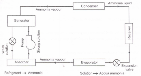
Following are the process involve in vapour absorption system-
1) Condenser: Just like in the traditional condenser of the vapour compression cycle, the refrigerant enters the condenser at high pressure and temperature and gets condensed. The condenser is of water cooled type.
2) Expansion valve or restriction: When the refrigerant passes through the expansion valve, its pressure and temperature reduces suddenly. This refrigerant (ammonia in this case) then enters the evaporator.
3) Evaporator: The refrigerant at very low pressure and temperature enters the evaporator and produces the cooling effect. In the vapour compression cycle this refrigerant is sucked by the compressor, but in the vapour absorption cycle, this refrigerant flows to the absorber that acts as the suction part of the refrigeration cycle.
4) Absorber: The absorber is a sort of vessel consisting of water that acts as the absorbent, and the previous absorbed refrigerant. Thus the absorber consists of the weak solution of the refrigerant (ammonia in this case) and absorbent (water in this case). When ammonia from the evaporator enters the absorber, it is absorbed by the absorbent due to which the pressure inside the absorber reduces further leading to more flow of the refrigerant from the evaporator to the absorber. At high temperature water absorbs lesser ammonia, hence it is cooled by the external coolant to increase it ammonia absorption capacity.
5) Pump: When the absorbent absorbs the refrigerant strong solution of refrigerant-absorbent (ammonia-water) is formed. This solution is pumped by the pump at high pressure to the generator. Thus pump increases the pressure of the solution to about 10bar.
6) Generator: The refrigerant-ammonia solution in the generator is heated by the external source of heat. This is can be steam, hot water or any other suitable source. Due to heating the temperature of the solution increases. The refrigerant in the solution gets vaporized and it leaves the solution at high pressure. The high pressure and the high temperature refrigerant then enters the condenser, where it is cooled by the coolant, and it then enters the expansion valve and then finally into the evaporator where it produces the cooling effect. This refrigerant is then again absorbed by the weak solution in the absorber.
In this system ammonia is used as refrigerant and solution is used is aqua ammonia. Strong solution of aqua ammonia contains as much as ammonia as it can and weak solution contains less ammonia.
The compressor of vapour compressor system is replaced by an absorber, generator, reducing valve and pump. The heat flow in the system at generator, and work is supplied to pump. Ammonia vapours coming out of evaporator are drawn in absorber. The weak solution containing very little ammonia is spread in absorber.
The weak solution absorbs ammonia and gets converted into strong solution. This strong solution from absorber is pumped into generator. The addition of heat liberates ammonia vapour and solution gets converted into weak solution. The released vapour is passed to condenser and weak solution to absorber through a reducing valve. Thus, the function of a compressor is done by absorber, a generator, pump and reducing valve. The simple vapour compressor system is used where there is scarcity of Electricity and it is very useful at partial and full load.
Efrigeration systems that use environment-friendly refriger-
Ants provide a sustainability advantage when compared to
Other refrigerant selections. However, the energy use associated
With refrigeration system operation and the environmental impacts
Associated with its generation and distribution often outweigh the
Choice of refrigerant. To minimize environmental impacts associated
With refrigeration system operation, it is reasonable to evaluate the
Prospects of a clean source of energy
Refrigeration systems that use environment-friendly refrigerants provide a sustainability advantage when compared to other refrigerant selections. However, the energy use associated with refrigeration system operation and the environmental impacts associated with its generation and distributions often outweigh the choice of refrigerant. To minimize environmental impacts associated with refrigeration system operation, it is reasonable to evaluate the prospects of a clean source of energy. Solar refrigerant system is best example for reducing environment pollution.
From a sustainability perspective,
Directly using solar as a primary energy
Source is attractive because of its uni-
Versal availability, low environmental
Impact, and low or no ongoing fuel
Cost. Research has demonstrated that
Solar energy is an ideal source for low-
Temperature heating applications such as
From a sustainability perspective, directly using solar as a primary energy source is attractive because of its universal availability, low environmental impact, and low or no on-going fuel cost.
Research has demonstrated that solar energy is an ideal source for low-temperature heating applications such as space and domestic hot water heating. Solar heating applications are intuitive or natural since, when solar energy is absorbed on a surface, the surface temperature rises, providing a heating potential. The use of solar energy to provide refrigeration is less intuitive.
We review three approaches that use solar energy to provide refrigeration at temperatures below 0°C (32°F). In addition to reviewing the potential technologies, we compare their operating characteristics. We conclude that only one of the three technologies photovoltaic-based vapour compression, is presently a viable solar refrigeration technology.
Photovoltaic Operated Refrigeration Cycle
Photovoltaics (PV) involve the direct conversion of solar
Radiation to direct current (dc) electricity using semiconduct-
Ing materials. In concept, the operation of a PV-powered solar
Refrigeration cycle is simple. Solar photovoltaic panels produce
Dc electrical power that can be used to operate a dc motor,
Which is coupled to the compressor of a vapor compression
Refrigeration system. The major considerations in designing
a PV-refrigeration cycle involve appropriately matching the
Electrical characteristics of the motor driving the compressor
With the available current and voltage being produced by the
PV array
Photovoltaic Operated Refrigeration Cycle Photovoltaic (PV) involves the direct conversion of solar radiation to direct current (dc) electricity using semiconducting materials. In concept, the operation of a PV-powered solar refrigeration cycle is simple. Solar photovoltaic panels produce dc electrical power that can be used to operate a dc motor, which is coupled to the compressor of a vapour compression refrigeration system. The major considerations in designing a PV-refrigeration cycle involve appropriately matching the electrical characteristics of the motor driving the compressor with the available current and voltage being produced by the PV array.

The biggest advantage of using solar panels for refrigeration is the simple construction and high overall efficiency when combined with a conventional vapour compression system.
The rate of electrical power capable of being generated by a PV system is typically provided by manufacturers of PV modules for standard rating conditions, i.e., incident solar radiation of 1,000 W/m2 (10 800 W/ft2) and a module temperature of 25°C (77°F). Unfortunately, PV modules will operate over a wide range of conditions that are rarely as favourable as the rating condition. In addition, the power produced by a PV array is as variable as the solar resource from which it is derived. The performance of a PV module, expressed in terms of its current-voltage and power-voltage characteristics, principally depends on the solar radiation and module temperature.
Whereas solar mechanical refrigeration uses a conventional vapour compression system driven by mechanical power that is produced with a solar-driven heat power cycle. The heat power cycle usually considered for this application is a Rankine cycle in which a fluid is vaporized at an elevated pressure by heat exchange with a fluid heated by solar collectors.
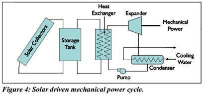
A storage tank can be included to provide some high temperature thermal storage. The vapour flows through a turbine or piston expander to produce mechanical power, as shown in Figure The fluid exiting the expander is condensed and pumped back to the boiler pressure where it is again vaporized
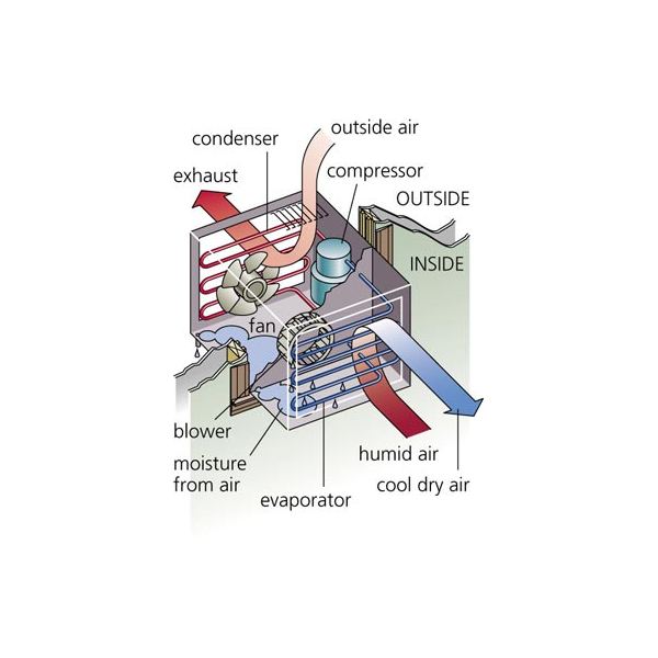
Window air conditioner is sometimes referred to as room air conditioner as well. It is the simplest form of an air conditioning system and is mounted on windows or walls. It is a single unit that is assembled in a casing where all the components are located.
This refrigeration unit has a double shaft fan motor with fans mounted on both sides of the motor. One at the evaporator side and the other at the condenser side. The evaporator side is located facing the room for cooling of the space and the condenser side outdoor for heat rejection. There is an insulated partition separating this two sides within the same casing.
Front Panel
The front panel is the one that is seen by the user from inside the room where it is installed and has a user interfaced control be it electronically or mechanically. Older unit usually are of mechanical control type with rotary knobs to control the temperature and fan speed of the air conditioner.
The newer units come with electronic control system where the functions are controlled using remote control and touch panel with digital display.
The front panel has adjustable horizontal and vertical (some models) louvers where the direction of air flow are adjustable to suit the comfort of the users. The fresh intake of air called VENT (ventilation) is provided at the panel in the event that user would like to have a certain amount of fresh air from the outside.
The mechanical type is usually lower in price compared to the electronic type. If you just want to cool the room and are not too particular about aesthetic or additional functions, the mechanical type will do the work.
Indoor Side Components
The indoor parts of a window air conditioner include:
- Cooling Coil with an air filter mounted on it. The cooling coil is where the heat exchange happens between the refrigerant in the system and the air in the room.
- Fan Blower is a centrifugal evaporator blower to discharge the cool air to the room.
- Capillary Tube is used as an expansion device. It can be noisy during operation if installed too near the evaporator.
- Operation Panel is used to control the temperature and speed of the blower fan. A thermostat is used to sense the return air temperature and another one to monitor the temperature of the coil. Type of control can be mechanical or electronic type.
- Filter Drier is used to remove the moisture from the refrigerant.
- Drain Pan is used to contain the water that condensate from the cooling coil and is discharged out to the outdoor by gravity.
The outdoor side parts include:
- Compressor is used to compress the refrigerant.
- Condenser Coil is used to reject heat from the refrigeration to the outside air.
- Propeller Fan is used in air-cooled condenser to help move the air molecules over the surface of the condensing coil.
- Fan Motor is located here. It has a double shaft where the indoor blower and outdoor propeller fan are connected together.
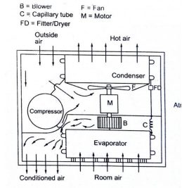
The low pressure and low temperature refrigerant vapour from evaporator is sucked by compressor. The compressor compresses the vapour to high pressure and high temperature and discharges to the condenser. On the condenser the refrigerant vapour condenses by dissipating heat to the cooling medium (air) the liquid refrigerant coming out of condenser passes through filter, dryer into capillary tube where it is again throated back to the evaporated pressure. The low pressure low temp liquid refrigerant then flows to evaporator which it boil off by extracting heat from air to be circuited to the conditioned space.
Air usually contains moisture and this air-moisture mixture varies from place to place and with time. The pressures and temperatures that exist at the time influence the behaviour of this air moisture mixture. Increases in pressure or, more effectively, decreases in temperature may result in condensation of the water vapour to form condensation.
The vast majority of humidity variations occurring underground are caused by the evaporation of liquid water or the condensation of water vapour.
Psychometric is the study of moisture in air under given conditions and during different temperature-humidity processes.
.
Pressure, Temperature, and Humidity
When a small amount of water was introduced into a vacuum space, some of it would evaporate and it would build up a certain pressure in the space, depending purely on the ruling temperature. The higher the temperature, the more moisture it can hold, just like in a hot summer day, and this pressure is called vapour pressure. If the space contains as much water vapour as it can hold at the existing temperature it is said to be saturated with water vapour at that temperature. The behaviour of air-moisture mixture can best be explained by Dalton's Law.
When there is sufficient water present to allow the vapour pressure to build up to the full amount applicable at that temperature, the space is saturated with water vapour at that temperature. On the other hand, if there is insufficient water present, the pressure will not build up to this full pressure.
The ratio of the actual vapour pressure to the saturation vapour pressure at the same temperature is called relative humidity, while the ratio of the actual mass of water vapour that could be contained at saturation is called percentage humidity or specific humidity (W), measured in grains/lb
.
The density of this air-vapour mixture can be expressed as,
ρb = ρa + ρv in lb/ft3 or kg/m3
Where ρb is density for moist air, ρa is density for dry air, ρv is density for water vapour, ρsat is density of saturated air.
Following are the different psychometric properties:
1. Dry air: It is a mixture of oxygen (20.91%) and nitrogen (79.09 %) by volume.
2. Moist air: It is mixture of dry air and water vapour.
3. Saturated air: Air which have maximum amount of water vapour.
4. Dry bulb temp (DBT): It is temperature of air recorded by ordinary thermometer with clean and dry sensing elements. (td or dbt)
5. Wet bulb temp (WBT): It is temperature of air recorded by thermometer when its bulb is covered with a wet cloth. (tw or wbt)
6. Wet bulb depression: It is the difference between dry bulb temp and wet bulb temp.
7. Dew point temp.: It is the temperature of air recorded by thermometer when the moisture present in the air begins to condensed.
8. Dew point depression: It is difference between dry bulb temperature and dew point temperature of air.
9. Specific humidity or Humidity ratio (W): It is defined as mass of water vapour in unit mass of dry air.
w= mv/ma
10. Degree of saturation or Percentage humidity: It is the ratio of mass of water vapour in unit mass of dry air to the mass of water vapour in the same mass of dry air when it is saturated at the same temperature.
= w/ws
11. Relative humidity: It is the ratio of actual mass of water vapour (mv) in a given volume of moist air to mass of water vapour (ms) in the same volume of saturated air at the same temp and pressure.
= mv/ms
12. Enthalpy of moist air: (H) It is total heat contained in moist air. It is sum of sensible heat and latent heat of moist air.
Refrigeration deals with cooling of bodies or fluids to temperatures lower than those of surroundings. This involves absorption of heat at a lower temperature and rejection to higher temperature of the surroundings.
Application of refrigeration
1. Domestic refrigeration.
2. Commercial refrigeration.
3. Industrial refrigeration.
4. Marine and transportation refrigeration
5. Cold treatment of metals in the manufacture of precision parts, cutting tools to improve dimensional accuracy, hardness, wear resistance and tool life.
6. For storage of blood plasma, tissues, etc.
7. For manufacture and storage of drugs.
8. in surgery for local anaesthesia.
9. In construction for setting of concrete and for freezing wet soil to facilitate excavation.
10. Desalination of water by freezing. Manufacture of ice, ice cubes, flakes, etc.
11. For storage of vaccines, medicines in remote and rural areas.
As the name implies, air conditioning is concerned with the condition of the air in some designated area or space this usually involves control not only of the space temperature but also of space humidity and air motion, along with the filtering and cleaning of the air.
1) Comfort Air Conditioning
2) Industrial Air Conditioning
3) Food Preservation
4) Industrial, such as in textiles, printing, manufacturing, photographic, computer rooms, power plants, vehicular etc.
5) Comfort – commercial, residential etc