UNIT 4
ENERGY SOURCES AND POWER PLANTS
All things that are useful to us are called resources. Air, water, land, soil, forest etc. are all resources.
Resources are useful raw materials that we get from nature. These are naturally occurring materials. They are useful for us in many ways, and we keep developing new ways to use them or convert them into useful things.
Natural resources are valuable to us. The broadest classification of resources is done on the basis of their replenishing ability. Let us take a look, at these two classifications.
Renewable resources
Non Renewable resources
Renewable energy – It often referred to as clean energy, comes from natural sources or processes that are constantly replenished. For example, sunlight or wind keep shining and blowing, even if their availability depends on time and weather.
While renewable energy is often thought of as a new technology, harnessing nature’s power has long been used for heating, transportation, lighting, and more. Wind has powered boats to sail the seas and windmills to grind grain. The sun has provided warmth during the day and helped kindle fires to last into the evening. But over the past 500 years or so, humans increasingly turned to cheaper, dirtier energy sources such as coal and non-renewable source.
When talking about classification of resources, we will first see the renewable resources. Renewable resources are those resources that can be replenished or renewed naturally over time. Air, water, wind, solar energy etc. are all renewable resources. Renewable resources can be easily renewed by nature.
Following are the some renewable source energy examples given below:
1. Solar energy
Sun is a big source of energy. The energy that we get from the Sun is called solar energy. The entire natural phenomenon like the flowing of wind, water cycle, photosynthesis etc is possible only due to solar energy. Now a day, solar energy is being used to cook food with the help of solar cookers, heat water, light streets, pump water for irrigating fields etc
2. Hydro-Energy
Water is important natural resources. All living organisms need water to live. Humans need water for many purposes such as drinking, cleaning, cooking and for growing crops. Water flowing into the river or water stored in a dam is sources of hydro energy. The Simple method to use hydro energy is to convert it into electrical energy.
3. Wind energy
Winds are constantly being created in nature. The windmill is a source of electrical energy. These windmills are generally established only at places where most of the days in a year experience strong winds. The energy from this wind is used for grinding grain, pumping water and to produce electricity. In India, many windmills have been set up in different places such as Tamil Nadu, Maharashtra, Rajasthan, Kerala, West Bengal and Gujarat.
4. Biogas
Biogas is a type of fuel which is a mixture of gases such as methane, carbon dioxide, hydrogen etc which is obtained by decomposition of animal and plant wastes like animal dung, with the help of micro-organisms in the presence of water. It is used as fuel in gas stove especially in rural areas.
5. Wood
Wood is an ancient and traditional source of energy. It is mainly a mixture of many carbohydrate compounds. Wood is used to cook food. It leads to deforestation and pollutes air also. In India, still in many villages, they use wood chullas to cook food every day. While having ill effects on the environment, it is also harmful to human health
6. Hydrogen
It is a good source of energy because it does not create pollution and produce maximum energy on burning. Hydrogen has the potential to be the answer to all our energy and fuel troubles. Technology is currently being developed to fully utilize hydrogen efficiency.
7. Alcohol
Alcohol has many commercial and medical purposes. It can use for producing energy. It can be obtained while making sugar from sugarcane. Thus it is a very cheap source of energy. A mixture of petrol and alcohol is being used as a fuel in automobiles. This mixture is called ‘Gasohol’.
Non Renewable resources
The other classification of resources is non-renewable resources. Non-renewable resources are those natural resources that are available in limited quantity. These resources cannot be renewed or replenished in short duration. Therefore they are also known as exhaustible resources.
The advantage of these non-renewable resources is that power plants that use them are able to produce more power on demand. The non-renewable energy resources are:
Examples- coal, natural gas, petroleum etc.
1. Fossil fuel
Fossil fuels like coal and petroleum are non-renewable resources. They are found deep inside the earth and are made by natural processes over many centuries. Their quantity is limited and they take thousands of years to get renewed. Example of fossil fuels is coal, petroleum, natural gas etc.
Coal: It is also known as black diamond. Coal is used as a fuel, to generate electricity, and in factories and steam engines.
Natural gas: Natural gas is used as a fuel called Compressed Natural Gas or CNG. Some wells dug into the earth produce only natural gas. Natural gases are a good alternative to petrol and diesel and it is used as Compressed Natural Gas. It burns easily and produces a lot of heat. It is a good source of hydrogen.
Petroleum: Petroleum is also known as mineral oil or crude oil. This liquid mineral is refined to make fuels such as petrol, diesel, cooking gas and kerosene. Plastic, cosmetics, and lubricants are also products of petroleum. It is found deep inside the Earth or under the sea floor. It is taken out by drilling wells deep into the Earth or under the seabed.
2. Nuclear energy
In the classification of resources, nuclear energy is classified as non-renewable. The fuel used for nuclear energy is generally uranium, which is in a limited supply. So we classify it as non-renewable. Production of electricity from nuclear energy does not release carbon dioxide. Thus, use of nuclear energy is safe for the environment.
The solar flat-plate collectors are probably the most fundamental and most studied technology for solar-powered domestic hot water systems. The overall idea behind this technology is pretty simple. The Sun heats a dark flat surface, which collects as much energy as possible, and then the energy is transferred to water, air, or other fluid for further use.
For most residential and small commercial hot water applications, the solar flat plate collector tends to be more cost effective due to their simple design, low cost, and relatively easier installation compared to other forms of hot water heating systems. Also, solar flat plate collectors are more than capable of delivering the necessary quantity of hot water at the required temperature.
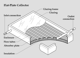
These are the main components of a typical flat-plate solar collector:
- Black surface - absorbent of the incident solar energy
- Glazing cover - a transparent layer that transmits radiation to the absorber, but prevents radioactive and convective heat loss from the surface
- Tubes containing heating fluid to transfer the heat from the collector
- Support structure to protect the components and hold them in place
- Insulation covering sides and bottom of the collector to reduce heat losses.
Some advantages of the flat-plate collectors are that they are:
- Easy to manufacture
- Low cost
- Collect both beam and diffuse radiation
- Permanently fixed (no sophisticated positioning or tracking equipment is required)
- Little maintenance
If we need more energy for use, we have two options. The first option is to increase the system scale (for example by increasing the number of receivers). In other words, we have to expand the plant area, which would involve additional cost for construction, service, maintenance, and may require additional land, more materials, etc. It has been done to some extent, but sometimes it is not a sufficient measure to meet the energy demands, especially if land area is a constraint.
The second option is to concentrate the radiation flux. This can be achieved by placing a concentrator (usually some kind of optical device) between the light source (sun) and the receiver. By common terminology, a solar collector is a sunlight processing system that includes a concentrator and a receiver in its setup; it is also characterized by aperture - the cross sectional area through which sunlight accesses the system.
The most common concentrators are reflectors (mirrors) and refractors (lenses), which modify and redirect the incident sunlight beam. The design of the concentrating optics varies. Some of the examples of concentrating collectors, which involve diversely shaped mirrors are parabolic and cylindrical collector. .A solar collector that uses reflective surfaces to concentrate sunlight onto a small area, where it is absorbed and converted to heat or, in the case of solar photovoltaic (PV) devices, into electricity.
Concentrators can increase the power flux of sunlight hundreds of times. The principal types of concentrating collectors include: compound parabolic, parabolic trough, fixed reflector moving receiver, fixed receiver moving reflector, Fresnel lens, and central receiver. A PV concentrating module uses optical elements (Fresnel lens) to increase the amount of sunlight incident onto a PV cell. Concentrating PV modules/arrays track the sun and use concentrating devices to reflect direct sunlight onto the solar cell to produce electricity directly. Concentrating solar collectors in Concentrated Solar Power (CSP) facilities concentrate sunlight onto a receiver where it heats a heat transfer fluid that subsequently exchanges its absorbed heat to water to produce steam to power a steam turbine-generator (STG) to produce electricity.
The parabolic cylinder solar collector is another type of solar thermal collector. This type of solar panel used in solar thermal installations uses parabolic cylinders to concentrate all the solar radiation in a point. Instead of heliostats, this type of collector employs parabolic trough mirrors. For the focus of the parabola passes a pipe that receives the concentrated rays of the Sun, where the fluid is heated, usually thermal oil. Currently the fluid reaches temperatures close to 400º C.
The collectors are formed by pipes with a selective coating that run longitudinally through the collector and act as an absorber. These pipes receive the solar radiation reflected by the curved walls that surround them, thus achieving a higher amount of energy per unit area of absorber.
Therefore, this type of collectors can be used both to produce sanitary hot water and to support heating or to supply cold equipment by adsorption or absorption. Parabolic solar collector collects the radiant energy emitted from the sun and focuses it at a point. Parabolic trough collectors are the low cost implementation of concentrated solar power technology that focuses incident sun light on to a tube filled with a heat transfer fluid.
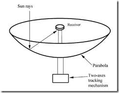
A Schematic diagram of a typical concentrating collector is shown in fig. The collector consists of a concentrator and a receiver. The concentrator shown is a mirror reflector having the shape of a cylindrical parabola. It focuses the sunlight on to its axis where it is absorbed on the surface of the absorber tube and transferred to the fluid flow through it.
A concentric glass cover around the absorber tube helps in reducing the convective and radioactive losses to the surroundings. In order that the sun’s rays should always be focussed on to the absorber tube, the concentrator has to be rotated. This movement is called tracking in the case of cylindrical parabolic concentrators, rotation about a single axis is generally required. Fluid temperatures up to around 50000C can be achieved in cylindrical parabolic focussing collector system.
The main components of a parabolic cylinder solar collector are:
The metallic structure to give rigidity to the whole.
The parabolic trough reflector: The function of the parabolic trough receiver is to concentrate the solar radiation on the absorber tube. For this purpose, it is constructed with reflective materials. At present the most used support media are metal sheet, glass and plastic.
The absorber tube: The absorber tube consists of two concentric tubes separated by a vacuum layer. The interior, through which circulates the fluid that is heated is metal and the outside of glass.
The working fluid that circulates through the inner tube is different according to the technology.
The tracking system of the Sun: The most common tracking system consists of a device that turns the parabolic trough reflectors of the collector around an axis, in this way it is possible to maximize the capture of solar radiation and optimize the angle of incidence.
A photovoltaic (PV) cell is an energy harvesting technology, that converts solar energy into useful electricity through a process called the photovoltaic effect. There are several different types of PV cells which all use semiconductors to interact with incoming photons from the Sun in order to generate an electric current. The Photovoltaic cell is the semiconductor device that converts the light into electrical energy. The voltage induces by the PV cell depends on the intensity of light incident on it.
The name Photovoltaic is because of their voltage producing capability The electrons of the semiconductor material are joined together by the covalent bond. The electromagnetic radiations are made of small energy particles called photons. When the photons are incident on the semiconductor material, then the electrons become energised and starts emitting.
The energises electron is known as the Photoelectrons. And the phenomenon of emission of electrons is known as the photoelectric effect. The working of the Photovoltaic cell depends on the photoelectric effect.
Construction of Photovoltaic Cell
The semiconductor materials like arsenide, indium, cadmium, silicon, selenium and gallium are used for making the PV cells. Mostly silicon and selenium are used for making the cell.
Consider the figure below shows the constructions of the silicon photovoltaic cell. The upper surface of the cell is made of the thin layer of the p-type material so that the light can easily enter into the material. The metal rings are placed around p-type and n-type material which acts as their positive and negative output terminals respectively.
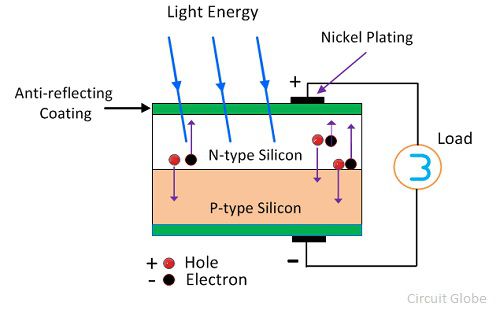
The multi-crystalline or monocrystalline semiconductor material makes the single unit of the PV cell. The mono-crystal cell is cut from the volume of the semiconductor material. The multicells are obtained from the material which has many sides.
The output voltage and current obtained from the single unit of the cell is very less. The magnitude of the output voltage is 0.6v, and that of the current is 0.8v. The different combinations of cells are used for increasing the output efficiency. There are three possible ways of combining the PV cells.
How Solar Cell Install on the Solar Power Plant?
Maximum power point tracker, inverter, charge controller and battery are the name of the apparatus used for converting the radiation into an electrical voltage.
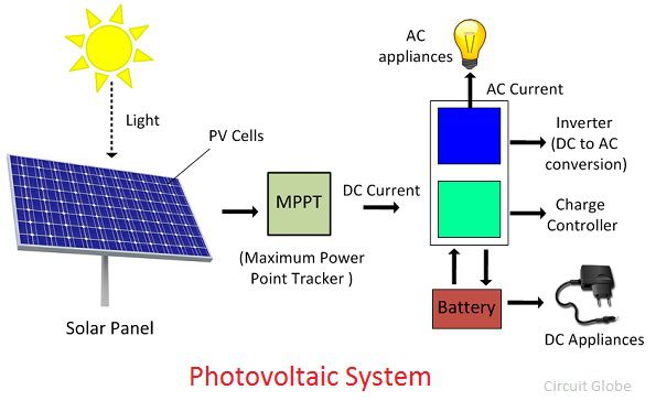
Maximum Power Point Tracker – It’s a special kind of digital tracker that follows the location of the sun. The efficiency of the PV cell depends on the intensity of sunlight fall on it. The power of the sun varies with the time because of the movement of the earth. So for absorbing the maximum light, the panel needs to be moved along with the sun. Thereby the maximum power point tracker is used with the solar panel.
Charge Controller – The charge controller regulates the voltage drawn from the panel. It also protects the battery from the overcharging or overvoltage.
Inverter – The inverter converts the direct current into the alternating current and vice versa. The conversion is essential because some of the appliances require ac supply for their work.
Wind energy is a form of solar energy. Wind energy (or wind power) describes the process by which wind is used to generate electricity. Wind turbines convert the kinetic energy in the wind into mechanical power. A generator can convert mechanical power into electricity. Mechanical power can also be utilized directly for specific tasks such as pumping water.
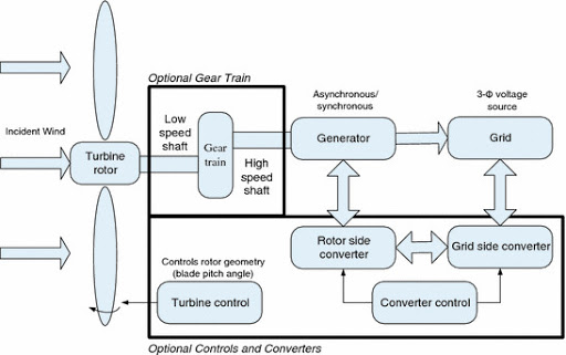
Wind is caused by the uneven heating of the atmosphere by the sun, variations in the earth's surface and rotation of the earth. Mountains, bodies of water, and vegetation all influence wind flow patterns.
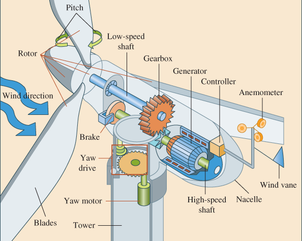
Wind turbines convert the energy in wind to electricity by rotating propeller-like blades around a rotor. The rotor turns the drive shaft, which turns an electric generator. Three key factors affect the amount of energy a turbine can harness from the wind: wind speed, air density, and swept area.
Equation for Wind Power
P = ½ (pAV3)
P= density
Wind speed
The amount of energy in the wind varies with the cube of the wind speed, in other words, if the wind speed doubles, there is eight times more energy in the wind ( 23 = 2 x 2 x 2 = 8).Small changes in wind speed have a large impact on the amount of power available in the wind.
Density of the air
The more dense the air, the more energy received by the turbine. Air density varies with elevation and temperature. Air is less dense at higher elevations than at sea level, and warm air is less dense than cold air. All else being equal, turbines will produce more power at lower elevations and in locations with cooler average temperatures.
Swept area of the turbine
The larger the swept area (the size of the area through which the rotor spins), the more power the turbine can capture from the wind. Since swept area is A = pi x r2 where r = radius of the rotor, a small increase in blade length results in a larger increase in the power available to the turbine.
Wind energy benefits
1) Renewable energy
2) Inexhaustible
3) Not pollutant
4) Reduces the use of fossil fuels
5) Reduces energy imports
6) Creates wealth and local employment
7) Contributes to sustainable development
Humans have been harnessing the energy of river currents for centuries, using water wheels spun by rivers initially to process grains and cloth. Today, hydropower provides about 16% of the world's electricity, generating power.
Hydropower became an electricity source in the late 19th century, a few decades after British-American engineer James Francis developed the first modern water turbine.
A typical hydroelectric plant is a system with three parts: a power plant where the electricity is produced, a dam that can be opened or closed to control water flow, and a reservoir where water is stored. The water behind the dam flows through an intake and pushes against blades in a turbine, causing them to turn. The turbine spins a generator to produce electricity.
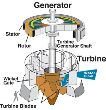
The amount of electricity that can be generated depends on how far the water drops and how much water moves through the system. The electricity can be transported through long-distance electric lines to homes, factories, and businesses. Other types of hydropower plants make use of the flow through a waterway without a dam.
Hydropower plants capture the energy of falling water to generate electricity. A turbine converts the kinetic energy of falling water into mechanical energy. Then a generator converts the mechanical energy from the turbine into electrical energy.
Hydroplants range in size from "micro-hydro’s" that power only a few homes to giant dams like Hoover Dam that provide electricity for millions of people.
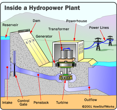
Here are the basic components of a conventional hydropower plant:
- Dam - Most hydropower plants rely on a dam that holds back water, creating a large reservoir. Often, this reservoir is used as a recreational lake, such as Lake Roosevelt at the Grand Coulee Dam in Washington State.
- Intake -Gates on the dam open and gravity pulls the water through the penstock, a pipeline that leads to the turbine. Water builds up pressure as it flows through this pipe.
- Turbine - The water strikes and turns the large blades of a turbine, which is attached to a generator above it by way of a shaft. The most common type of turbine for hydropower plants is the Francis Turbine, which looks like a big disc with curved blades. A turbine can weigh as much as 172 tons and turn at a rate of 90 revolutions per minute (rpm.
- Generators - As the turbine blades turn, so do a series of magnets inside the generator. Giant magnets rotate past copper coils, producing alternating current (AC) by moving electrons.
- Transformer - The transformer inside the powerhouse takes the AC and converts it to higher-voltage current.
- Power lines - Out of every power plant come four wires: the three phases of power being produced simultaneously plus a neutral or ground common to all three.
- Outflow - Used water is carried through pipelines, called tailraces, and re-enters the river downstream.
The water in the reservoir is considered stored energy. When the gates open, the water flowing through the penstock becomes kinetic energy because it's in motion. The amount of electricity that is generated is determined by several factors. Two of those factors are the volume of water flow and the amount of hydraulic head. The head refers to the distance between the water surface and the turbines. As the head and flow increase, so does the electricity generated. The head is usually dependent upon the amount of water in the reservoir.
A plant designed to convert the heat from the combustion of a fuel into mechanical energy by means of steam. Mechanical energy is generally not the end product of a steam power plant but is transformed by electric generators into electric power, which is then transmitted to consumers; this type of steam power plant is called a steam electric power plant.
When steam is produced in an atomic steam-generating plant, the plant is called an atomic power plant or an atomic electric power plant.
Steam power plants consist of one or a group of steam boilers and one or more steam power sources (steam engines or steam turbines) with auxiliary mechanisms, apparatus, and instruments. The simplest steam power plant is the steam power unit, which is composed of a fire-tube boiler on which a piston steam engine is mounted. High-power steam power plants consist of steam boilers and steam turbines with condensing equipment.
The modern trend is to design steam power plants in boiler-turbine units (with power ratings of 300 megawatts or more) that are not interconnected for steam and water. This makes it possible to use short steam pipes with a minimum number of fittings, which is very important with high steam parameters (pressure to 24 mega newton’s per sq m [240 kilograms-force per sq cm]) and temperatures of 570°C and above.
Some of the steam generated in a steam power plant is often used for domestic or industrial purposes, such as heating, cooking, and drying. Steam power plants are used on riverboats and oceangoing vessels (steamships), as well as in railroad transportation (steam locomotives) and, occasionally, in steam automobiles.
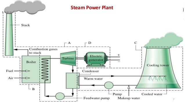
A steam power plant consists of a boiler, steam turbine and generator, and other auxiliaries. The boiler generates steam at high pressure and high temperature. The steam turbine converts the heat energy of steam into mechanical energy. The generator then converts the mechanical energy into electric power.
Our highly efficient and environmental friendly power plants will contribute to the stable supply of electrical power and reduction of environmental impact.
Biogas is a type of biofuel that is naturally produced from the decomposition of organic waste. When organic matter, such as food scraps and animal waste, break down in an anaerobic environment (an environment absent of oxygen) they release a blend of gases, primarily methane and carbon dioxide. Because this decomposition happens in an anaerobic environment, the process of producing biogas is also known as anaerobic digestion.
Anaerobic digestion is a natural form of waste-to-energy that uses the process of fermentation to breakdown organic matter. Animal manure, food scraps, wastewater, and sewage are all examples of organic matter that can produce biogas by anaerobic digestion. Due to the high content of methane in biogas (typically 50-75%) biogas is flammable, and therefore produces a deep blue flame, and can be used as an energy source. Biogas or gobar gas is a combustible gas. It is produced through the anaerobic breakdown of waste biomass.
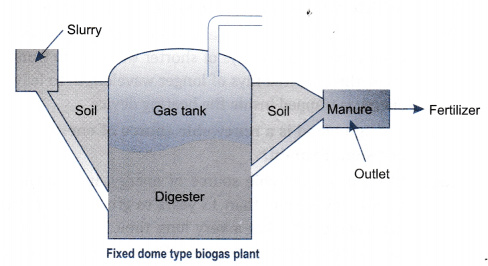
The biogas plant consists of the following parts:-
1) Inlet or charge pit:- for passage of slurry into the digester. The raw material used is cattle dung, farm refuse, and organic waste.
2) Digester: - cylindrical tank which is airtight, above which is present a floating gas holder of metal with an outlet of gas and pit for removal of sludge. Here the organic wastes get solubilized into simpler substances called monomers (solubilisation). Monomers change to organic acid by fermenting microbes (acidogenesis). Organic acid mostly formed is acetic acid. Methanogens become active and act on components of microbial digestion and form methane gas (methanogenesis).
3) Outlet:- consists of sludge which is used as manure.The methane gas formed in this process is used for cooking and lighting.
The advantages of biogas:
- Non-polluting: Biogas burns without smoke; hence no harmful gas such as CO2, CO, NO2, and SO2 are evolved.
- Reduces Landfills: The slurry produced after the production of biogas is used as manure in fields. The method of disposal is safe and efficient and hence no space is wasted in the form of landfills.
- Cheaper technology: Biogas plants require very little installation cost and become self-sufficient in a span of 3-4 months.
- Generates employment: Work opportunity for thousands of people is created, especially in rural areas.
- Renewable source of energy: It is considered as a renewable source of energy. Because the production is dependent on the generation of waste which is an endless process.
- Source of clean and inexhaustible energy
- Generates electricity and heat
- Guarantees energy autonomy
- Enhance waste and by-products
Disadvantages of Biogas
- Not efficient enough on a large scale: Since it is difficult to enhance the efficiency of biogas, it is not economically viable to use biogas on a large scale.
- Contains impurities: It contains many impurities which are difficult to be controlled even after rounds of purification. Biogas when compressed, to be used as fuel, proves to be highly corrosive to the container
- Unstable and hazardous: When methane comes in contact with oxygen it reacts violently to produce carbon dioxide. The highly inflammable nature of methane makes it prone to explosions.
Biodiesel is an alternative fuel similar to conventional or ‘fossil’ diesel. Biodiesel can be produced from straight vegetable oil, animal oil/fats, tallow and waste cooking oil. The process used to convert these oils to Biodiesel is called Trans esterification. This process is described in more detail below. The largest possible source of suitable oil comes from oil crops such as rapeseed, palm or soybean. In the UK rapeseed represents the greatest potential for biodiesel production. Most biodiesel produced at present is produced from waste vegetable oil sourced from restaurants, chip shops, industrial food producers such as Birdseye etc. Though oil straight from the agricultural industry represents the greatest potential source it is not being produced commercially simply because the raw oil is too expensive. After the cost of converting it to biodiesel has been added on it is simply too expensive to compete with fossil diesel. Waste vegetable oil can often be sourced for free or sourced already treated for a small price. (The waste oil must be treated before conversion to biodiesel to remove impurities). The result is Biodiesel produced from waste vegetable oil can compete with fossil diesel. More about the cost of biodiesel and how factors such as duty play an important role can be found here.
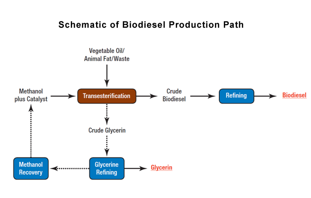
Biodiesel is made through a chemical process called transesterification whereby the glycerine is separated from the fat or vegetable oil. The process leaves behind two products – methyl esters and glycerine.
Methyl esters is the chemical name for biodiesel and glycerine is used in a variety of products, including soap.
Biodiesel can be made from nearly any feedstock (raw material) that contains adequate free fatty acids. Most of U.S. Biodiesel production uses raw vegetable oils, used cooking oils, yellow grease, and animal fats as feedstocks for transesterification. Vegetable oils are the main feedstocks for U.S. Biodiesel production. Other feedstocks for biodiesel production include waste animal fats from processing plants and used/recycled cooking oil and yellow grease from restaurants.