UNIT 5
MECHANICAL POWER TRANSMISSION AND ENERGY CONVERSION DEVICES
CONTENT
The belt or ropes are used to transmit power from one shaft to another by means of pulleys which rotate at the same speed or at different speed.
The amount of power transmission depends upon the following factors:
- Velocity of the belt.
- The tension under which the belt is placed on the pulleys.
- He arc of contact between the belt and the smaller pulley.
- Selection of belt drive.
Selection of belt drive: Following are the various important factors upon which the selection of belt drive depends.
- Speed of the driving and driven shaft
- Speed reduction ratio
- Power to be transmitted
- Centre distance between the shaft
- Positive drive requirements
- Shaft layout
- Speed available
- Service conditions.
TYPE OF BELT DRIVES: The belt drive usually classified into following 3 groups:
1- Light drives- These are used to transmit small powers at belt speeds up to about 10 m/s as in agricultural machines and small machines tools.
2- Medium drives- These are used to transmit medium powers at belt speeds over 10 m/s but up to 22 m/ s as in machine tools.
3- Heavy drives- These are used to transmit large powers at belt speeds above 22 m/s as in compressors and generators.
TYPES OF BELTS: Though there are many types of belts used these days, yet the following important belt drive shown below.
1) Flat belt drive – This belt is mostly used in factories and workshops, where a moderate amount of power is to be transmitted, from one pulley to another when two pulleys are not more than 8 metres apart.
2) V-belts- This belt is mostly used in factories and workshops, where a moderate amount of power is to be transmitted, from one pulley to another when two pulleys are very near to each other.
3) Circular belt or rope- This belt is mostly used in factories and workshops, where a great amount of power is to be transmitted, from one pulley to another when two pulleys are more than 8 metres apart.

FLAT BELT DRIVE: There are different type of flat belt drive which used in factories and workshop, some are given below:
- Open belt drive.
- Cross belt drive.
- Stepped or cone pulley or speed cone drive.
- Fast and loose pulleys.
- Jockey pulley drive or belt drive with idler pulley
- Compound Belt Drive System
- Open Belt Drive:
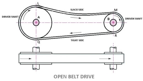
- In these types of belt drive, the belt is employing when the two parallel shafts have to rotate in the same direction.
- When the shafts are far apart, the lower side of the belt should be the tight side and the upper side must be the slack side.
- This is because, when the upper side becomes the slack side, it will sag due to its own weight and thus increase the arc of contact.
LENGTH OF OPEN BELT DRIVE FORMULA:
= π (r1 + r2) + 2x + (r1 – r2)2 /x ……………. (In terms of pulley radii)
= π/2 (d1 + d2) + 2x + (d1 – d2)2/ 4x ……….… (In terms of pulley diameters)
2. Cross Belt Drive
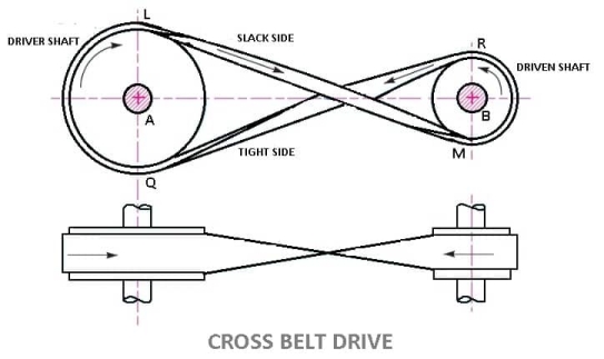
- In this types of belt drives, the belt is employing when two parallel shafts have to rotate in the opposite direction. At the junction where the belts cross, it rubs against itself and wears off.
- To avoid excessive wear, the shafts must be placed at a maximum distance from each other and operated at very low speeds.
LENGTH OF CROSS BELT DRIVE
= π (r1+r2) + 2x + (r1+r2)2 /x …………… (In terms of pulley radii)
= π/2(d1+d2) +2x + (d1 + d2)2/ 4x …………(in terms of pulley diameters)
3. Stepped or Cone Pulley or Speed Cone Drive
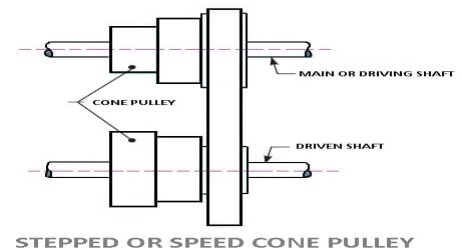
- This types of belt drives are used when the speed of the driven shaft is to be changed very frequently as in the case of machine tools such as lathe, drilling machine, etc.
- A stepped cone pulley is an integral casting having three or number of pulleys of different sizes one adjacent to the other as shown in fig.
- One set of stepped cone pulley is mounted in reverse on the driven shaft. An endless belt will be wrapped around one pair of pulleys.
- By shifting the belt from one pair of pulleys to the other, the speed of the driven shaft can be varied.
- The diameter of the driving and driven pulleys is such that the same belt will operate when shifted on different pairs of pulleys.
4. Fast and Loose Pulley Drive
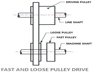
- This types of belt drives are used when the driven or machine shaft is to be started or stopped whenever desired without interfering with the driving shaft.
- A pulley which is keyed to the machine shaft is called a fast pulley and run at the same speed as that of the machine shaft.
- A loose pulley runs freely over the machine shaft and is incapable of transmitting any power.
- When the driven shaft is required to be stopped, the belt is pushed on to the loose pulley by means of a sliding bar having belt forks.
5. Jockey Pulley Drive or belt drive with idler pulleys:
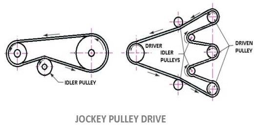
- In an open belt drive arrangement, if the centre distance is small, or if the driven pulleys are very small, then the arc of contact of the belt with the driven pulley will be very small, which reduces the tensions in the belt, or if the required tension of the belt cannot be obtained by other means, an idler pulley, called jockey pulley is placed on the slack side of the belt as shown in fig.
- Which increases the arc of contact and thus the tension which results in increased power transmission
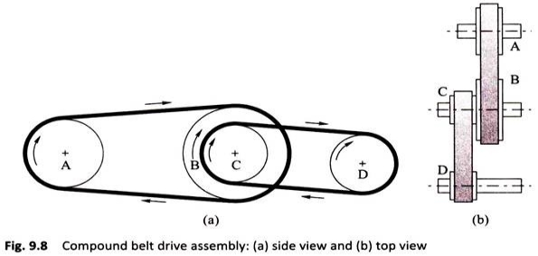
6. Compound Belt Drive System:
In compound belt drive arrangement power is transmitted from one shaft to another through a number of pulleys.
V-BELTS DRIVE-
The V-belts or “V” types of belt drives are widely used in high power transmission. V-belts are trapezoidal in section as shown in the figure. They are moulded as endless loops from rubber reinforced with fibrous material. They run in the v-grooves made in the pulleys.
The wedging action of the belts in the V-grooves enables them to transmit higher torques. The power transmitted by a v-belt drive and be increased by operating with several belts placed side.
This form of drive is used extensively in all classes of machinery transmitting power from 0.5 kW up to 150kW.
Advantages of Belt-drive:
A belt-drive has following advantages:
- It can easily install and easily remove.
- The price of the belt drive is low.
- Simple in construction.
- The maintenance cost is low.
- No additional lubricant is required.
- It can transfer power vertical, horizontal and inclined too.
- Power consumption is low.
Disadvantages of Belt-drive:
- Power loss due to slip and creep.
- Not used for a very short distance.
- Speed is limited to some extent.
- It is quieter.
- Longer life is not possible.
- Chances of breaking are more.
- The operation temperature is limited between -35 to 85 degrees Celsius. If it exceeds temperature then it causes wear.
- Angular velocity ratio is not necessarily constant or equal to the ratio of pulley’s diameter because of slipping.
Applications of Belt-drive: Belt-drives are used in various places like:
- A belt drive is used to transfer power.
- The belt drive is used in the Mill industry.
- The belt drive is used in Conveyor.
We have seen in belts that slipping is occurs. In order to avoid slipping steel chains are used. The chain are made up of rigid links which are hinged together in order to provide the necessary flexibility for wrapping around the driving and driven wheel. The tooth wheels are known as sprocket wheels or simple sprockets.
A chain drive is a mechanically operating system where we used different types of chains to transmit the power or for movement of something.
Generally, a chain drive is used where the distance between the power produced and where it to be transferred is less, however, this is not applicable for all. In some cases, we can use a chain drive for longer distances power transfer.In belt or rope drive we see there is some percent of slip occurs, but in the chain, there will be no slip. But this does not mean that 100% power is transmitted from one to another device due to friction loss some amount of power loss we can generally see.
![Chain Drives: 5 Types of Chains [Advantages/Disadvantages]](https://glossaread-contain.s3.ap-south-1.amazonaws.com/epub/1642920920_782159.jpeg)
In chain drive, the speed ratio remains constant which is a major advantage of chain drive and here there is no slippage and in case of belt drive, there is slippage so speed ratio changes as per slippage. A chain is made by a number of links and those are connected by the help of a pin.
Chains are run over a wheel named sprocket which has several amounts of teeth around the circumference of that to grip the chain, however, not all the chains need that sprocket to run over
Types of Chains:
In the field of Mechanical Engineering chains drive can be classified into three broad categories and those are:
- Hoisting Chains
- Conveyor Chains
- Power transmission Chains.
1) HOISTING CHAINS:
A hoist is a mechanical device which is used to lift a load or lowering a load, it can be used for shifting of some heavy product from one place to another place in a workstation. The chains used in this type of devices is named hoist chain, these chains are quite strong to handle heavyweight.
Hoist chains can be classified into two categories:
- Oval-Link Chains.
- Stud-Link Chains.
i) Oval-Link Chains:
It is one of the common types of chain used in hoist; it consists of many oval links attached to each other. These types of chains are also called Coil Chains. Links of this type of chain is oval. However, there are square link types of chains that are also available, but the kinking is occurred easily due to high loading.
Ii) Stud-Link Chains:
The stud-link chains used to minimize the deformation and link or tangle easily. In this type of chain, a round bar or stud is used to fit inside the oval-link chains to provide more strength to the chain. The stud-link chains used to minimize the deformation and link or tangle easily. In this type of chain, a round bar or stud is used to fit inside the oval-link chains to provide more strength to the chain. It is used in Ship to up and down the anchor of the ships, and some crane hoist where we need to lift a very high amount of load.
2) CONVEYOR CHAINS:
As the name suggests conveyor chains that means these types of chains are mostly used in the conveyor. The conveyor is a mechanical device system that is used to move the materials from one place to another. This type of chain is well shaped that it can easily run over the sprocket.
Generally, this type of chain is made of malleable cast iron and used in Low-Speed Machinery approx. 2 m/s.
The one major disadvantage of this type of chain is the motion of the chain is not smooth, there are chances of wear and tear out.
Conveyor Chains are categorized into following types:
- Detachable or Hook Joint types Conveyor chain.
- Closed-end pintle type conveyor chain.
- Detachable or Hook Joint types Conveyor chain: Detachable or Hook Joint types Conveyor chains are used in a conveyor where the length between power transmissions is short.
- Closed-end pintle type conveyor chain: This type of chain is consists of a barrel and link and made in a single casting, and then the chain is heat-treated to provide higher strength.
3) POWER TRANSMISSION CHAINS:
You can easily find out by name of the chain that it is used to transmit the power. This type of chain is made of steel and sometimes it heats treated to minimize wear and tear. This type of chain has greater accuracy and can easily run over the sprocket.
Power Transmission Chains are categorized into three types:
- Block Chain
- Roller Chain
- Silent Chain or Inverted tooth Chain
- Block Chain: This type of chain is used in low-speed areas and will produce noise due to the sudden contact between sprocket and chain, however, this is used in some low-speed conveyor machines.
Ii. Roller Chain: This type of chain is constructed by:
- A bush
- Inner Link
- A pin
- Outer Plate
- Inner plate
- Rollers
In this type of chain, a bush along with the roller is fitted inside both the plates then a pin is passed through both the end of the roller to fasten it. The rollers are free to rotate inside the bush so that when it contacts between the sprocket the wear tear would be minimized.
Generally, it is made of steel. It is soundless and wears less as compared to the blockchains and used in any circumstances and this type chains gave much service area if proper lubrication is maintained. It is used in high-speed power transmission devices, like a motorcycle.
Iii) Silent Chain or Inverted Tooth Chain:
The operation of this type of chain is quite silent and can be used in high-speed power transmissions areas. This type of chain does not have any roller, it is accurately shaped that it can easily sit over the sprocket. However, lubrication is an important factor for this type of chain otherwise it will wear and tear out.
Advantages of Chain drive:
A chain drive has several advantages like:
Low maintenance.
Greater efficiency up to 97 percent.
Slipping is negligible
Chain drive can operate in wet conditions too.
It can withstand abrasive conditions.
The chain drive is easy to install.
Initial tension is not required in chain drive.
Even in fire hazards it does not faces any bad problem.
Multiple hafts can be driven from a single chain drive.
Chain drive requires less space and it is more compact than belt drive.
It produces less stress on the shaft because the sprockets are lighter than pulleys.
Transmit higher power compared to belt drive.
Chain drive, the speed ratio is good as compared to belt drive.
It can be used in reversing drives.
It can be operated at a high temperature Like a belt which cants not operate at high temperatures.
Chain drive can be used up to 3 m in distances between small and large centres.
Disadvantages of Chain drive:
These are some disadvantages of using Chain:
The major disadvantages are here it requires more and frequent lubrication otherwise rust problem comes.
It cannot be used where there is a requirement of slips.
We can’t keep chain drive-in open. It needs housing or covering.
It cannot be used for précised motion requirements.
It is noisy and therefore there is a problem of vibration too.
The installation or initial cost is more.
The velocity fluctuation is more.
Application of chain drive:
There are plenty of applications of a chain drive some of them are:
Chain drive used for transmission of power.
It is used for lifting loads and also used to carry material.
This is also used in woodworking machinery.
A gear is a kind of machine element in which teeth are cut around cylindrical or cone shaped surfaces with equal spacing. By meshing a pair of these elements, they are used to transmit rotations and forces from the driving shaft to the driven shaft. Gears can be classified by shape as involute, cycloidal and trochoidal gears. Also, they can be classified by shaft positions as parallel shaft gears, intersecting shaft gears, and non-parallel and non-intersecting shaft gears.
Types of Gears
Following are the different types of gears:
- Parallel gears
- Spur Gears
- Helical Gears
- Double Helical or Herringbone Gears.
- Intersecting gears
- Spiral gears
- Bevel Gears
- Non-intersecting and Non-Parallel gears.
- Worm Gears
- Rack and Pinion gears
1) Parallel gears - As indicated by the name, parallel configurations involve gears connected to rotating shafts on parallel axes within the same plane. The rotation of the driving shaft (and the driving gear) is in the opposite direction to that of the driven shaft (and driven gear), and the efficiency of power and motion transmission is typically high.
a) Spur gear:
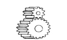
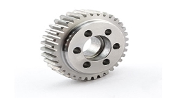
Spur gears transmit power through shafts that are parallel. The teeth of the spur gears are parallel to the shaft axis. This causes the gears to produce radial reaction loads on the shaft, but not axial loads. Spur gears tend to be noisier than helical gears because they operate with a single line of contact between teeth. While the teeth are rolling through mesh, they roll off of contact with one tooth and accelerate to contact with the next tooth. This is different than helical gears, which have more than one tooth in contact and transmit torque more smoothly.
b) Helical Gear:
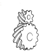
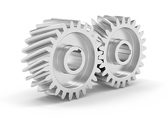
Helical gears have teeth that are oriented at an angle to the shaft, unlike spur gears which are parallel. This causes more than one tooth to be in contact during operation and helical gears are capable of carrying more load than spur gears. Due to the load sharing between teeth, this arrangement also allows helical gears to operate smoother and quieter than spur gears. Helical gears produce a thrust load during operation which needs to be considered when they are used. Most enclosed gear drives use helical gears.
c) Double Helical Gear:
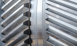
Double helical gears are a variation of helical gears in which two helical faces are placed next to each other with a gap separating them. Each face has identical, but opposite, helix angles. Employing a double helical set of gears eliminates thrust loads and offers the possibility of even greater tooth overlap and smoother operation. Like the helical gear, double helical gears are commonly used in enclosed gear drives.
d) Herringbone Gear
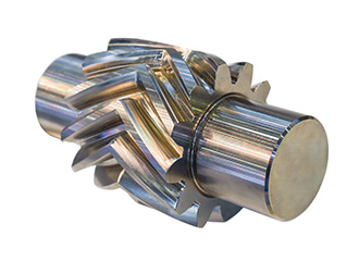
Herringbone gears are very similar to the double helical gear, but they do not have a gap separating the two helical faces. Herringbone gears are typically smaller than the comparable double helical, and are ideally suited for high shock and vibration applications. Herringbone gearing is not used very often due to their manufacturing difficulties and high cost.
2) Intersecting gears
Bevel gear: Bevel gears are most commonly used to transmit power between shafts that intersect at a 90 degree angle. They are used in applications where a right angle gear drive is required. Bevel gears are generally more costly and are not able to transmit as much torque, per size, as a parallel shaft arrangement.
Bevel gear transmits power between two intersecting shafts at any angle or non-intersecting shaft. They are classified as straight and spiral tooth bevel and hypoid gears. These are gears cut from conical blanks and connect intersecting shaft axes.
The connecting shaft is generally at 90°and sometimes one shaft drives a bevel gear which is mounted on a through the shaft resulting in two output shafts. The point of intersection of the shaft is called the apex and the teeth if the two gears converge at the apex.
There are several types of bevel gears available differentiated mainly by their tooth design. Some of the more common types of bevel gears include straight, spiral, and Zero bevel gears.
a) Straight Bevel Gears
The most commonly used of the bevel gear tooth designs due to its simplicity and, consequently, its ease of manufacturing, straight bevel teeth are designed such that when properly matched straight bevel gears come into contact with one another, their teeth engage together all at once rather than gradually. As is the issue with spur gears, the engagement of straight bevel gear teeth results in high impact, increasing the level of noise produced and amount of stress experienced by the gear teeth, as well as reducing their durability and lifespan.
b) Spiral Bevel Gears
In spiral bevel gears, the teeth are angled and curved to provide for more gradual tooth engagement and more tooth-to-tooth contact than with a straight bevel gear. This design greatly reduces the vibration and noise produced, especially at high angular velocities (>1,000 rpm). Like helical gears, spiral bevel gears are available with right-hand or left-hand angled teeth. As is also the case with helical gears, these gears are more complex and difficult to manufacture (and, consequently, more expensive), but offer greater tooth strength, smoother operation, and lower levels of noise during operation than straight bevel gears.
Additional Bevel Gear Designs
Other than the types mentioned above, there are several other designs of bevel gears available including miter, crown, and hypoid gears.
c) Miter: Miter gears are bevel gears which, when paired, have a gear ratio of 1:1. This gear ratio is a result of pairing two miter gears with the same number of teeth. This type of bevel gear is used in applications which require a change only to the axis of rotation with speed remaining constant. When two bevel gear has their axes at right angles and is equal sizes, they are called mitre gears.
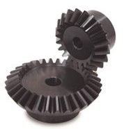
d) Crown: Crown gears, also referred to as face gears, are cylindrical (rather than conical) bevel gears with teeth cut or inserted perpendicular to the gear face. Crown gears can be paired either with other bevel gears or, depending on the tooth design, spur gears.
e) Hypoid: Originally developed for the automobile industry, hypoid gears, unlike the previously mentioned types, are a type of spiral bevel gear used for non-parallel, non-intersecting configurations. This design allows for components to be placed lower, allowing for more space in the sections above. Employing curved and angled teeth similar to those used in spiral bevel gears, hypoid gears are even more complex and, consequently, more difficult (and costly) to manufacture.
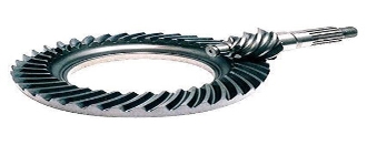
Hypoid gears look very much like a spiral bevel gear but they operate on shafts which do not intersect, which is the case with a spiral bevel gear. In the hypoid arrangement because the pinion is set on a different plane than the gear, the shafts are supported by the bearings on either end of the shaft.
3) Non-intersecting and Non-Parallel gears.
a) Worm Gears:
Worm gear pairs are comprised of a worm wheel typically a cylindrical gear paired with a worm i.e., a screw-shaped gear. These gears are used to transmit motion and power between non-parallel, non-intersecting shafts. They offer large gear ratios and capabilities for substantial speed reduction while maintaining quiet and smooth operation.
Worm gears transmit power through right angles on non-intersecting shafts. Worm gears produce thrust load and are good for high shock load applications but offer very low efficiency in comparison to the other gears. Due to this low efficiency, they are often used in lower horsepower applications.
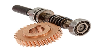
One distinction of worm gear pairs is that the worm can turn the worm wheel, but, depending on the angle of the worm, the worm wheel may not be able to turn the worm. This characteristic is employed in equipment requiring self-locking mechanisms. Some of the disadvantages of worm gears are the low transmission efficiency and the amount of friction generated between the worm wheel and worm gear which necessitates continuous lubrication.
4) Rack and Pinion Gears
A rack and pinion is a pair of gears which convert rotational motion into linear motion and vice versa. A circular gear called “the pinion” engages teeth on a linear “gear” bar called “the rack”.
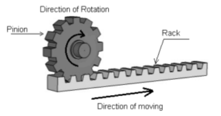
Rotational motion applied to the pinion will cause the rack to move to the side, up to the limit of its travel. The diameter of the gear determines the speed that the rack moves as the pinion turns.
A rack and pinion are commonly found in the steering mechanism of cars or other wheeled, steered vehicles. In a rack railway, the rotation of a pinion mounted on a locomotive or a railcar engages a rack between the rails and pulls a train along a steep slope, machine tools such as lathe machine, drilling machine, planning machine.
Rack and pinion gears are a pair of gears comprised of a gear rack and a cylindrical gear referred to as the pinion. The gear rack can be considered as a gear of infinite radius (i.e., a flat bar) and is constructed with straight teeth cut or inserted on the bar’s surface. Depending on the type of pinion gear with which it is mated, the gear rack’s teeth are either parallel (when mated with spur gears) or angled (when mated with helical gears). For either of these rack designs, rotational motion can be converted into linear motion or linear motion can be converted into rotational motion.
Some of the advantages of a rack and pinion gear pair are the simplicity of the design (and the low cost of manufacturing) and high load carrying capacities. Despite the advantages of this design, gears which employ this approach are also limited by it. For example, transmission cannot continue infinitely in one direction as motion is limited by the designated length of the gear rack. Additionally, rack and pinion gears tend to have a greater amount of backlash (i.e., additional space between mated gear teeth) and, consequently, the teeth experience a significant amount of friction and stress.
Some of the common applications of rack and pinion gear pairs include the steering system of automobiles, transfer systems, and weighing scales.
Types of Gear Trains
A gear train is a mechanical system formed by mounting gears on a frame. When two or more gears mesh together to transmit power from one shaft to another such arrangement is called a gear set or a gear train.
Sometimes two or more gears are made to mesh with each other to transmit power from one shaft to another such a combination is called “gear train of the wheel”. Also, each gear is generally attached to a shaft often gears that are meshed together will be of different sizes in this case the smaller gear is referred to as the pinion and the larger one is simply referred to as the gear.
Following are the different types of gear trains:
- Simple gear train
- Compound gear trains
- Reverted gear trains
- Epicyclic gear trains
1. Simple Gear Trains
In these types of gear trains, the distance between the two wheels is great. The motion from one wheel to another is transmitted by providing one or more intermediate wheels as shown in the figure.
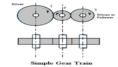
When the number of intermediate wheels is odd, the motion of driver and follower is like as shown in the figure. If the number of intermediate wheels is even the motion of the follower will be in the opposite direction of the driver as shown in the figure.
The speed ratio (or velocity ratio) of gear train is the ratio of the speed of the driver to the speed of the driven or follower and ratio of speeds of any pair of gears in mesh is the inverse of their number of teeth, therefore
Speed ratio: Speed of driver /speed of driven = NO. Of teeth on driven /No. Of teeth on driver.
Speed ratio = N1/N2 = T2 / T1
The train value may be noted that ratio of the speed of the driven or follower to the speed of the driver is known as train value of the gear train. Mathematically,
Train value: Speed of driven /speed of driver = NO. Of teeth on driver /No. Of teeth on driven.
Train value = N2 / N1 = T1 / T2
2. Compound Gear Train
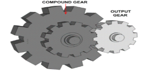
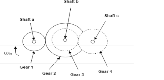
In compound gear train, each intermediate shaft has two wheels fixed to it. These wheels have the same speed. One wheel gears with the drier and the other wheel gears with the follower attached to the next shaft.
Speed ratio: Speed of first driver /speed of last driven = Product of the number of teeth on driven /product of the number of teeth on driver
Speed ratio = N1 / N6 = T2 X T4 X T6 / T1 X T3 X T5
Train value: Speed of last driver /speed of first driven = Product of the number of teeth on driver /product of the number of teeth on driven
3. Reverted Gear Trains
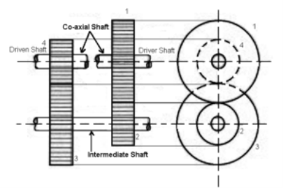
When the axes of the first and last wheels are co-axial the train is known as “reverted gear trains” as shown fig. Since the motion of the first and last wheel is alike, therefore a compound wheel is provided. Since the distance between the centres of the shaft 1 and 2 as well as 3 and 4 is the same.
Speed ratio: Speed of first driver /speed of last driven = Product of the number of teeth on driven /product of the number of teeth on drivers
Epicyclic gear train: the axes of the shaft, over which the gears are mounted, move relative to a fixed axis. A simple epicyclic or planetary gear train is shown the figure.
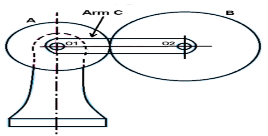
Here wheel A and arm C have a common axis at O1 about which they can rotate. The wheel B meshes with wheel A and has its axis on the arm at O2, about which the wheel B can rotate. If wheel A is fixed and the arm is rotated, the train becomes an “epicyclic gear train”.
Centrifugal pump is a hydraulic machine which converts mechanical energy into hydraulic energy by the use of centrifugal force acting on the fluid. These are the most popular and commonly used type of pumps for the transfer of fluids from low level to high level. Its is used in places like agriculture, municipal (water and wastewater plants), industrial, power generation plants, petroleum, mining, chemical, pharmaceutical and many others.
Pumps are the mechanical devices that convert mechanical energy into hydraulic energy. They are generally used to raise the water or other fluids from lower elevation to higher elevation. So pumps are generally classified into centrifugal pump and positive displacement pump. Centrifugal pumps are non- positive displacement pumps. They work on the principle of centrifugal action.
The Main parts of Centrifugal Pump are:
1. Impeller
It is a wheel or rotor which is provided with a series of backward curved blades or vanes. It is mounded on the shaft which is coupled to an external source of energy which imparts the liquid energy to the impeller there by making it to rotate.
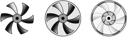
Fig 2: Open, Semi Enclosed and Enclosed Impeller.
Impellers are divided into following types,:
a) Based on direction of flow:
1) Axial-flow: – the fluid maintains significant axial-flow direction components from the inlet to outlet of the rotor.
2) Radial-flow: – the flow across the blades involves a substantial radial-flow component at the rotor inlet, outlet and both.
3) Mixed-flow: – there may be significant axial and radial flow velocity components for the flow through the rotor row.
b) Based on suction type:
1) Single suction: – liquid inlet on one side.
2) Double suction: – liquid inlet to the impeller symmetrically from both sides.
c) Based on mechanical construction:
1) Closed: – shrouds or sidewall is enclosing the vanes.
2) Open: – no shrouds or wall to enclose the vanes.
3) Semi–open or vortex type.
2. Casing
It is a pipe which is connected at the upper end to the inlet of the pump to the centre of impeller which is commonly known as eye. The double end reaction pump consists of two suction pipe connected to the eye from both sides. The lower end dips into liquid in to lift. The lower end is fitted in to foot valve and strainer.
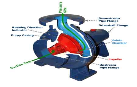
Fig 3: Main Components of Centrifugal Pump.
Commonly three types of casing are used in centrifugal pump are –
1) Volute casing: – It is spiral type of casing in which area of flow increase gradually. The increase in area of flow decreases the velocity of flow and increases the pressure of water.
2) Vortex casing: – if a circular chamber is introduced between casing and the impeller, the casing is known as vortex casing.
3) Casing with guide blades: – the impeller is surrounded by a series of guide blades mounted on a ring know as diffuser.
3. Delivery Pipe
It is a pipe which is connected at its lower end to the out let of the pump and it delivers the liquid to the required height. Near the outlet of the pump on the delivery pipe, a valve is provided which controls the flow from the pump into delivery pipe.
4. Suction Pipe with Foot Valve and Strainer
Suction pipe is connected with the inlet of the impeller and the other end is dipped into the sump of water. At the water end, it consists of foot value and strainer. The foot valve is a one way valve that opens in the upward direction. The strainer is used to filter the unwanted particle present in the water to prevent the centrifugal pump from blockage.
Working of Centrifugal Pump:
Water is drawn into the pump from the source of supply through a short length of pipe (suction pipe). Impeller rotates; it spins the liquid sitting in the cavities between the vanes outwards and provides centrifugal acceleration with the kinetic energy.
This kinetic energy of a liquid coming out an impeller is harnessed by creating a resistance to flow. The first resistance is created by the pump volute (casing) that catches the liquid and shows it down.
In the discharge nozzle, the liquid further decelerates and its velocity is converted to pressure according to BERNOULLI’S PRINCIPAL.
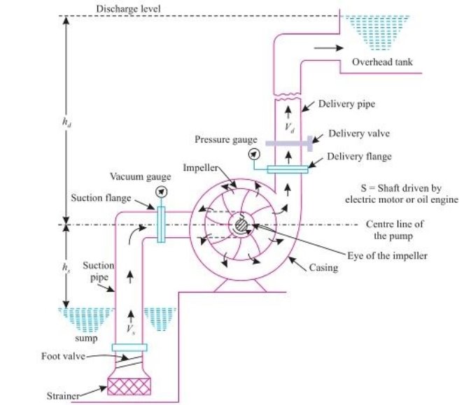
Working of a Centrifugal Pump
Let us understand in detail, how a Centrifugal pump works. Centrifugal pumps are used to induce flow or raise a liquid from a low level to a high level. These pumps work on a very simple mechanism. A centrifugal pump converts rotational energy, often from a motor, to energy in a moving fluid.
The two main parts that are responsible for the conversion of energy are the impeller and the casing. The impeller is the rotating part of the pump and the casing is the airtight passage which surrounds the impeller. In a centrifugal pump, fluid enters into the casing, falls on the impeller blades at the eye of the impeller, and is whirled tangentially and radially outward until it leaves the impeller into the diffuser part of the casing. While passing through the impeller, the fluid is gaining both velocity and pressure
Efficiency of centrifugal pump:-
The efficiency of a centrifugal pump can be defined as the ratio of the output power (water) to the input power (shaft). It can be demonstrated by using the following equation.
Ef = PW / PS
Where,
Ef is efficiency
Pw is the water power
Ps is the shaft power
Some other efficiencies are given below:
- Mechanical efficiency: – It is ratio of the impeller power to the shaft power.
- Hydraulic efficiency: – It is ratio of the manometric head to the Euler head.
- Volumetric efficiency:- It is ratio of the actual to the theoretical discharge.
- Overall efficiency: – It is ratio of the water power to the shaft power.
Applications of Centrifugal Pumps:
The fact that centrifugal pumps are the most popular choice for fluid movement makes them a strong contender for many applications.they are used across numerous industries. Supplying water, boosting pressure, pumping water for domestic requirements, assisting fire protection systems, hot water circulation, sewage drainage and regulating boiler water are among the most common applications. Outlined below are some of the major sectors that make use of these pumps:
- Oil & Energy - pumping crude oil, slurry, mud; used by refineries, power generation plants
- Industrial & Fire Protection Industry - Heating and ventilation, boiler feed applications, air conditioning, pressure boosting, fire protection sprinkler systems.
- Waste Management, Agriculture & Manufacturing - Wastewater processing plants, municipal industry, drainage, gas processing, irrigation, and flood protection
- Pharmaceutical, Chemical & Food Industries - paints, hydrocarbons, petrochemical, cellulose, sugar refining, food and beverage production
- Various industries (Manufacturing, Industrial, Chemicals, Pharmaceutical, Food Production, Aerospace etc.) - for the purposes of cryogenics and refrigerants.
Advantages of Centrifugal Pumps
The centrifugal pumps advantages include the following.
a) These pumps do not include drive seals that reduce leakage risk.
b) These pumps are used to pump out harmful and risky fluids.
c) These pumps have magnetic coupling that can be damaged simply in overload situations as well as protects the pump from external forces.
d) The motor and pump are separated from each other so heat transfer is impossible from the motor to pump.
e) These pumps generate low friction.
Disadvantages of Centrifugal Pumps
The centrifugal pumps disadvantages include the following.
a) The energy loss can be occurred due to the coupling that generates some magnetic resistance.
b) Once the intense load occurs, possibilities are there for the coupling fall.
c) If fluids with ferrous particles are pumped out, then rust occurs & over the time pump stops working.
d) When the flow of liquid is less through the pump, then the overheating can occur
A reciprocating compressor is a positive-displacement machine that uses a piston to compress a gas and deliver it at high pressure.
This type of compressor uses piston-cylinder arrangement to compress the air. Whenever something moves back and forth it is considered as moving in reciprocating motion. Similarly in this type piston moves back and forth inside the cylinder and compress the air. There are two sets of valves that take care of air intake and exhaust.
The compressor takes inside successive amount of volume of air from intake valve and confined it in closed surface at that time piston moves downward with the closure of intake valve. Then there is compression of air by reducing its volume .Now the piston moves upward and compress the air and then displace the compressed air through exhaust valve. And then again intake take place and cycle repeat itself
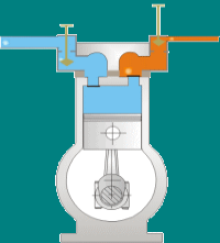
This type of compressor also called positive displacement machines. They are available in both as lubricated and oil-free.
The reciprocating compressor is single acting when the compressing is accomplished using only one side of piston and double acting when both the sides of piston used.
Major components of reciprocating compressor:
Reciprocating compressors are available in a variety of designs and arrangements. Major components in a typical reciprocating compressor are
- Frame
- Cylinders
- Distance Piece
- Piston
- Piston rings
- Cross Head
- Crankshaft
- Connecting Rod
- Valve
- Bearings
Some important parts are explained below:
Frame
The frame is a heavy, rugged housing containing all the rotating parts and on which the cylinder and crosshead guide is mounted. Compressor manufacturers rate frames for a maximum continuous horsepower and frame load .
Separable compressors are usually arranged in a balanced-opposed configuration characterized by an adjacent pair of crank throws that are 180 degrees out of phase and separated by only a crank web. The cranks are arranged so that the motion of each piston is balanced by the motion of an opposing piston.
Integral compressors typically have compressor and engine-power cylinders mounted on the same frame and are driven by the same crankshaft. Cylinders in integral compressors are usually arranged on only one side of the frame (i.e., not balanced-opposed).
Cylinder
The cylinder is a pressure vessel that contains the gas in the compression cycle. Single-acting cylinders compress gas in only one direction of piston travel. They can be either head end or crank end. Double-acting cylinders compress gas in both directions of piston travel .Most reciprocating compressors use double-acting cylinders.
Distance piece
The distance piece provides separation between the compressor cylinder and the compressor frame
Crankshaft
The crankshaft rotates around the frame axis and drives the connecting rod, piston rod, and piston .
Connecting rod connects the crankshaft to the crosshead pin
Crosshead converts the rotating motion of the connecting rod to a linear, oscillating motion that drives the piston
Piston rod connects the crosshead to the piston.
Piston and piston ring
The piston is located at the end of the piston rod and acts as the movable barrier in the compressor cylinder. Selection of material is based on strength, weight, and compatibility with the gas being compressed. The piston is usually made of a lightweight material such as aluminium or from cast iron or steel with a hollow centre for weight reduction. Thermoplastic wear (or rider) bands often are fitted to pistons to increase ring life and reduce the risk of piston-to-cylinder contact. Cast iron usually provides a satisfactorily low friction characteristic, eliminating the need for separate wear bands.
Wear bands distribute the weight of the piston along the bottom of the cylinder or liner wall. Piston rings minimize the leakage of gas between the piston and the cylinder or liner bore. Piston rings are made of a softer material than the cylinder or liner wall and are replaced at regular maintenance intervals. As the piston passes the lubricator feed hole in the cylinder wall, the piston ring gathers oil and distributes it over the length of the stroke.
Bearings
Bearings located throughout the compressor frame assure proper radial and axial positioning of compressor components. Main bearings are fitted in the frame to properly position the crankshaft. Crank pin bearings are located between the crankshaft and each connecting rod. Wrist pin bearings are located between each connecting rod and crosshead pin. Crosshead bearings are located at the top and bottom of each crosshead.
Most of the bearings in reciprocating compressors are hydrodynamic lubricated bearings. Pressurized oil is supplied to each bearing through oil supply grooves on the bearing surface. The grooves are sized to ensure adequate oil flow to prevent overheating.
Compressor valves
The essential function of compressor valves is to permit gas flow in the desired direction and to block all flow in the opposite (undesired) direction. Each operating end of a compressor cylinder must have two sets of valves. The set of inlet (suction) valves admits gas into the cylinder. The set of discharge valves is used to evacuate compressed gas from the cylinder. The compressor manufacturer normally specifies valve type and size.
Working of reciprocating compressor:
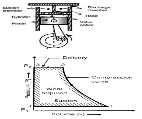
In single stage reciprocating air compressor, the entire compression is carried out in a single cylinder. The opening & closing of a simple check valve (plate or spring valve) depends upon the difference in pressure, if mechanically operated valves are used for suction & discharge then their functioning is controlled by cams. The weight of air in the cylinder will be zero when the piston is at top dead centre. At this position, you have to neglect clearance volume.
When piston starts moving downwards, the pressure inside the cylinder falls below atmospheric pressure& suction valve/inlet valve opens. The air is drawn into the cylinder through a suction filter element. This operation is known as suction stroke.
When the piston moves upwards, compresses the air in cylinder & inlet valve closes when the pressure reaches atmospheric pressure. Further compression follows as the piston moves towards the top of its stroke until when the pressure in the cylinder exceeds that in the receiver. This is compression stroke of a compressor. At the end of this stroke discharge/delivery valve opens & air is delivered to a receiver.
Advantages and disadvantages of reciprocating compressor
Advantages:
1. High thermal efficiency and low power consumption per unit
2. Convenient processing, low material requirements and low cost
3. Simple device system
4. Early design and production, mature manufacturing technology
5. Wide range of application
Disadvantages:
1. There are many moving parts, complex structure, heavy maintenance work and high maintenance cost
2. Speed Limited
3. The wear of piston ring, the wear of cylinder and the transmission mode of belt make the efficiency drop rapidly
4. Loud noise
5. The backward control system does not meet the needs of chain control and unattended, so although the price of piston machine is very low, it is often not accepted by users.
Applications:
The reciprocating compressor generally seen where there is requirement of high pressure and low flow(or discontinuous flow up to 30 bars).Mostly where the air is used for hand-tools, cleaning dust, small paint jobs, commercial uses, for examples-
1. In spray painting shop.
2. In workshop for cleaning machines.
3. For operation of pneumatic tool like rock drill, vibrator etc.
4. In automobile service station to clean vehicle.
5. To drive air motors in coal mines.
6. Food and beverage industry
Pelton Turbine is a Tangential flow impulse turbine in which the pressure energy of water is converted into kinetic energy to form high speed water jet and this jet strikes the wheel tangentially to make it rotate. It is also called as Pelton Wheel.
- The turbine capable of working under the high potential head of water is the Pelton Wheel Turbine which works on the head greater than 300 m.
- The runner consists of a circular disc with a suitable number of double semi-ellipsoidal cups known as buckets which are evenly spaced around its Periphery.
- One or more nozzles are mounted so that, each directs a jet along the tangent to the circle through the centres of the buckets called the Pitch Circle.
- A casing is provided only to prevent the splashing of water and for discharging the water to the tailrace.
Parts and Their Functions of Pelton Turbine
Different parts and their functions of Pelton turbine are as follows.
- Nozzle and Flow Regulating Arrangement
- Runner and Buckets
- Casing
- Braking Jet
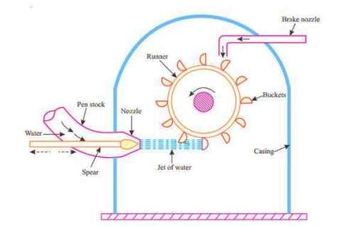
Fig 1: Parts of Pelton Turbine
1. Nozzle and Flow Regulating Arrangement
The water from source is transferred through penstock to which end a nozzle is provided. Using this nozzle the high speed water jet can be formed. To control the water jet from nozzle, a movable needle spear is arranged inside the nozzle.
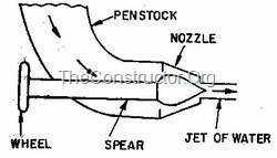
The spear will move backward and forward in axial direction. When it is moved forward the flow will reduce or stopped and when it is moved backward the flow will increase.
2. Runner and Buckets
A Pelton turbine consists of a runner, which is a circular disc on the periphery of which a number of buckets are mounted with equal spacing between them. The buckets mounted are either double hemispherical or double ellipsoidal shaped.
.
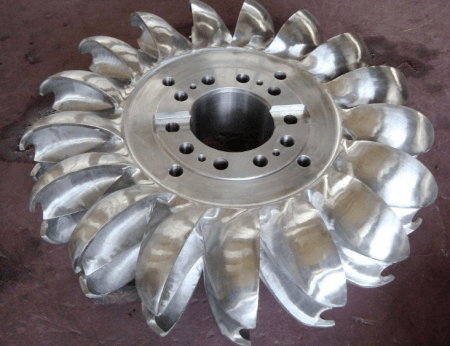
Runner and Buckets of Pelton Wheel
A dividing wall called splitter is provided for each bucket which separates the bucket into two equal parts. The buckets are generally made of cast iron or stainless steel or bronze depending upon the head of inlet of Pelton turbine
3.Casing
The whole arrangement of runner and buckets, inlet and braking jets are covered by the Casing. Casing of Pelton turbine does not perform any hydraulic actions but prevents the splashing of water while working and also helps the water to discharge to the tail race.
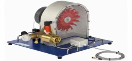
Pelton Turbine Model With Casing
4.Braking Jet
Braking jet is used to stop the running wheel when it is not working. This situation arises when the nozzle inlet is closed with the help of spear then the water jet is stopped on the buckets. But Due to inertia, the runner will not stop revolving even after complete closure of inlet nozzle.
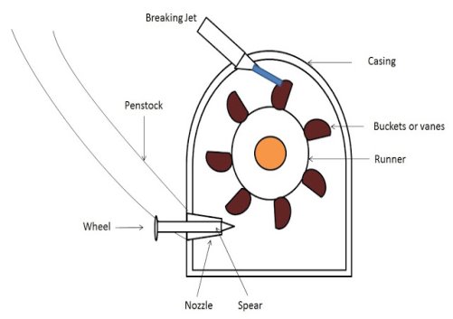
To stop this, a brake nozzle is provided as shown in figure . The brake nozzle directs the jet of water on the back of buckets to stop the wheel. The jet directed by brake nozzle is called braking jet.
Working principle of pelton wheel:
Let’s understand by the figure or layout of the hydropower plant, The water is stored at the high head. From there it comes through the penstock and reaches the nozzle of the Pelton turbine. The nozzle increases the kinetic energy of the water and directs the water in the form of the jet.
Now, the jet of water from the nozzle strikes the buckets (vanes) of the runner. So that the runner rotates at very high speed and the quantity of water striking the vanes or buckets is controlled by the spear present inside the nozzle and then the main important process is the generator is attached to the shaft of the runner which converts the mechanical energy (rotational energy) of the runner into an electrical energy.
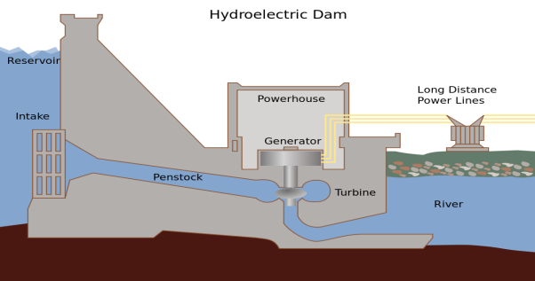
Water flows from the nozzle with high kinetic energy along the tangent to the path of the runner and when the jet of water comes in contact with the bucket, it exerts a force on the bucket called as Impulse force.
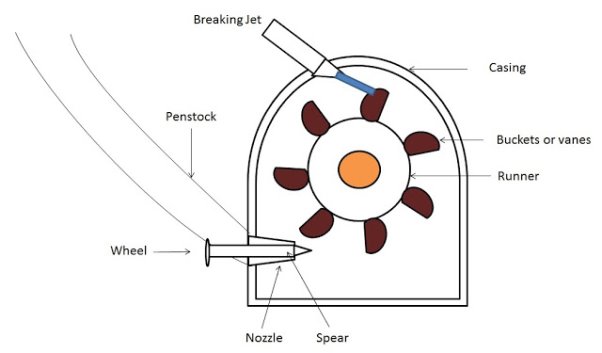
In order to control the quantity of water striking the runner, the nozzle fitted at the end of penstock is provided with a spear or needle fixed to the end of a rod.
In this process, the momentum of the water is transferred to the turbine. The impulse force produced due to this momentum of water causes the turbine to rotate.
The double Semi ellipsoidal buckets split the water jet into two halves which helps in balancing the wheel (runner). This ensures a smooth transfer of the fluid jet to the turbine wheel.
For maximum power and efficiency, the turbine is designed such that, the water Jet velocity is twice the velocity of the bucket.
Advantages of Pelton Wheel:
These are some advantages of Pelton Wheel Turbine:
- The Pelton turbine is the most efficient of hydro turbines.
- It operates with a very flat efficiency curve
- Each bucket splits the water jet in half, thus balancing the side-load forces or thrust on the wheel and thus the bearings.
- It operates on the high head and low discharge.
- It has a tangential flow which means that it can have either axial flow or radial flow.
- Pelton wheel turbine is very easy to assemble.
- There is no cavitation because water jet strikes only a specific portion of the runner.
- It has fewer parts as compared to Francis’s turbine which has both fixed vanes and guided vanes.
- The overall efficiency of the Pelton turbine is high.
- Pelton wheel turbines, both first law and the second law of motion are applied.
- The main advantages are that In this turbine, the whole process of water jet striking and leaving for the runner takes place at atmospheric pressure.
Disadvantages of Pelton Wheel:
And these are some disadvantages of Pelton Wheel Turbine:
- The efficiency decrease very quickly with time.
- The Turbine size runner, generator and powerhouse required is large.
- The variation in the operating head is difficult to control because of high heads.
Application:
Pelton turbine is used in the hydroelectric power plant where the water available at high head i.e. 150 m to 2000 m or even more. In hydroelectric power plant, it is used to drive the generator attached to it and the generator generates the mechanical energy of the turbine into electrical energy.
The Efficiency of the Impulse or Pelton wheel Turbine:
The term “efficiency” is defined as the ratio of work done to the energy supplied.
a) Hydraulic Efficiency:
It is the ratio of power generated by the runner of the turbine to the water-energy supplied to the bucket of the runner.

The expression is also written as:

Here H is a Net head developed by the water at the inlet, and it can find out by this equation:

b) Mechanical Efficiency:
It is defined as the power available at the shaft to the power produced by the runner.

c) Volumetric Efficiency:
It is a ratio of the actual quantity of water on the runner blades per second to the net quantity of water supplied by the jet to the turbine per second is known as volumetric efficiency.

Where Q= Water that actually striking on the runner & Delta Q= Amount of water discharged after striking.
d) Overall Efficiency:
It is defined as a ratio of the power available at the shaft to the net power available at the base of the nozzle.

e) Mathematical Formula of Pelton Wheel:
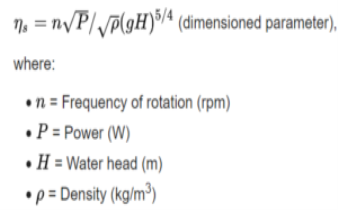
The formula of Calculating Specific Speed of a Pelton Wheel (Where ns=Specific Speed)
f) Calculation of Torque on the Runner:
T = F(D/2) = p.Q.D (Vi-u)
Where,
p = density
Q= Volume rate of flow of fluid
D= Wheel dia.
F= Force
T= torque of the runner
g) The formula of Flow Ratio:

It is the ratio of Velocity of flow at inlet to the energy head at the inlet
h) The Formula of Speed Ratio:

It is the ratio of Peripheral velocity to the energy head at the inlet
i) The formula of Peripheral velocity:

In the case of Pelton Wheel, the velocity at the inlet (U1) is equal to the velocity of the outlet (U2)
j) Calculation of Power:
The power P = Fu = T.w where w is the angular velocity of the wheel.
Question 1) A gear wheel has 50 teeth of module 5mm. Find the pitch circle diameter and the circular pitch.
Given:
Module, m= 5mm, T= 50
Find Pc=? , d =?
Solution: Module m = d / T
5 = d / 50
d=250 mm
Circular pitch, Pc= pi x d /T
Pc= pi x 250 / 50
Pc=15.7 mm (where pi= 3.14)
Question 2) Two gear wheels having 80 teeth and 30 teeth mesh with each other. If the smaller gear wheel runs at 480rpm, find the speed of the larger wheel.
Given:
Larger Gear wheel T1 = 80, N1=?
Smaller Gear Wheel T2= 30, N2= 480 rpm
Velocity ratio of gear drive
N2 / N1 = T1 / T2
N1 = N2 x T2 / T1
N1 = 480 x 30 / 80
= 180 rpm
Question 3) In a simple train of gears, A has 30 teeth, B has 40 teeth, C has 60 teeth and D has 40 teeth. If A makes 36 rpm, find the rpm of the gear C and D.
Given: TA= 30, TB= 40, TC= 60, TD= 40, NA=36 rpm
Find NC=? ND=?
Solution =
NC / NA = TA / TC
NC = NA x TA / TC
= 36 x 30 / 60
= 18 rpm
ND / NA = TA / TD
ND = NA x TA / TD
= 36 x 30 / 40
= 27 rpm
Question 4) A compound gear consists of 4 gears A, B, C and D and they have 20, 30, 40 and 60 teeth respectively. A is fitted on the driver shaft, and D is fitted on the driven shaft, B and C are compound gears, B meshes with A, and C meshes with D. If A rotates at 180 rpm, find the rpm of D.?
Given:
TA= 20, TB= 30, TC= 40, TD= 60, N A=180 rpm
Find ND=?
Solution:
ND / NA = TA x TC / TB x TD
ND = NA x TA x TC / TB x TD
ND = 180 x 20 x 40 / 30 x 60
ND = 80 rpm