Unit 6:
Manufacturing Processes
Content
a) Casting Process,
b) Steps involved in casting processes, and their applications,
a) Casting Process
Casting manufacturing is a process in which liquefied material, such as molten metal, is poured into the cavity of a specially designed mold and allowed to harden. After solidification, the workpiece is removed from the mold to undergo various finishing treatments or for use as a final product. Casting methods are typically used to create intricate solid and hollow shapes, and cast products are found in a wide range of applications, including automotive components, aerospace parts, etc.
Benefits of the Casting Process
Casting is but one method of metal shaping, as there are many other options, including welding, forging, stamping, and extrusion and machining. Before settling on casting, you should first understand the benefits that the process provides over these other techniques. The casting process:
- Ability to create complex geometries: Liquid metal facilitates construction of intricate designs, in either simple or complex geometries.
- Fast production cycles: Once the casting tools are in order, very little maintenance and downtime is necessary. This makes casting an option for mass production applications.
- Workability of hard metals: Casting is often one of the only viable manufacturing processes for hard metals that are not malleable enough for solid state shaping.
- Reduced assembly: Oftentimes, casting can create items in a single, complete component, eliminating the need to assemble multiple pieces.
- Minimal sizing restraints: Casting can create extremely small to extremely large parts, even up to 200 tons.
- Versatile surface textures: Casting moulds can be designed to deliver smooth, semi-smooth or rough surface textures.
Types of Casting Processes
There are several different casting methods, each of which requires slight variations in the process. The categorization of the different types of processes is based on the material used to make the moulds. Casting options include:
- Sand casting
- Plaster casting
- Shell moulding
- Wax casting
- Die casting
- Centrifugal casting
Although casting is one of the oldest known manufacturing techniques, modern advances in casting technology have led to a broad array of specialized casting methods. Hot forming processes, such as die-casting, investment casting, plaster casting, and sand casting, each provide their own unique manufacturing benefits. Comparing both the advantages and disadvantages of the common types of casting processes can help in selecting the method best suited for a given production run.
Sand Casting
Sand casting typically relies on silica-based materials, such as synthetic or naturally-bonded sand. Casting sand generally consists of finely ground, spherical grains that can be tightly packed together into a smooth molding surface. The casting is designed to reduce the potential for tearing, cracking, or other flaws by allowing a moderate degree of flexibility and shrinkage during the cooling phase of the process. The sand can also be strengthened with the addition of clay, which helps the particles bond more closely. Automotive products such as engine blocks are manufactured through sand casting.
Sand casting involves several steps, including patternmaking, molding, melting and pouring, and cleaning. The pattern is the form around which the sand is packed, usually in two parts, the cope and the drag. After the sand is compacted enough to replicate the pattern, the cope is removed and the pattern extracted. Then, any additional inserts called core boxes are installed and the cope is replaced. After the metal has been poured and solidified, the casting is removed, trimmed of the risers and gates that were used in the pouring process, and cleaned of any adhered sand and scale.
Sand casting's main advantages as a casting process include:
- Relatively inexpensive production costs, especially in low-volume runs.
- The ability to fabricate large components.
- A capacity for casting both ferrous and non-ferrous materials.
- A low cost for post-casting tooling.
Despite its benefits, sand casting yields a lower degree of accuracy than do alternate methods and it can be difficult to sand cast components with a predetermined size and weight specifications. Furthermore, this process has a tendency to yield products with a comparatively rough surface finish.
Investment Casting
Investment, or lost-wax, casting uses a disposable wax pattern for each cast part. The wax is injected directly into a mold, removed, then coated with refractory material and a binding agent, usually in several stages to build up a thick shell. Multiple patterns are assembled onto common sprues. Once the shells have hardened the patterns are inverted and heated in ovens to remove the wax. Molten metal is then poured into the remaining shells where it hardens into the shape of the wax patterns. The refractory shell is broken away to reveal the completed casting. Investment casting is often used to manufacture parts for the automotive, power generation, and aerospace industries, such as turbine blades. Some of the central advantages and disadvantages of investment casting include:
- A high degree of accuracy and precise dimensional results.
- The ability to create thin-walled parts with complex geometries.
- The capacity for casting both ferrous and non-ferrous materials.
- Relatively high-quality surface finish and detail in final components.
Although it is highly precise, investment casting is usually more expensive than other comparable casting techniques and is typically only cost-efficient when sand or plaster castings cannot be used. However, the expense can sometimes be compensated for with reduced machining and tooling costs due to investment castings’ quality surface results.
Plaster Casting
Plaster casting is similar to the sand casting process, using a mixture of gypsum, strengthening compound, and water in place of the sand. The plaster pattern is typically coated with an anti-adhesive compound to prevent it from becoming stuck against the mold, and the plaster is capable of filling in any gaps around the mold. Once the plaster material has been used to cast the part, it usually cracks or forms defects, requiring it to be replaced with fresh material. The advantages offered by plaster casting include:
- A very smooth surface finish.
- The ability to cast complex shapes with thin walls.
- The capacity for forming large parts with less expense than other processes, such as investment casting.
- A higher degree of dimensional accuracy than that of sand casting.
This process tends to be more expensive than most sand casting operations and may require frequent replacements of the plaster molding material. It is usually more effective and cost-efficient when the quality of the surface finish is an important requirement. Its application is generally limited to casting aluminium and copper-based alloys.
Die Casting (Metal Casting Process)
Die casting is a method of molding materials under high pressure and usually involves non-ferrous metals and alloys, such as zinc, tin, copper, and aluminium. The reusable mold is coated with a lubricant to help regulate the die’s temperature and to assist with component ejection. Molten metal is then injected into the die under high pressure, which remains continuous until the workpiece solidifies. This pressurized insertion is rapid, preventing any segment of the material from hardening before being cast. After the process is completed, the component is taken out of the die and any scrap material is removed. A few of the major advantages provided by die casting include:
- Close size and shape tolerances.
- High component dimensional consistency and uniform design.
- A reduced need for post-casting machining.
Despite its advantages, die casting as a metal casting process has relatively high tool costs, making it more cost-efficient in high-volume product runs. It can also be difficult to ensure the mechanical properties of a die-cast component, meaning these products usually do not function as structural parts. As the molds are typically two-piece, die casting is limited to products that can be removed from the mold without destroying the mold, as is done in other casting processes.
Centrifugal Casting
Centrifugal casting is used to produce long, cylindrical parts such as cast iron pipe by relying on the g-forces developed in a spinning mold. Molten metal introduced into the mold is flung against the interior surface of the mold, producing a casting that can be free of voids. Originally invented as the de Levied process using water-cooled molds, the method is applied to symmetrical parts such as soil pipe and large gun barrels and has the advantage of producing parts using a minimal number of risers. For asymmetric parts that cannot be spun around their own axes, a variant of centrifugal casting, called pressure casting, arranges several parts around a common sprue and spins the molds around this axis. A similar idea is applied to the casting of very large gear rings, etc. Depending on the material being cast, metal or sand molds may be used.
Permanent Mold Casting
Permanent mold casting shares similarities with die casting and centrifugal casting, notably the use of reusable molds. These can be made of steel, graphite, etc. and are generally used to cast materials such as lead, zinc, aluminium and magnesium alloys, certain bronzes, and cast iron. It is a low-pressure process with pouring usually done by hand using multiple molds on a turntable. As the molds rotate through the various stations they are successively coated, closed, filled, opened, and emptied. One such method is known as slush casting, where the mold is filled but emptied before the metal fully hardens. Molten metal is dumped from the casting to produce a hollow, cast shell. A similar idea is used in the molding of hollow chocolate products such as Easter bunnies. The use of metal molds induces faster heat transfer through the mold, allowing the shell to harden while the core remains liquid.
b) Steps involved in casting processes
There are many steps and things to consider when manufacturing products through the technique of casting and the casting process. This guide explains the process involved with casting and benefits of using this popular forming method.
In casting, a molten metal or other material fills a mold, then cools and hardens into a desired shape. However, a manufacturer must plan out post-cast steps to ensure effective results. Proper care should be taken at each step to deliver a final product that maintains proper quality and integrity.
Basic Steps in Casting Process
While each casting method creates unique challenges and process enhancements, all techniques retain the same basic steps. These steps are:
- Patternmaking
- Core making
- Molding
- Melting and pouring
- Finishing
Patternmaking
To create a casting mould, a manufacturer must first design a physical model. The process of fabricating this model is called patternmaking. Using computer-assisted design (CAD) systems, the manufacturer designs dimensions and geometry of a mould, and then packs an aggregate material, such as sand, concrete or plastic, around the pattern. Once the pattern is removed, the mould cavity in the sand can be filled.
A pattern is a replica of the exterior of the casting. Patterns are typically made of wood, metal, plastic, or plaster. Patternmaking is incredibly important for industrial part-making, where precise calculations are needed to make pieces fit and work together.
Core making – If a casting is hollow, an additional piece of sand or metal (called a core) shapes the internal form to make it hollow. Cores are typically strong yet collapsible so they can be easily removed from the finished casting.
Many part designs require the inclusion of cores in the casting mould. Cores are solid materials placed inside the mould cavity to create interior surfaces of a casting. For example, a metal pipefitting will require a cylindrical core inside the mould cavity to create the hollow construction of the components interior
Moulding – At this point, the manufacturer can create the casting mold. A material such as sand, plaster or wax is used in expendable mold casting, whereas metal and other durable materials are used in non-expendable mold casting techniques. The material fills the casting mold model and is allowed to harden, at which point the manufacturer removes it from the cavity and the casting of the component can now begin.
To visualize the metal casting process so far, imagine yourself walking on the beach toward the ocean. Look at a footprint you leave behind in the wet sand. Your foot would be the core, and the impression left in the sand is a mould of your foot. Molding is a multistep process that will form a cast around the pattern using moulding sand. In casting, a mould is contained in a frame called a flask. Green sand, or moulding sand, is packed into the flask around the pattern. This is known as metal sand casting. Once the sand is packed tight, the pattern can be removed and the cast will remain. Alternatively, a two-piece, non-destructible metal mould can be created so that the mould can be used repeatedly to cast identical parts for industrial applications.
Melting and Pouring
Metal must be properly melted prior to being placed in the mold. Typically, this is done by using what is known as a crucible. Crucibles are containers made of porcelain or another melt-resistance substance in which a manufacturer can heat a metal beyond its melting point. Once properly melted, the molten metal is poured into the casting mold to cool and harden.
Finishing
Because metal can sometimes fill in cracks in a casting mold or sprues, the pouring channel for the mold, manufacturers must often finish the metal following casting. This can be accomplished through a variety of finishing techniques, including sanding, grinding and buffing. Once proper appearance and surface texture has been achieved, further post-treatment processes such as painting or electroplating may be necessary for some applications.
Things to Consider When Casting
There are numerous factors that need to be considered to ensure proper size, shape and integrity of the final component. Some of these factors include:
- Type of material: each metal and casting material retains specific characteristics (hardness, melting point, density, etc.) that will affect the casting process.
- Cooling rate: This factor depends largely on the type of material from which you craft the mold. Proper cooling is necessary to minimize gas porosity and other negative properties that can result from a fast cooling rate.
- Shrinkage: As castings cool, they shrink. To ensure proper component size and integrity, you can utilize risers to feed additional molten metal into the cavity. An oversized mold may also be useful in some applications.
Casting applications
Castings can range in size from a few grams (for example, watch case) to several tones (marine diesel engines), shape complexity from simple (manhole cover) to intricate (6-cylinder engine block) and order size one-off (paper mill crusher) to mass production (automobile pistons).
The desired dimensional accuracy and surface finish can be achieved by the choice of process and its control. Castings enable many pieces to be combined into a single part, eliminating assembly and inventory and reducing costs by 50% or more compared to machined parts. Unlike plastics, castings can be efficiently and completely recycled.
Today, castings are used in virtually all walks of life. The following is a partial list of applications, with transport sector and heavy equipment taking up over 50% of castings produced:
- Transport: automobile, aerospace, railways and shipping
- Heavy equipment: construction, farming and mining
- Machine tools: machining, casting, plastics moulding, forging, extrusion and forming
- Plant machinery: chemical, petroleum, paper, sugar, textile, steel and thermal plants
- Defense: vehicles, artillery, munitions, storage and supporting equipment
- Electrical machines: motors, generators, pumps and compressors
- Municipal castings: pipes, joints, valves and fittings
- Household: appliances, kitchen and gardening equipment, furniture and fittings
- Art objects: sculptures, idols, furniture, lamp stands and decorative items.
Virtually any metal or alloy that can be melted can be cast. The most common ferrous metals include grey iron, ductile iron, malleable iron and steel. Alloys of iron and steel are used for high performance applications, such as temperature, wear and corrosion resistance. Table 1 lists the major metals in use today (by weight) along with their main characteristics and typical applications.
The most used metals, characteristics and applications
Metal | Use | Characteristics | Applications |
Grey | 54% | Heat resistance, damping, low cost, | Automobile cylinder block, clutch plate, |
Ductile | 20% | Strength, wear and shock resistance, | Crank shafts, cam shafts, differential |
Steel | 9% | Strength, machinability, weldability | Machine parts, gears, valves |
Material removal process is a type of manufacturing process in which the final product is obtained by removing excess metal from the stock. The best example of a machining process is generating a cylindrical surface from a metal stock with the help of a lathe.
This is one of the most expensive manufacturing process among the four basic manufacturing processes i.e. forming, casting, fabrication and material removal.
Types of material removal processes
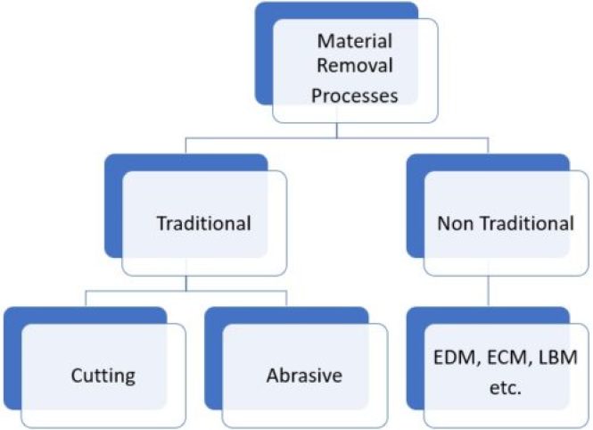
Material removal processes are mainly divided into two types traditional and non-traditional.
Traditional machining processes are the processes which are used from the ancient times till today. They are used for almost all general kind of product manufacturing. Examples of these processes are turning, drilling, lapping etc.
Non-traditional machining processes are the processes which are not in general use and are only used for very high-quality engineering works. Examples of non-traditional material removal processes are Electro Chemical Machining (ECM), Electric Discharge Machining (EDM) etc.
With the help of below diagram you can further understand the types of material removal processes in a better way.
Types of Machine Tooling
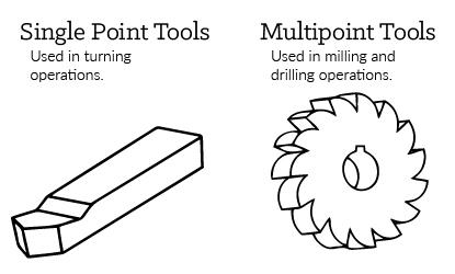
Single point tools -
- Turning Process: This type of tool rotates a workpiece while the cutting tool moves in a linear motion. This process can either be done manually or automatically
Multi-point tools -
- Drilling Process: Tool creates or refines round holes in a workpiece. This is usually done through a rotary tool with two or four helical cutting edges
- Milling Process: This type of tool creates designs by removing material from the working piece by rotating a cutting tool
Single Point v/s Multi-point Tools
The desired form of the material will determine what type of tools you’ll need for the job. The two basic types of cutting tools are single point and multi-point tools. Use single point tools for turning, boring, and planning. Use multi-point tools for milling and drilling. It is imperative to properly use and maintain the cutting tools for quality purposes. Unfortunately, proper upkeep of machinery and tooling is where it can get costly.
Tooling is available in a variety of materials. The most common are carbide and high-speed steel. You may choose to use high-speed steel (HSS) for general purpose milling. But, opt for carbide to machine tougher and harder tool steels.
Cutting Speed, Feed Rate, Depth
Cutting speed, feed rate, and depth of cut are all parameters to consider when machining. The workpiece material, tooling material, and dimensions will influence these parameters. Cutting speed refers to how fast the cutting tool cuts into the workpiece material. It’s measured in surface feet per minute. Cutting feed refers to how fast the workpiece moves across its axis toward the cutting tool. It’s measured in inches per minute.
Speeds and Feeds Calculators
Turning Speed and Feed Calculator
Drilling Speed and Feed Calculator
Milling Speed and Feed Calculator
Like artistic sculpting, the workpiece first undergoes one or more roughing cuts. Their purpose is to get as close to the finished shape and dimensions as possible. After the roughing phase, a finishing cut is applied to achieve final dimensions, tolerances, and surface finish. Finishing cuts are typically done at low feeds and depth. Applying cutting fluid during both cutting phases cools and lubricates the cutting tool.
Machine Turning
Turning involves rotation of the work piece while the cutting tool moves in a linear motion. This results in a cylindrical shape. A lathe is the machine of choice for all turning operations.
Like most machining operations, turning is either done manually or automatically. The downside to manual turning is it requires continuous supervision. Automatic turning does not. With Computer Numerical Control, or CNC, you program all the movements, speeds, and tooling changes into a computer. These instructions then get sent to the lathe for completion. CNC allows for consistency and efficiency of high production runs.
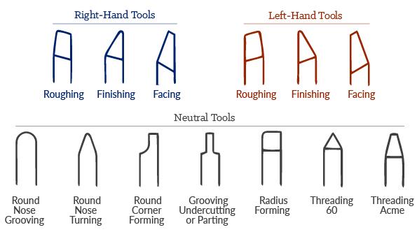
Single point cutting tools used in turning come in various shapes. They’re placed at different angles for a variety of outcomes.
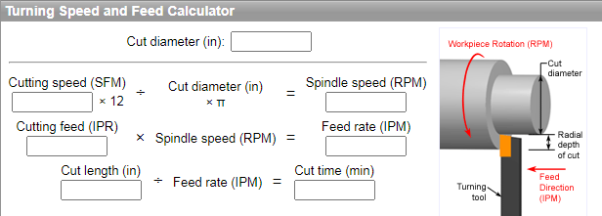
Turning Speed and Feed Calculator
Determine the spindle speed (RPM) and feed rate (IPM) for a turning operation, as well as the cut time for a given cut length. Turning operations remove material from a rotating workpiece by feeding a single-point cutting tool axially, along the side of the workpiece. Calculations use the desired cut diameter, cutting speed, and cutting feed, which should be chosen based on the specific cutting conditions, including the workpiece material and tool material. In some turning operations, the diameter of the workpiece will change so the spindle speed and cutting speed (SFM) must change as well. Typically, values are calculated for a single cut diameter and then either the spindle speed or cutting speed is held constant while the other varies.
Machine Drilling
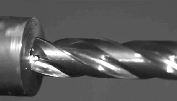
Drilling creates a round hole in a workpiece. A drill press or tapping machine is designed for drilling, but this process can also be performed using a milling machine. Chips are the bits of waste metal produced when machining a workpiece. The shape of the drill bit helps chips fall away from the workpiece, keeping the workpiece free of debris.
Placing the drill bit perpendicular to the workpiece reduces drifting or leading-off. For even more precision, a center drill operation is often added before drilling. Some drilling operations need angular drilling. Angular drilling requires special work-holding tooling. Other options include: rotation of the head on a manual machine or use of multiple axis’ on a CNC machine.
Ways to prevent drifting include:
- Casting/molding/forging a mark
- Center punching
- Spot drilling/center drilling
- Spot facing
Like with turning operations, different drill bits exist for specific drilling operations. Below are a few special drill bits along with their specific uses.
- Spotting Drills – short drills used to create shallow or pilot holes. If using a longer drill for these shallow holes it could have a tendency to drift.
- Peck Drilling – frequent retracting of the drill helps to clear chips from the workpiece and prevent drifting.
- Screw Machine Drills – these drills are short and can create straight and accurate holes without the need for prior spotting.
- Chucking Reamers – used to enlarge previously drilled holes to very precise diameters.
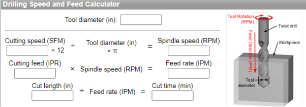
Drilling Speed and Feed Calculator
Determine the spindle speed (RPM) and feed rate (IPM) for a drilling operation, as well as the cut time for a given cut length. Drilling operations are those in which a cutting tool with sharp teeth, such as a twist drill, rotates and feeds into the workpiece axially, forming a hole with a diameter equal to that of the tool. Calculations use the desired tool diameter, cutting speed, and cutting feed, which should be chosen based on the specific cutting conditions, including the workpiece material and tool material.
Milling Process
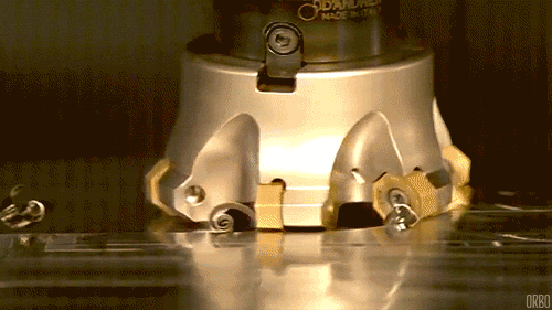
Milling operations involve using multi-point rotary cutters to remove material from a workpiece.
There are two main types of milling operations: face milling and peripheral milling. Face milling cuts flat surfaces into the workpiece and flat-bottomed cavities. The feed can be either horizontal or vertical. Peripheral milling cuts deep slots, threads, and gear teeth.
The workpiece can be fed into the cutting tool in either of two ways. Conventional milling involves feeding the workpiece against the cutter rotation. This is the recommended method for manual milling machines. Climb milling, on the other hand, feeds the workpiece in the same direction as the cutter rotation. This is the preferred method for CNC milling.
Milling is best applied as a secondary process to an already machined workpiece. It helps to define features and serves as a “finishing coat”. Use milling as a secondary process to add features such as holes, slots, pockets, and contours.
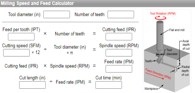
Milling Speed and Feed Calculator
Determine the spindle speed (RPM) and feed rate (IPM) for a milling operation, as well as the cut time for a given cut length. Milling operations remove material by feeding a workpiece into a rotating cutting tool with sharp teeth, such as an end mill or face mill. Calculations use the desired tool diameter, number of teeth, cutting speed, and cutting feed, which should be chosen based on the specific cutting conditions, including the workpiece material and tool material.
Joining is an important process in a number of industries, such as aerospace, automotive, oil, and gas. Many products cannot be fabricated as a single piece, so components are fabricated first and assembled later. Joining technology can be classified as a liquid-solid-state process and mechanical means. Liquid-solid-state joining includes welding, brazing, soldering, and adhesive bonding. Mechanical joining includes fasteners, bolts, nuts, and screws.
Metal joining is a process that uses heat to melt or heat metal just below the melting temperature. Joining metal by fusion is known as fusion welding. Without fusion, the process is known as solid-state welding. Fusion welding includes arc welding and laser welding, whereas solid-state welding such as friction stir welding (FSW) where process occurred below the melting temperature.
Welding, brazing and soldering are all methods for joining two or more pieces of material – primarily metals. The key difference among these processes is the temperature used to create the joint.
Welding – for the majority of processes - involves melting of the base materials to create a consolidated joint. Welding may or may not involve the use of filler metals or shielding gases.
Brazing and soldering, in essence, are the same in that they both melt the filler metal (braze or solder) only, not the base materials. The liquid filler metal wets the base materials through capillary action. When the liquid filler metal solidifies, it is bonded to the base materials, creating a joint. What differentiates soldering and brazing is the melting temperature of the filler metal; brazing is hotter.
Each process has its advantages and disadvantages, from a processing and application perspective.
Welding
There are numerous types of welding processes, including:
- Arc
- Electron Beam
- Friction
- Laser
- Resistance
Welding has been used to join most metals known to humankind, but the process is extensively used for common manufacturing materials, such as aluminium, steel and titanium. Welded components are in use all around us in everyday life, such as in aeroplanes, bridges, buildings, cars and ships.
Arc welding
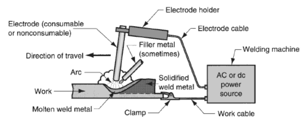
It is a fusion welding process in which the melting and joining of metals is done by the heat energy generated by the arc between the work and electrode.
An electric arc is generated when the electrode contacts the work and then quickly separated to maintain the gap. A temperature of 5500°C is generated by this arc.
This temperature is sufficient to melt most of the metals. The molten metal, consisting of base metal and filler, solidifies in the weld region. In order to have seam weld, the power source moves along the weld line.
Electrodes
• Two types of electrodes are used: consumable and non-consumable
• Consumable electrodes: Present in rod or wire form with 200 to 450 mm length and less than 10 mm diameter. This is the source of filler rod in arc welding. The electrode is consumed by the arc during the welding process and added to the weld joint as filler metal. The consumable electrodes will be changed periodically as it is consumed for each welding trials. This becomes a disadvantage for welder and reduces the production rate.
• Non-Consumable electrodes: The electrodes are not consumed during arc welding. Though this is the case, some depletion occurs because of vaporization. Filler metal must be supplied by means of a separate wire that is fed into the weld pool.
Advantages of Welding Include:
- Produces stronger joints than brazing or soldering
- Produces welded joints that are better suited for high-temperature applications
- Being able to join thin and thick sections of metal (depending on process type)
- Welding provides a permanent joint.
- Welded joint can be stronger than the parent materials if a proper filler metal is used that has strength properties better than that of parent base material and if defect less welding is done.
- • It is the economical way to join components in terms of material usage and fabrication costs. Other methods of assembly require, for example, drilling of holes and usage of rivets or bolts which will produce a heavier structure.
Disadvantages of Welding Include:
- Producing greater thermal distortion and residual stresses in the joint compared to soldering and brazing
- Requiring a post-processing heat treatment to relieve joint residual stress (depending on application and process)
- Only being able to join similar base materials (for most processes, but not all)
- Labour costs are more since manual welding is done mostly.
- Dangerous to use because of presence of high heat and pressure.
- Disassembly is not possible as welding produces strong joints.
- Some of the welding defects cannot be identified which will reduce the strength.
Soldering
Solders are melted using heat from a temperature-controlled soldering iron. The solder melts at a temperature below 450°C. A flux is used in soldering to clean the metal surfaces, allowing easier flow of the liquid filler metal over the base material.
Base materials suitable for joining by soldering include brass, copper, iron, gold and silver. Filler metals used in soldering were once lead based, however, owing to regulations, lead-based solders are increasingly replaced with non-lead versions, which may consist of antimony, bismuth, copper, indium, tin or silver.
Soldering is widely used in the electronics industry for making electrical connections, such joining copper to printed circuit boards (PCB). Plumbers also use the process to join copper pipes. One high-value application of soldering is for the assembly of jewellery.
Advantages of Soldering Include:
- Having a lower power input and processing temperature compared to welding and brazing
- Being able to join dissimilar base materials
- Being able to join thin walled parts
- Having minimal thermal distortion and residual stresses in the joints
- Not needing a post-processing heat treatment
Disadvantages of Soldering Include:
- Producing lower strength of joints compared to welding and brazing, making them undesirable for load-bearing applications
- Not being able to join large sections
- Producing joints that are unsuitable for high-temperature applications
- Fluxes may contain toxic components
Brazing
Brazing is considered as a high-temperature version of soldering. There are several brazing variants, including torch brazing, vacuum brazing, furnace brazing and induction brazing. Regardless of the type, the braze filler metal melts at a temperature above 450°C, but always below that of the base materials to be joined. The filler metal, while heated slightly above melting point, is protected by a suitable atmosphere, which is often supplied by a flux. The flux, as with soldering, also helps to clean the metal surfaces.
Base materials suitable for brazing include aluminium, copper, gold, nickel, silver and steel. Primary filler metals used in brazing include aluminium, cobalt, copper, gold, nickel or silver. These primary filler metals are often alloyed with other elements to obtain desirable properties and performance.
Brazing is a commercially accepted process used in a wide range of industries due to its flexibility and the high integrity to which joints may be produced. This makes it reliable in critical and non-critical applications, and it is one of the most widely used joining methods.
It is a joining process in which a filler metal is melted and distributed by capillary action between the faying (contact) surfaces of the metal parts being joined. Base material does not melt in brazing; only the filler melts.
In brazing, the filler metal has a melting temperature (liquidus) above 450°C, but below the melting point (solidus) of base metals to be joined.
Advantages of Brazing Include:
- Having a lower power input and processing temperature than welding
- Producing joints with minimal thermal distortion and residual stresses when compared to welding
- Not needing a post-processing heat treatment
- Being able to join dissimilar base materials
- Producing stronger joints than soldering
Disadvantages of Brazing Include:
- Producing lower strength joints compared to welding
- Producing joints that are not as well suited to high-temperature applications as welds
- Fluxes may contain toxic components