UNIT 4
Orthographic Projections
Just as in English textbook the correct words are used for making correct sentences; in Engineering Graphics, the details of various objects are drawn by different types of lines. Each line has a definite meaning and sense to convey.
IS 10714 (Pint 20): 2001 (General principles of presentation on technical drawings) and SP 46:2003specify the following types oflines and their applications:
1. Visible Outlines, Visible Edges: (Continuous wide lines) the lines drawn to represent the visible outlines/ visible edges / surface boundary lines of objects should be outstanding in appearance.
2. Dimension Lines: (Continuous narrow Lines) Dimension Lines are drawn to mark dimension.
3. Extension Lines: (Continuous narrow Lines) There are extended slightly beyond the respective dimension lines.
4. Construction Lines: (Continuous narrow Lines) Construction Lines are drawn for constructing drawings and should not be erased after completion of the drawing.
5. Hatching / Section Lines: (Continuous Narrow Lines)
Hatching Lines are drawn for the sectioned portion of an object. These are drawn inclined at an angle of 45° to the axis or to the main outline of the section.
6. Guide Lines: (Continuous Narrow Lines)
Guide Lines are drawn for lettering and should not be erased after lettering.
7. Break Lines: (Continuous Narrow Freehand Lines)
Wavy continuous narrow line drawn freehand is used to represent break of an object.
8. Break Lines: (Continuous Narrow Lines with Zigzags)
Straight continuous arrow line with zigzags is used to represent break of an object.
9. Dashed Narrow Lines: (Dashed Narrow Lines)
Hidden edges / Hidden outlines of objects are shown by dashed lines of short dashes of equal lengths of about 3 mm, spaced at equal distances of about 1 mm. The points of intersection of these lines with the outlines / another hidden line should be clearly shown.
10. Center Lines: (Long-Dashed Dotted Narrow Lines)
Center Lines are drawn at the center of the drawings symmetrical about an axis or both the axes. These are extended by a short distance beyond the outline of the drawing.
11. Cutting Plane Lines:
Cutting Plane Line is drawn to show the location of a cutting plane. It is long-dashed dotted narrow line, made wide at the ends, bends and change of direction. The direction of viewing is shown by means of arrows resting on the cutting plane line.
12. Border Lines
Border Lines are continuous wide lines of minimum thickness 0.7 mm.
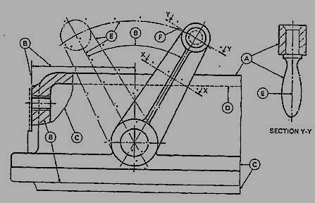
Figure 1 Types of lines
Table 2 Types of lines and their applications
Line | Description | General application |
| Continuous thick or continuous wide | Visible outlines, visible edges, main representation in diagrams, maps; system lines |
| Continuous thin (narrow) (straight or curved) | Imaginary lines of intersection; grid, dimension. Extension, projection, reference lines and hatching. |
| Continuous thin (narrow) freehand. | Limits of partial or interrupted views and sections, if the limit is not a chain thin line. |
| Continuous thin (narrow) with zigzags (straight) | Long break line |
 | Dashed thick (wide) | Line showing permissible of surface treatment. |
 | Dashed thin (narrow) | Hidden outline; hidden edges |
 | Chain thin Long-dashed dotted (narrow) | Centre line; lines of symmetry; trajectories; pitch circle of gears, pitch circle of holes. |
 | Chain thick or long - dashed (dotted) wide | Indication of lines or surfaces to which a special requirement applies. |
Line widths:
Line width means line thickness
Choose line widths according to the size of the drawing from the following range: 0.13, 0.18, 0.25, 0.35, 0.5, 0.7 and 1 mm.
Precedence of Lines
1. When a Visible Line coincides with a Hidden Line or Center Line, draw the Visible Line. Also, extend the Center Line beyond the outlines of the view.
2. When a Hidden Line coincides with a Center Line, draw the Hidden Line.
3. When a Visible Line coincides with a Cutting Plane, draw the Visible Line.
4. When a Center line coincides with a Cutting Plane, draw the Center Line and show the
Cutting Plane line outside the outlines of the view at the ends of the Center Line by thick dashes.
Let us suppose that a transparent plane has been set up between an object and the station point of an observer's eye (Fig. 1). The intersection of this plane with the rays formed by lines of sight from the eye to all points of the object would give a picture that is practically the same as the image formed in the eye of the observer. This is perspective projection.
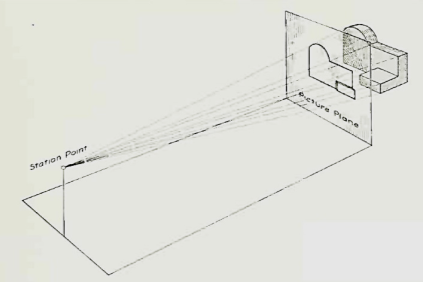
Figure 1 Perspective projection. The rays of the projection converge at the station point from which the object is observed.
If the observer would then walk backward from the station point until he reached a theoretically infinite distance, the rays formed by lines of sight from his eye to the object would grow longer and finally become infinite in length, parallel to each other, and perpendicular to the picture plane. The image so formed on the picture plane is what is known as "orthographic projection." See Fig.
2.
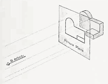
Orthographic projection.
Basically, orthographic projections could be defined as any single projection made by dropping perpendiculars to a plane. However, it has been accepted through long usage to mean the combination of two or more such views, hence the following definition has been put forward: Orthographic projection is the method of representing the exact shape of an object by dropping perpendiculars from two or more sides of the object to planes, generally at right angles to each other; collectively, the views on these planes describe the object completely. (The term "orthogonal" is sometimes used for this system of drawing.)
Orthographic views:
The rays from the picture plane to infinity may be discarded and the picture, or "view," thought of as being found by extending perpendiculars to the plane from all points of the object, This picture, or projection on a frontal plane, shows the shape of the object when viewed from the front, but it does not tell the shape or distance from front to rear. Accordingly, more than one projection are required to describe the object.
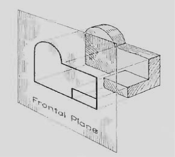
The frontal plane of projection. This produces the front view of the object.
In addition to the frontal plane, imagine another transparent plane placed horizontally above the object The projection on this plane, found by extending perpendiculars to it from the object, will give the appearance of the object as if viewed from directly above and will show the distance from front to rear.
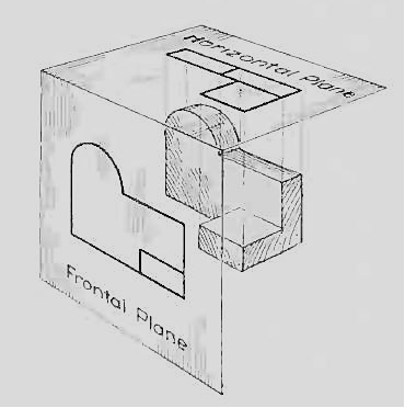
The frontal and horizontal planes of projections. Projection on the horizontal plane produces the top view of the object.
If this horizontal plane is now rotated into coincidence with the frontal plane, the two views of the object will be in the same plane, as if on a sheet of paper.
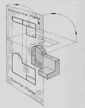
The horizontal plane rotated into the same plane as the frontal plane.
Now imagine a third plane, perpendicular to the first two. This plane is called a "profile plane," and a third view can be projected on it. This view shows the shape of the object when viewed from the side and the distance from bottom to top and front to rear.
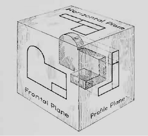
The three planes of projection: frontal, horizontal and profile. Each is perpendicular to other two.
The horizontal and profile planes are shown rotated into the same plane as the frontal plane (again thought of as the plane of the drawing paper). Thus, related in the same plane, they give correctly the three-dimensional shape of the object.
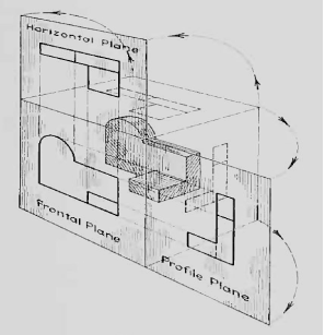
The horizontal and profile planes rotated into the same plane as the frontal plane. This makes it possible to draw three views of the object.
In orthographic projection the picture planes are called "planes of projection"; and the perpendiculars, "projecting lines" or "projectors."


