Unit 1
Diffraction and Polarization of Light
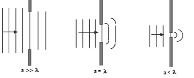
When light falls on obstacles (whose size is comparable with the wavelength of light), it bends round the corners of the obstacles and enters in the geometrical shadow. This bending of light is called diffraction.
# The amount of bending depends upon the size of the obstacle and the wavelength of wave.
# The diffraction effects are observed only when a portion of the wavefront is cut off by some obstacle.
Condition of Diffraction
The diffraction pattern is seen if the size of the diffracting obstacle is of the same order of the wavelength of light used. Diffraction is more pronounced if the size of obstacle is less than the wavelength of light.
Types of Diffraction
Diffraction phenomenon can be divided into following two general classes:
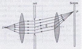
- Fraunhofer’s Diffraction:
In this class of diffraction source and the screen are placed at infinity. In this case the wavefront which is incident on the aperture or obstacle is plane.
2. Fresnel’s Diffraction:
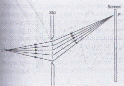
In this class of diffraction source and the screen are placed at finite distances from the aperture or obstacle having sharp edges. The incident wavefront is either spherical or cylindrical.
Difference between Fresnel and Fraunhofer's Diffractions
Fresnel Diffraction
1. Point source of light or an illuminated narrow slit is used as light source
2. Light incident on the aperture or obstacle is a spherical or cylindrical wave front
3. The source and screen are at finite distance from the aperture or obstacle producing diffraction
4. Lenses are not used to focus the rays
Fraunhofer diffraction
- Extended source of light at infinite distance is used as light source
2. Light incident on the aperture or obstacle is a plane wave front
3. The source and screen are at infinite distance from the aperture or obstacle producing diffraction
4. Converging lens is used to focus the rays
An arrangement consisting of large number of parallel slits of the same width and separated by equal opaque spaces is known as Diffraction grating.
Gratings are constructed by ruling equidistant parallel lines on a transparent material such as glass, with a fine diamond point. The ruled lines are opaque to light while the space between any two lines is transparent to light and acts as a slit. This is known as plane transmission grating. When the spacing between the lines is of the order of the wavelength of light, then an appreciable deviation of the light is produced.
Theory: A section of a plane transmission grating AB placed perpendicular to the plane of the paper is as shown in the figure.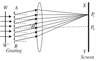
Let ‘e’ be the width of each slit and‘d’ the width of each opaque space. Then (e+d) is known as grating element and XY is the screen. Suppose a parallel beam of monochromatic light of wavelength ' ' be incident normally on the grating. By Huygen’s principle, each of the slit sends secondary wavelets in all directions. Now, the secondary wavelets travelling in the direction of incident light will focus at a point Po on the screen. This point Po will be a central maximum.
Now consider the secondary waves travelling in a direction inclined at an angle ' ' with the incident light will reach point P1 in different phases. As a result, dark and bright bands on both sides of central maximum are obtained.
The intensity at point P1 may be considered by applying the theory of Fraunhofer diffraction at a single slit. The wavelets proceeding from all points in a slit along their direction are equivalent to a single wave of amplitude starting from the middle point of the slit, Where
If there are N slits, then we have N diffracted waves. The path difference between two consecutive slits is  . Therefore, the phase difference
 ........
Hence the intensity in a direction 'v ' can be found by finding the resultant amplitude of N vibrations each of amplitude  and a phase difference of '
 '
'
Since in the previous case
Substituting these in equation
The resultant amplitude on screen at P1 becomes
 ..........
Thus, Intensity at P1 will be
 ........
The factor
Gives the distribution of Intensity due to a single slit while the factor

Gives the distribution of intensity as a combined effect of all the slits
Let us consider the resolution of two wavelengths and by a grating. When the difference in wavelengths is smaller and such that the central maximum of the wavelength coincides with the first minimum of the other as shown in figure, then the resultant intensity curve is as shown by the thick curve. The curve shows a distinct dip in the middle of two central maxima. Thus, the two wavelengths can be distinguished from one another and according to Rayleigh they are said to be “Just Resolved”.
If the difference in wavelengths is such that their principal maxima are separately visible, then there is a distinct point of zero intensity in between the two wavelengths. Hence according to Rayleigh, they are said to be “Resolved”.
When the difference in wavelengths is so small that the central maxima corresponding to two wavelengths come still closer as shown in figure, then the resultant intensity curve is quite smooth without any dip. This curve is as if there is only one wavelength somewhat bigger and stronger.
Hence according to Rayleigh, the two wavelengths are “Not Resolved”.
Thus, the two spectral lines can be resolved only up to a certain limit expressed by Rayleigh Criterion.

Resolving Power of Grating
It is defined as the capacity of a grating to form separate diffraction maxima of two wavelengths which are very close to each other
It is measured by  where
where  is the smallest difference in two wavelengths which are just resolvable by grating and
 is the wavelength of either of them or mean wavelength.

Let AB represent the surface of a plane transmission grating having grating element (e+d) and N total number of slits. Let a beam of light having two wavelengths  and
and  is normally incident on the grating. Let P1 is nth primary maximum of a spectral line of wavelength
  at an angle of diffraction
  and P2 is the nth primary maximum of wavelength
  at diffracting angle
According to Rayleigh criterion, the two wavelengths will be resolved if the principal maximum  of nth order in a direction
  falls over the first minimum of nth order in the same direction
  . Let us consider the first minimum of l of nth order in the direction
  as below.
The principal maximum of  in the
  direction is given by
 ........... (6)
The equation of minima is  where m takes all integers except 0, N, 2N, …, nN, because for these values of m, the condition for maxima is satisfied. Thus, first minimum adjacent to nth principal maximum in the direction
 can be obtained by substituting the value of ‘m’ as (nN+1). Therefore, the first minimum in the direction of
  is given by

 .. (7)
The principal maximum of  in direction
  is given by
 .......(8)
Dividing eqn(7) by eqn8), we get


 ..............(2.49)
Thus, the resolving power is directly proportional to
(i) The order of the spectrum ‘n’
(ii) The total number of lines on the grating ‘N’

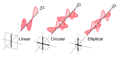
Light in the form of a plane wave in space is said to be linearly polarized. Light is a transverse electromagnetic wave, but natural light is generally unpolarized, all planes of propagation being equally probable. If light is composed of two plane waves of equal amplitude by differing in phase by 90°, then the light is said to be circularly polarized. If two plane waves of differing amplitude are related in phase by 90°, or if the relative phase is other than 90° then the light is said to be elliptically polarized
. 
Double refraction, also called birefringence, an optical property in which a single ray of unpolarized light entering an anisotropic medium is split into two rays, each traveling in a different direction. One ray (called the extraordinary ray) is bent, or refracted, at an angle as it travels through the medium; the other ray (called the ordinary ray) passes through the medium unchanged.
A birefringent substance will split unpolarized light into two polarized rays with different refractive indices and different velocities. A crystal of calcite demonstrates this phenomenon.
The optic axis of a crystal is defined by the symmetry of the lattice. In calcite CaCO3, the CO3 forms a triangular cluster, and the optic axis is perpendicular to this. If light enters along the optic axis, nothing dramatic happens and the light emerges unpolarized.
If however the light enters at an angle to this axis, the asymmetry of the lattice splits the ray into two with mutually perpendicular polarizations. One ray is called the Ordinary ray, for which Snell's law holds. The other Extraordinary ray does not obey Snell's law.
Birefringence in a calcite crystal
Observing an object through the crystal, one sees a double image. Analysis through a Polaroid sheet shows that these images have axes of polarization at right angles to each other; rotating the Polaroid makes the images alternately vanish. Things get really exciting when you place a second crystal on top of the first. Now you have fours images, but if you rotate it, it acts as an analyser for the first crystal, and you can go down to two images again.
HUYGEN’S PRINCIPLE
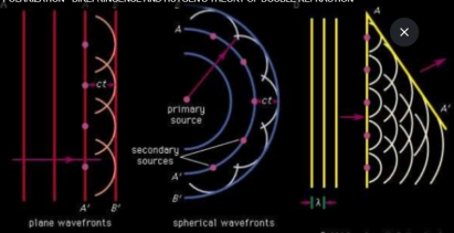
Huygens’ principle, in optics, a statement that all points of a wave front of light in a vacuum or transparent medium may be regarded as new sources of wavelets that expand in every direction at a rate depending on their velocities.
Every point on a wave-front may be considered a source of secondary spherical wavelets which spread out in the forward direction at the speed of light. The new wave-front is the tangential surface to all of these secondary wavelets.
Proposed by the Dutch mathematician, physicist, and astronomer,Christiaan hygens, in 1690, it is a powerful method for studying various optical phenomena. A surface tangent to the wavelets constitutes the new wave front and is called the envelope of the wavelets. If a medium is homogeneous and has the same properties throughout (i.e., is isotropic), permitting light to travel with the same speed regardless of its direction of propagation, the three-dimensional envelope of a point source will be spherical; otherwise, as is the case with many crystals, the envelope will be ellipsoidal in shape (see double refraction). An extended light source will consist of an infinite number of point sources and may be thought of as generating a plane wave front.

HUYGEN’S THEORY OF DOUBLE REFRACTION
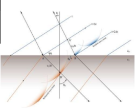
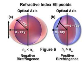
According to Huygen’s theory, a point in a doubly refracting or birefringent crystal produces 2 types of wavefronts: The wavefront corresponding to the O-ray Spherical wavefront. The ordinary wave travels with same velocity in all directions and so the corresponding wavefront is spherical. The wavefront corresponding to the E-ray Ellipsoidal wavefront oExtraordinary waves have different velocities in different directions, so the corresponding wavefront is elliptical.
WAVE SURFACES FOR NEGATIVE AND POSITIVE CRYSTALS
NEGATIVE CRYSTALS
Negative crystals are crystals in which refractive index corresponding to E-Ray (nE) is less than the refractive index corresponding to O-Ray (nO) in all directions except for Optic axis. The E-Ray travels faster than O-Ray except along the Optic axis. The spherical O-Wavefront is entirely within the ellipsoidal E -Wavefront.Ex: Calcite, Tourmaline,Ruby ...
POSITIVE CRYSTALS
Positive crystals are crystals in which refractive for O-Ray is less than that for E- Ray(nO<nE). • The velocity of O-Ray is greater than or equal to the velocity of E-Ray. • The ellipsoidal E-wavefront is entirely within the spherical O-wavefront. • Example: Quartz (SiO2), Sellaite (MgF2),Rutile(TiO2),
A material which rotates the plane of incident linearly polarized light is said to be optically active. Viewing the light head-on, some substances rotate the electric field clockwise (dextrorotatory) and some produce a counterclockwise rotation (laevorotatory). The property was discovered in quartz in 1811 by Arago. Two different crystalline structures of quartz produce d-rotatory and l-rotatory behaviour. The two crystalline forms are said to be enantiomorphs of each other. The optical activity of quartz is associated with its crystal structure, as evidenced by the fact that neither molten quartz or fused quartz demonstrate optical activity.
In the case of many naturally occurring organic compounds such as sugar, tartaric acid and turpentine, optical activity is exhibited in the liquid state. This shows that the activity is associated with the individual molecules themselves.
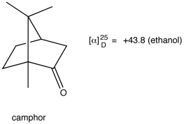
Observed rotation of an optically active compound, measured using the polarimeter, depends on the experimental conditions and, therefore, is not a characteristic property of the compound. Specific rotation (symbol: [α]λT) of an optically active compound is defined as follows:

α = observed rotation measured using a polarimeter
l = length of sample tube
C = concentration, if a solution of the compound is used for the experiment, or density, if a neat sample of the compound is used
T = Temperature (usually 25 ºC)
λ = wave length of the light used (usually 589 nm)
Specific rotation of a compound is a characteristic property of the compound as long as the temperature, the wave length of the light, and, if a solution is used for the experiment, the solvent are specified. The units of specific rotation are degreesmLg-1dm-1. However, since the units of specific rotation are always the above, traditionally, specific rotation is reported without units.
Eg:
It is used for the measurement of the angle of rotation of optically active substance in solution. That is, angle through which the plane of the polarized light is rotated on passing through a specific length of solution of known concentration.
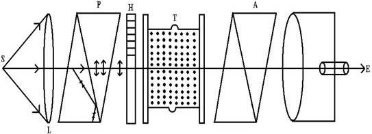
The experimental arrangement is shown if figure, S is source of monochromatic light placed at the focus of convex lens L. The beam, rendered parallel by lens L, falls on called polarizer P.
Principle
It is used for the measurement of the angle of rotation of optically active substance in solution. That is, angle through which the plane of the polarized light is rotated on passing through a specific length of solution of known concentration.
General Description
The experimental arrangement is shown if figure, S is source of monochromatic light placed at the focus of convex lens L. The beam, rendered parallel by lens L, falls on called polarizer P. After passing through polarizer P the light become plane polarized. The polarized light beam passes through a half-shale device H (called Laurent plate) and then through a tube T containing optically active solution. The transmitted light passes through another Nicol ‘A’ which can be rotated about the direction of propagation of light as axis and its rotation can be read on a circular scale graduated in degree, with the help of a Vernier.
