Unit 2
Laser and FibreOptics
Absorption is the process in which optical energy is converted to internal energy of electrons, atoms, or molecules. When a photon is absorbed, the energy may cause an electron in an atom to go from a lower to a higher energy level, thereby changing the internal momentum of the electron and the electron's internal quantum numbers. Energy in a solar cell or photodetector is then converted to electricity because the excited charge carriers can travel more freely through the material. The electrons absorbing the energy may be part of atoms which make up solids, liquids, gases, or plasmas. They may be around isolated neutral atoms, ionic compounds, or complicated organic molecules. Furthermore, the electrons absorbing the energy may be part of conductive, insulating, or semiconducting materials.
The photons absorbed may be optical photons, with individual energies in the range 1.9 to 3.1 eV that can be detected by human eyes. Alternatively, they may have energies that are multiple orders of magnitude larger or smaller than the energy of a visible photon. For example, in isolated neutral neon atoms in the ground state, electrons occupy the 2p2p energy level but not the 3s3s energy level. These energy levels are separated by an energy gap of Eg=1.96Eg=1.96 eV which corresponds with energy of red photons of wavelength 632.8 nm [31]. If a photon of this energy impinges upon neon gas, the photon may be absorbed, and an electron of a neon atom would be excited to the higher energy level.
Photons of smaller energy would not be absorbed. Photons of larger energy may be absorbed depending on allowed energy levels. As another example, the energy gap of the semiconductor gallium phosphide, GaP, is 2.2 eV which corresponds with the energy of a green photon of wavelength 549 nm. If a photon of this energy impinges on a piece of gallium phosphide, it may be absorbed.
Spontaneous emission is an energy conversion process in which an excited electron or molecule decays to an available lower energy level and in the process gives off a photon. This process occurs naturally and does not involve interaction of other photons. The average time for decay by spontaneous emission is called the spontaneous emission lifetime. For some excited energy levels this spontaneous decay occurs on average within nanoseconds while in other materials it occurs within a few seconds. As with absorption, this process can occur in isolated atoms, ionic compounds, molecules, and other types of materials, and it can occur in solids, liquids, and gases. Energy is conserved when the electron decays to the lower level, and that energy must go somewhere. The energy may be converted to heat, mechanical vibrations, or electromagnetic photons. If it is converted to photons, the process is called spontaneous emission, and the energy of the photon produced is equal to the energy deference between the electron energy levels involved. The emitted photon may have any direction, phase, and electromagnetic polarization.
There are many ways in which an electron can be excited to a higher energy level. Spontaneous emission processes may be classified based on the source of energy which excites the electrons. If the initial source of energy for spontaneous emission is supplied optically, the process is called photoluminescence. Glow in the dark materials emit light by this process. If the initial form of energy is supplied by a chemical reaction, the process is called chemiluminescence. Glow sticks produce spontaneous emission by chemiluminescence. If the initial form of energy is supplied by a voltage, the process is called electroluminescence. LEDs emit light by electroluminescence. If the initial form of energy is caused by sound waves, the process is called sonoluminescence. If the initial form of energy is due to accelerated electrons hitting a target, this process is called cathodoluminescence. If spontaneous emission occurs in a living organism, such a firefly, the process is called bioluminescence.
Stimulated emission is the process in which an excited electron or molecule interacts with a photon, decays to an available lower energy level, and in the process gives o a photon. As with the other processes, this process can occur in isolated atoms, ionic compounds, organic molecules, and other types of materials, and it can occur in solids, liquids, and gases. If an incoming photon, with energy equal to the difference between allowed energy levels, interacts with an electron in an excited state, stimulated emission can occur. The energy of the excited electron will be converted to the energy of a photon. The stimulated photon will have the same frequency, direction, phase, and electromagnetic polarization as the incoming photon which initiated the process

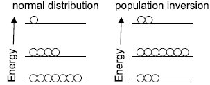
Laser pumpingis the act of energy transfer from an external source into the gain medium of a laser. The energy is absorbed in the medium, producing excited states in its atoms. When the number of particles in one excited state exceeds the number of particles in the ground state or a less-excited state, population inversion is achieved. In this condition, the mechanism of stimulated emission can take place and the medium can act as a laser or an optical amplifier. The pump power must be higher than the lasing threshold of the laser.
The pump energy is usually provided in the form of light or electric current, but more exotic sources have been used, such as chemical or nuclear reactions.
Population inversion
Under normal circumstances, the higher an energy level is, the less it is populated by thermal energy. Under some circumstances (for example, the presence of an upper energy level that has a relatively long lifetime), a system can be constructed so that there are more atoms/molecules in an upper energy level than is allowed under conditions of normal thermodynamic equilibrium. Such an arrangement is called a population inversion.
Ruby laser:
The ruby laser is the first type of laser actually constructed, first demonstrated in 1960 by T. H. Maiman. The ruby mineral (corundum) is aluminium oxide (Al2O3 ) with a small amount (about 0.05%) of chromium ions (Cr3+) which gives it its characteristic pink or red color by absorbing green and blue light.
The ruby laser is used as a pulsed laser, producing red light at 6943Å. After receiving a pumping flash from the flash tube, the laser light emerges for as long as the excited atoms persist in the ruby rod, which is typically about a millisecond.
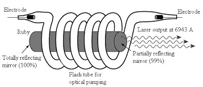
The ruby laser has following main parts:
1. The working substance (active medium)- is in the form of a rod of ruby crystal (10 cm in length, 0.8 cm in diameter) in which Cr3+ are active centres while Al and O2 are inert.
2. The resonance cavity- is made by silvering and polishing the ends of ruby rod. Fully reflecting plates at the left and a partially reflecting plate at the right, both optically plane and accurately parallel.
3. The optical pumping system -consists of a helical xenon discharge tube. It produces flash of few milliseconds.
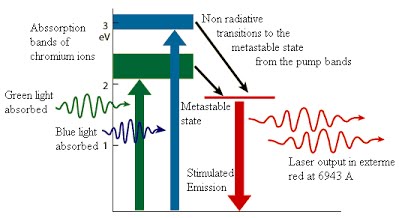
Ruby laser uses a three-level pumping scheme. The xenon discharge generates a flash of white light for few milliseconds. The Cr+3 ions are excited to the E3 level by absorbing green and blue component of white light. From there the Cr+3 ions undergo non-radiative transitions and quickly drop to the metastable level E2. The metastable state has greater life time than E3. Therefore Cr+3 ions accumulate at E2. When more than half ions are accumulated at E2 the population inversion is established between E2 and E1. A chance spontaneous emission leads to chain stimulated emission. Red light (of wavelength 6943 Å) emerges from the front face.
I Mono-chromaticity
Highly Monochromatic:
The light from a laser typically comes from one atomic transition with a single precise wavelength. So, the laser light has a single spectral color and is highly monochromatic light available.
II Coherence
Coherence:
The light from a laser is said to be coherent, which means that the wavelengths of the laser light are in phase in space and time. Large number of identical
photons are emitted through stimulated emission and therefore they will be in phase with each other.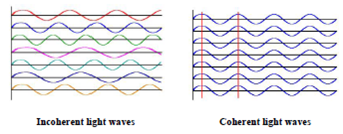
III Directionality and brightness
Highly Directional and Collimated:
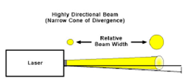
Lasers emit light that is highly directional, narrow beam divergence. The light from laser emerges in an extremely thin beam with very little divergence therefore the beam is also highly collimated.The high degree of collimation arises from the fact that the cavity of the laser has very nearly parallel
front and back mirrors which constrain the final laser beam to a path which is perpendicular to those mirrors. As a result, laser beams are very narrow and do not spread very much. Angle of divergence  ,where D is diameter of beam
IV Laser speckles
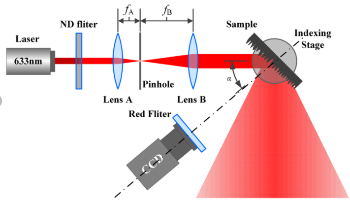
Speckle patterns can severely degrade the image quality of laser projection displays, or disturb position measurements with laser pointers. Speckle can often be avoided, e.g. By using a light source with sufficiently large optical bandwidth (short coherence length) such as a super luminescent source. (How much bandwidth is required for that purpose depends on the situation.) For projection displays, one may also work with an optimized screen. However, there are also applications of speckle, e.g. In speckle interferometry.
In conventional photography, a negative is made first and using it a positive print is produced later. The positive print is only a 2D record of light intensity received from 3D object. Only intensity of light recorded and information of phase is lost. Denis Gabor introduced a new technique where intensity and phase both are recorded. This technique is called holography. Holography is done in two stages:
1.construction of image(freezing)
A weak but broad beam of laser light is splitted into wo beams by means of beam splitter. One beam directly goes to the photographic film is called as reference beam and second beam illuminates the object called as object beam. The light scattered by the object moves towards the photographic plate and interferes with the reference beam. The photographic plate carrying complex interference pattern of the object is called hologram. The object is stored in the hologram in the form of interference pattern. Whenever required the object can be viewed by illuminating the hologram as shown in the figure 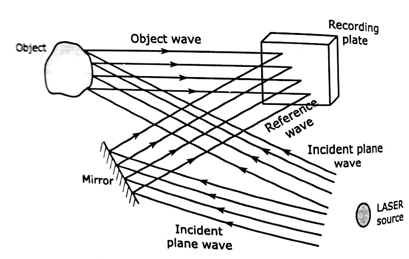
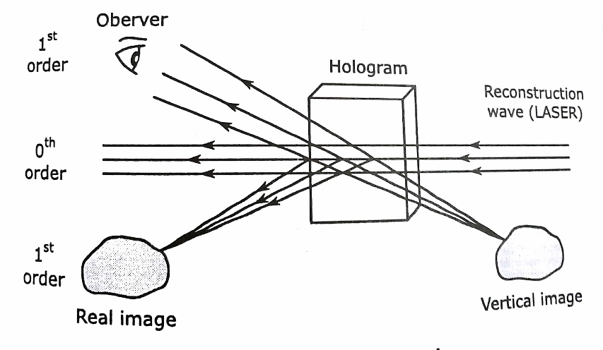
2.Reconstruction (unfreezing): A laser beam identical to the reference beam is used for reconstruction of the object. This read out bream illuminates the hologram at the same angle as the reference beam. The hologram acts as a diffraction grating and secondary waves from hologram interferes constructively in certain directions and destructively in other directions. They form a real image in front of the hologram and a virtual image behind the hologram at the original site of the object. An observer sees light waves diverging from the virtual image. An image of the object appears where the object once stood and the image is identical to what our eyes would have perceived in all its details of the object.
Fibre Optics
The phenomenon which occurs when the light rays travel from a more optically denser medium to a less optically denser medium.
Consider the following situation. A ray of light passes from a medium of water to that of air. Light ray will be refracted at the junction separating the two media. Since it passes from a medium of a higher refractive index to that having a lower refractive index, the refracted light ray bends away from the normal. At a specific angle of incidence, the incident ray of light is refracted in such a way that it passes along the surface of the water. This particular angle of incidence is called the critical angle. Here the angle of refraction is 90 degrees. When the angle of incidence is greater than the critical angle, the incident ray is reflected back to the medium. We call this phenomenon total internal reflection.
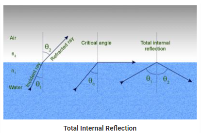

Notations Used in The Total Internal Reflection Formula and Critical Angle
- r is the angle of refraction
- i is the angle of incidence
- n1 is the refractive index in medium 1
- n2 is the refractive index in medium 2
- Ө is the critical angle
Following are the two conditions of total internal reflection:
- The light ray moves from a more denser medium to less dense medium.
- The angle of incidence must be greater than the critical angle.
When the incident ray falls on the cladding, it suffers total internal reflection as the angle formed by the ray is greater than the critical angle. Optical fibres have revolutionised the speed with which signals are transferred, not only across cities but across countries and continents making telecommunication one of the fastest modes of information transfer. Optical fibres are also used in endoscopy.
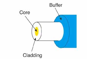
The basic structure of an optical fiber consists of three parts the core, the cladding, and the coating or buffer which are coaxially arranged. The innermost region is called the core, the light in the fibre travels only in the core. The core is surrounded by cladding, which is responsible for keeping the light inside the core. The refractive index of core (n1) is greater than of cladding (n2). The outermost region is called buffer or sheath, which protects the core and cladding from external abrasions
A) According to the number of modes
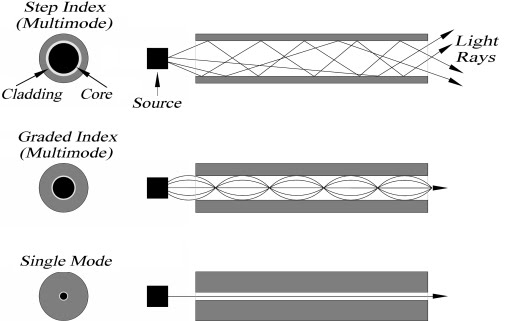
1.Single Mode fibre (SMF): The core size of single mode fibers is small. The core size (diameter) is typically around 8 to 12 micrometres and only single mode (zero order) can travel through it.
2. Multimode Fibre (MMF): The multimode fibers propagate more than one mode. The number of modes propagated depends on the core size and numerical aperture (NA). Typical values of fiber core size are 50 to 200 micrometres.
B) According to the Refractive index
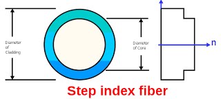
Step Index Fibre (SIF): In step index fibers, the refractive index of the core is uniform and undergoes an abrupt change at the core-cladding boundary
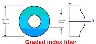
2. Graded Index Fibre (GIF): In graded index fibers, the refractive index of the core varies gradually as a function of radial distance from the fiber center
C) According to the Material
Glass-Glass Fibre: The core and cladding are both made up of glass
Plastic-Plastic Fibre: The core and cladding are both made up of plastic.
PCS Fibre: Polyester Clad Silica Fibre (PCS) has silica core cladded with polyester
The acceptance angle of an optical fiber is defined based on a purely geometrical consideration (ray optics): it is the maximum angle of a ray (against the fiber axis) hitting the fiber core which allows the incident light to be guided by the core. The sine of that acceptable angle (assuming an incident ray in air or vacuum) is called the numerical aperture, and it is essentially determined by the refractive index contrast between core and cladding of the fiber, assuming that the incident beam comes from air or vacuum:

Here, ncore and ncladding are the refractive indices of core and cladding, respectively, and n0 is the refractive index of the medium around the fiber, which is close to 1 in case of air.
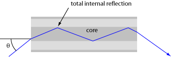
The largest Launch Angle of Incident Light that can propagate down the Fiber optics
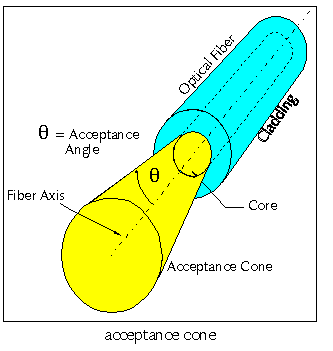
Numerical Aperture (NA)
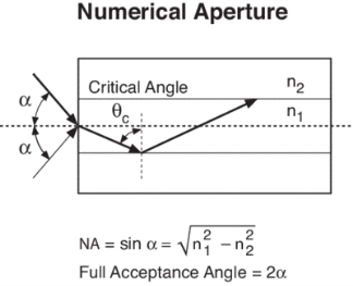
The Numerical Aperture (NA) of a fibre is defined as the sine of the largest angle an incident ray can have for total internal reflectance in the core. Rays launched outside the angle specified by a fibber’s NA will excite radiation modes of the fiber. A higher core index, with respect to the cladding, means larger NA. However, increasing NA causes higher scattering loss from greater concentrations of dopant. A fiber's NA can be determined by measuring the divergence angle of the light cone it emits when all its modes are excited.
Qualitatively, NA is a measure of the light gathering ability of a fiber. It also indicates how easy it is to couple light into a fiber.
The fractional difference Δ between the refractive indices of the core and the cladding is known as the fractional refractive index change.
It is given by

The value of Δ is always positive because n1 must be greater than n2 for the total internal reflection condition.
In order to guide light rays effectively through a fibre, Δ<<1 and Δ is of the order of 0.01
The communication system of fiber optics is well understood by studying the parts and sections of it. The major elements of an optical fiber communication system are shown in the following figure.
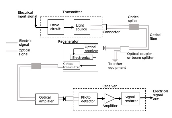
The basic components are light signal transmitter, the optical fiber, and the photo detecting receiver. The additional elements such as fiber and cable splicers and connectors, regenerators, beam splitters, and optical amplifiers are employed to improve the performance of the communication system.
Functional Advantages
The functional advantages of optical fibers are −
- The transmission bandwidth of the fiber optic cables is higher than the metal cables.
- The amount of data transmission is higher in fiber optic cables.
- The power loss is very low and hence helpful in long-distance transmissions.
- Fiber optic cables provide high security and cannot be tapped.
- Fiber optic cables are the most secure way for data transmission.
- Fiber optic cables are immune to electromagnetic interference.
- These are not affected by electrical noise.
Physical Advantages
The physical advantages of fiber optic cables are −
- The capacity of these cables is much higher than copper wire cables.
- Though the capacity is higher, the size of the cable doesn’t increase like it does in copper wire cabling system.
- The space occupied by these cables is much less.
- The weight of these FOC cables is much lighter than the copper ones.
- Since these cables are di-electric, no spark hazards are present.
- These cables are more corrosion resistant than copper cables, as they are bent easily and are flexible.
- The raw material for the manufacture of fiber optic cables is glass, which is cheaper than copper.
- Fiber optic cables last longer than copper cables.
Disadvantages
Although fiber optics offer many advantages, they have the following drawbacks −
- Though fiber optic cables last longer, the installation cost is high.
- The number of repeaters is to be increased with distance.
- They are fragile if not enclosed in a plastic sheath. Hence, more protection is needed than copper ones.
- Medical
Used as light guides, imaging tools and also as lasers for surgeries - Defence/Government
Used as hydrophones for seismic waves and SONAR, as wiring in aircraft, submarines and other vehicles and also for field networking - Data Storage
Used for data transmission - Telecommunications
Fiber is laid and used for transmitting and receiving purposes - Networking
Used to connect users and servers in a variety of network settings and help increase the speed and accuracy of data transmission - Industrial/Commercial
Used for imaging in hard to reach areas, as wiring where EMI is an issue, as sensory devices to make temperature, pressure and other measurements, and as wiring in automobiles and in industrial settings - Broadcast/CATV
Broadcast/cable companies are using fiber optic cables for wiring CATV, HDTV, internet, video on-demand and other applications
Fiber optic cables are used for lighting and imaging and as sensors to measure and monitor a vast array of variables. Fiber optic cables are also used in research and development and testing across all the above-mentioned industries.