Unit – 2
Fluid Statics& Buoyancy
To determine pressure at any point in a fluid at rest ‘hydrostatic law ‘ is used which states that ‘the rate of increase of pressure in a vertically downward direction must be equal to the specific weight of the fluid at that point.
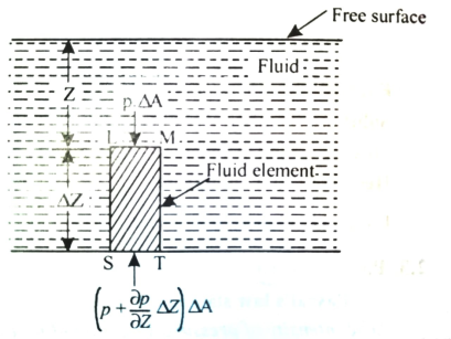
Let p = Intensity of pressure on face LM,
 Cross sectional area of the element,
Z = Distance of the fluid element from free surface,
 Height of the element,
The forces acting on the elements are:
Pressure force on the face LM = p x  …….acting downward.
Pressure force on the face ST =  x
x  ……. Acting upward
Weight of the fluid element = Weight density x Volume
= w x  x
x 
Pressure forces on the face MT & LS are equal and opposite.
For equilibrium of the fluid element,
 x
x  p x
p x  w x
w x  x
x  = 0
= 0
 - w x
- w x  x
x  = 0
= 0
 = w
= w
Above eqn states that rate of increase of pressure in a vertical direction in equal to weight density of the fluid at that point. This is hydrostatic law.
On integrating above eqn

Where p = pressure above atmospheric pressure
Z = pressure head.
w = Specific weight of liquid.
To determine pressure at any point in a fluid at rest ‘hydrostatic law ‘ is used which states that ‘the rate of increase of pressure in a vertically downward direction must be equal to the specific weight of the fluid at that point.
p = w Z
Or
Z
Where p = pressure above atmospheric pressure
Z = pressure head.
w = Specific weight of liquid.
- Atmospheric pressure:
Air exerts a normal pressure upon all surfaces with which it is in contact, and it is known as atmospheric pressure.
The atmospheric pressure is also known as Barometric pressure.
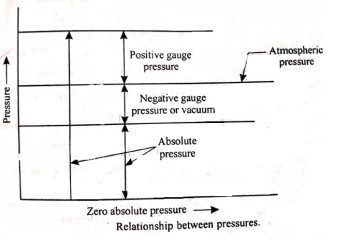
- Gauge Pressure:
It is the pressure, measured with the help of pressure measuring instrument, in which the atmospheric pressure is taken as datum.
The atmospheric pressure on the scale is marked as zero.
- Absolute pressure:
It is necessary to establish as absolute pressure scale which is independent of the changes in atmospheric pressure.
A pressure of absolute zero can exist only in complete vacuum
Any pressure measured above the absolute zero of pressure is termed as an absolute pressure.
- To determine intensity of pressure at any point on the wall or surface.
- To determine total pressure.
- To calculate total pressure on bottom tank due to different liquids on one another.
- To draw pressure diagram.
- To measure pressure.
- Manometer
Manometer are defined as the devices used for measuring the pressure at a point in a fluid by balancing the column of fluid by the same or another column of liquid.
- Simple manometers
A “simple manometer” is one which consists of a glass tube whose one end is connected to a point where pressure is to be measured and the other end remains open to atmosphere.
- Piezometer:
- A piezometer is the simplest form of manometer which can be used for measuring moderate pressures of liquids.
- It consists of a glass tube inserted in the wall of a vessel or of a pipe, containing liquid whose pressure is to be measured.
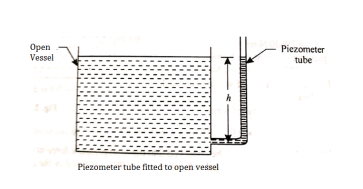
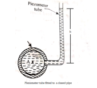
- The tube extends vertically upward to such a height that liquid can freely rise in it without overflowing.
- The pressure at any point in the liquid is indicated by the height of the liquid in the tube above that point, which can be read on the scale attached to it.
- Thus if w is the specific weight of the liquid, then the pressure at point A(p) is given by p = wh
- A piezometer tube is not suitable or measuring negative pressure; as in such a case the air will enter in pipe through the tube.
Ii. U-tube monometer:
- Piezometer cannot be employed when large pressures in the lighter liquids are to be measured, since this would require very long tubes, which cannot be handled conveniently.
- Further more gas pressures cannot be measured by piezometer because a gas forms no free atmospheric surface.
- These limitations can be overcome by the use of U-tube manometers.
- A U-tube manometer consists of a glass tube but in U-shape, one end of which is connected to a point at which pressure is to be measured and other end remains open to the atmosphere as shown in fig.
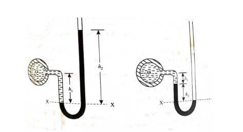
Fig (a) Fig (b)
Let A be the point at which pressure is to be measured. X-X is the datum line as shown in Fig(a)
Let, h1 = height of the light liquid in the left limb above the datum line
h2 = height of the heavy liquid in the right limb above the datum line
h = pressure in pipe, expressed in terms of head
S1 = specific gravity of the light liquid, and
S2 = specific gravity of the heavy liquid
The pressure in the left limb and right limb above the datum line X-X are equal.
Pressure head above X-X line in the left limb = h+h1S1
Pressure head above X-X in the right limb = h2S2
Equating these two pressures, we get

For negative pressure:
Refer to fig(b)
Pressure head above x-x in the left limb= 
Pressure head above x-x in the right limb = 0
Equating these two pressures, we get

Iii. Inclined Single Column Manometer:
- This type of manometer is useful for the measurement of small pressures and is more sensitive than the vertical tube type.
- Due to inclination the distance moved by the heavy liquid in the right limb is more.
l = length of the heavy liquid moved in right limb,
 = inclination of right limb horizontal, and
h2 = vertical rise of liquid in right limb from x-x = l sin

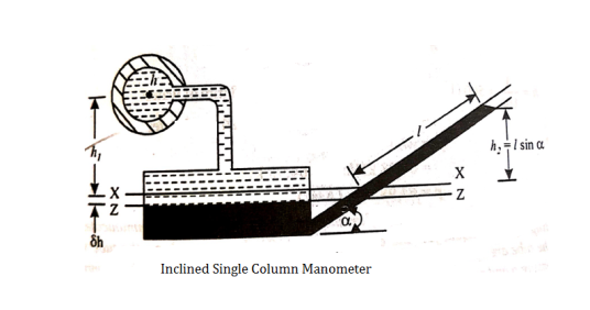
- Differential Manometers
A differential manometer is used to measure the difference in pressures between two points in a pipe or in two different pipes.
- U-tube differential manometer:
A U-tube differential manometer is shown in fig.
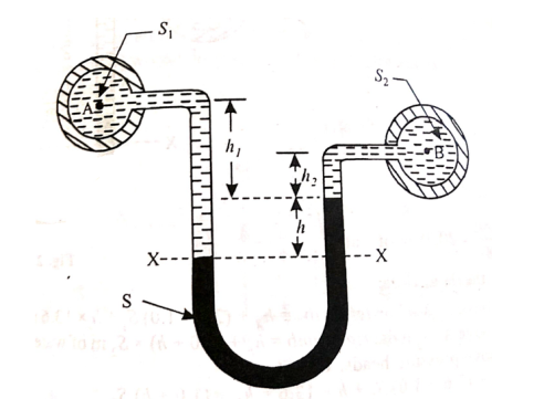
Let, h = difference of mercury level (heavy liquid) in the U-tube,
h1 = distance of the centre of A, from the mercury level in the left limb
h2 = distance of the centre of B, from the mercury level in the right limb,
S1 = specific gravity of liquid in pipe A,
S2 = specific gravity of liquid in pipe B,
S = specific gravity of heavy liquid o mercury
hA = pressure head at A,
hB = pressure head at B
Considering the pressure heads above the datum line x-x, we get
Pressure head in the left limb:

Pressure head in the right limb:

Equating the above pressure heads, we get


Ii. Inverted U-tube differential manometer:
A inverted U-tube differential manometer is shown in fig.
It consist of an inverted U tube, containing light liquid, whose two ends are connected to the points whose difference pressures is to be measured.
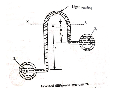
Let, h = difference of mercury level (light liquid) in the U-tube,
h1 = Height of liquid in the left limb below the datum line X-X
h2 = Height of liquid in the right limb below the datum line X-X
S1 = specific gravity of liquid in pipe A,
S2 = specific gravity of liquid in pipe B,
S = specific gravity of light liquid
hA = pressure head at A,
hB = pressure head at B
Considering the pressure heads below the datum line x-x, we get
Pressure head in the left limb:

Pressure head in the right limb:

Equating the above pressure heads, we get


2. Mechanical Gauges
- The manometers are suitable for comparatively low pressure.
- For high pressures, they become unnecessarily larger even when they are filled with heavy liquids.
- Therefore, for measuring medium and high pressures, we make use of elastic pressure gauges.
- They employ different forms of elastic systems such as tubes, diaphragms or bellows etc. to measure the pressure.
- The elastic deformation of these elements is used to show the effect of pressure. Since these elements are deformed within the elastic limit only, therefore these gauges are sometimes called elastic gauges.
- Bourdon tube pressure gauge:
- Bourdon tube pressure gauge is used for measuring high as well as low pressure.
- In this case, the pressure element consists of a metal tube of approximately elliptical cross section.
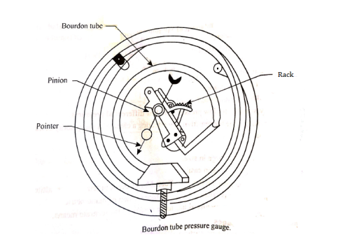
- This tube is bent in the form of a segment of a circle and responds to pressure changes.
- When one end of the tube which is attached to the gauge case, is connected to the source of pressure, the internal pressure causes the tube to expand, whereby circumferential stress is set up.
- The free end of the tube moves and is in turn connected by suitable levers to a rack, which engages with a small pinion mounted on the same spindle as the pointer.
- Thus the pressure applied to the tube causes the rack and pinion to move.
- The pressure is indicated by the pointer over a dial which can be graduated in a suitable scale.
- The Bourdon tube are generally made of bronze or nickel steel.
- The former is generally used for low pressures and the latter for high pressures.
- Diaphragm Gauge:
- This type of gauge employs a metallic disc or diaphragm instead of a bent tube.
- This disc or diaphragm is used for actuating the indicated device.
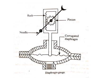
- When pressure is applied on the lower side of the diaphragm it is deflected upward.
- This movement of the diaphragm is transmitted to a rack and pinion.
- The latter is attached to the spindle of needle moving on a graduated dial.
- The dial can again be graduated in a suitable scale.
- Vacuum gauge:
- Bourdon gauges discussed earlier can be used to measure vacuum instead of pressure.
- Slight changes in the design are required in this purpose.
- Thus, in this case, the tube be bent inward instead of outward as in pressure gauges.
- Vacuum gauges are graduated in millimetres of mercury below atmospheric pressure.
- In such cases, therefore, absolute pressure in millimetres of mercury is the difference between barometer reading and vacuum gauge reading.
- Vacuum gauges are used to measure the vacuum in the condensers etc. If there is leakage, the vacuum will drop.
Total Pressure
Total pressure is defined as the force exerted by a static fluid on a surface either plane or curved when the fluid comes in contact with the surfaces. This force always acts normal to the surface.
Centre of Pressure
Centre of pressure is defined as the point of application of the total pressure on the surface. There are four cases of submerged surfaces on which the total pressure force and centre of pressure is to be determined. The submerged surfaces may be:
- Vertical plane surface
- Horizontal plane surface
- Inclined plane surface, and
- Curved surface
- Vertical plane surface
Consider a thin horizontal strip of the surface of thickness dx and breadth b.
Let the depth of the strip be x.
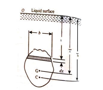
Let the intensity of pressure on strip be p.
p =wx
Total pressure on the strip = p.bdx = wx.bdx
Total pressure on the whole area P =
=w
But  = Moment of the surface area about the liquid level = A
P=wA
Moment of the pressure about free surface OO = (w.x.b. Dx).x = w.x2.b.dx
Total Moment, M = 
But  = Moment of inertia of the surface about free surface OO (I0)
Hence, M = wI0
The sum of the moment of the pressure is also equal to P× .
.
P× = wI0
= wI0
WA x
x  = wI0
= wI0
 =
= 
But 
Above eqn becomes


2. Inclined plane surface
Let A = area of the surface
 = depth of the centre of gravity from the free liquid surface.
 =angle at which the immersed surface is inclined with the liquid surface.
w=specific weight of liquid.
Consider a strip of thickness dx width b at a distance l from O.
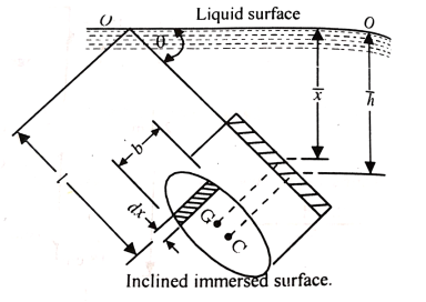
The intensity of pressure on the strip = wlsin
Area of strip = b.dx
Pressure on the strip =Intensity of pressure × area = wlsin × b.dx
Total pressure on the surface
P = 
But  Moment of surface about OO =
P= = w.
= w.
Let,  = Depth of centre of pressure below free liquid surface
IG = Moment of inertia of the immersed surface about 00.
Moment of pressure about OO = wl × l = wl2
Sum of moments about O
M = 
But  = I0 = Moment of inertia of the surface about point O
M =  Io
Io
Sum of moment of all such pressure about O is also equal to 
 = w
= w Io
Io


Where 
 (
(
= (
( 2)
2)
= +
+ 
3. Curved surface
Consider a curved immersed surface LM submerged in a static fluid as shown in fig.
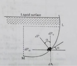
At any point on the curved surface, the pressure acts normal to the surface.
Thus, if dA is the area of a small element of the curved surface lying at a vertical depth of h from surface of the liquid, then total pressure on the elemental area is

This force dP acts normal to the surface. Further integration of above eqn would provide the total pressure on the curved surface and hence

But in case of curved surface the direction of the total pressure on the elementary areas are not in the same direction but varies from point to point.
Thus, the integration of eqn. For curved surface is impossible. The problem however, can be solved by resolving the force P into horizontal and vertical components PH and PV. Then total force on the curved surface is

Hence, the direction of the resultant force P

Where,
PH = Total pressure force on the projected area of the curved surface on vertical plane.
PV = Weight of the liquid supported by the curved surface of liquid.
- To calculate total force acting on sluice gates of dams.
- To calculate total force acting on partial or fully immersed body.
- To calculate the reaction at the hinge.
- In designing lock gates in navigation chambers.
Whenever a body is immersed wholly or partially in a fluid it is subjected to an upward force which tends to lift it up.
The tendency for an immersed body to be lifted up in the fluid due to an upward force opposite to action of gravity is known as buoyancy.
The force tending to lift up the body under such conditions is known as buoyant force or force of buoyancy.
The magnitude of the buoyant force can be determined by Archimedes principle which states as follows :
“ When a body is immersed in a fluid either wholly or partially it is buoyed or lifted up by a force which is equal to the weight of fluid displaced by the body. ”
Centre of Buoyancy
The point of application of the force of buoyancy on the body is known as the center of buoyancy. It is always the center of gravity of the volume of fluid displaced.
Stability of floating Body :
The stability of a floating body is determined from the position of Meta-centre (M).
a). Stable Equilibrium
If the point M is above G, the floating body will be in stable equilibrium as shown in Fig.
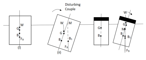
M is above G (stable equilibrium) M is below G (unstable equilibrium)
If a slight angular displacement is given to the floating body in the clockwise direction, the center of buoyancy shifts from B to B1, such that the vertical line through B1 cuts at M.
Then the buoyant force FBthrough B1 and weight W through G constitute a couple acting in the anti-clockwise direction and thus bringing the floating body in the original position.
Unstable Equilibrium :
If the point M is below G, the floating body will be in unstable equilibrium as shown in fig.
The disturbing couple is acting in the clockwise direction.
The couple due to buoyant force FB and W is also acting in clock direction and thus overturning the floating body.
Neutral Equilibrium :
If the point M is at the center of gravity of the body. The floating body will be in neutral equilibrium.
Stability of submergedBody :
The position of center of gravity ¢er of buoyancy in case of a completely submerged body are fixed.
Weight W acting vertically downward through G, while the buoyant force FB is acting vertical up through B.
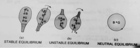
Stable Equilibrium
When W = FB& point B is above G, the body is said to be in stable equilibrium.
Unstable Equilibrium :
If W = FB , but center of buoyancy B is below the center of gravity G, the body is in unstable equilibrium.
Neutral Equilibrium :
If W = FB & point B & G are at the same point, the body is said to be in neutral equilibrium.
It is defined as the point about which a floating body starts oscillating when the body is tilted by a small angle.
The meta-center may also be defined as the point at which the line of action of the force of buoyancy will meet the normal axis of the body when the body is given a small angular displacement.
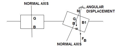
Consider a body floating in a liquid as. Let the body is in equilibrium and G is the center gravity and B is the center of Buoyancy.
Let the body is given a small angular displacement in the clockwise direction as shown in fig. The center of buoyancy, which is the center of the displaced liquid or center of gravity of portion of the body submerged in liquid, will be shifted towards right from the normal axis.
Let it is at B1 as shown in Fig.
The line of action of the force of buoyancy in this position, will intersect the normal axis of the body some point say M.
This point M is called Meta-center.
Meta-Centric Height
The distance MG,the distance between the meta-center of a floating body and the center of gravity of the body is called Meta-centric height.
Determination of Metacentric Height
- Analytical method
- Refer fig. It shows the tilted position of the floating body, the line L’ON’ represents the water surface.
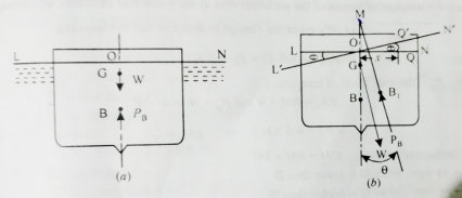
- The portion N’ON of the body is submerged and the portion L’OL is lifted because of tilting.
- As a result of this, the centre of buoyancy changes its position from B to B1.
- The intersection of axis of the body and the vertical line through B1, locates the metacentre, M of the body.
- To find the metacentre height GM consider an elementary cylindrical prism QQ’ of portion N’ON at a distance ‘x’ from O.
Let the area of this elementary prism be  A.
A.
The height of this elementary prism is given by x.Ө
The volume of this elementary prism is given by

The upward force or buoyancy for acting at this prism ( is given by

The moment of this buoyancy force about O

For the total portion N’ON, this moment is given by

Or 
Where I = moment of inertia of the sectional area at the waterline about the axis through O.
 gives the change in moment due to buoyancy.

(where PB = the total force of buoyancy)


Now metacentric height, GM=BM  BG
BG
2. Experimental model
- In this method, a known weight W1 is shifted by a distance, z across the axis of tilt.
- The change of moment due to this shift is W1z
- Let the angle of tilt be Ө.
- This angle of tilt may be measured experimentally by using a plumb bob.
- The change in moment due to this tilt is equal to W.GG1 or W.GM tanӨ.
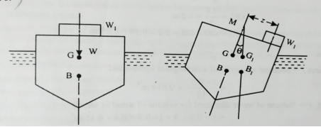

If, l = length of plumb bob, and
d = displacement of the plumb bob,
Then, 
And metacentric height is given by,

Numerical:
1] A rectangle plane surface is 2 m wide & 3 m deep. It lies in vertical plane in water. Determine the total pressure & position of centre of pressure when its upper edge is horizontal & a) Coincides with water surface
b) 2.5 m below the free water surface.
Given
b = 2m
d = 3m
a). Upper edge coincides with water surface
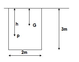
A = b x d = 2 x 3 = 6 m2
X = d/2 -3/2 = 1.5 m
Total Pressure
F = AX
= 9810 x 6 x 1.5
= 88290 N
IG = bd3/12 = 2 x 33/12 = 4.5 m4
Centre of Pressure
h = IG/AX + X = 4.5/(6 x 1.5) + 1.5 = 2m
b). Upper edge 2.5 m below water surface
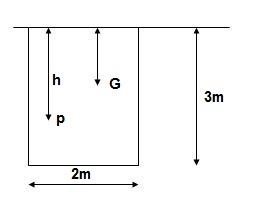
X = 2.5 + 3/2 = 4m
Total pressure F = Ax
= 9810 x 6 x 4
= 235440 N
h = IG/AX + X = 4.5/(6 x 4) + 4 = 4.1875 m
2]. A heavy car plunges into a lake during an accident & land at the bottom of the lake on its wheel. The door is 1.2 m high & 1m wide, the top edge of the door is 8m below the free surface of the water. Determine total pressure acting on door approximating it as a vertical rectangular plate ¢re of pressure.
Given Find
b = 1 m F, h
d = 1.2 m
A = b x d = 1 x 1.2 = 1.2 m2
X = 8 + d/2 = 8 + 1/2/2 = 8.6 m
F = AX
= 9810 x 1.2 x 8.6
= 101.24 x 10³ N
IG = bd3/12 = 1 x 1.23/12 = 0.144 m4
h = IG/AX + X = 0.144/(1.2 x 8.6) + 8.6 = 8.614 m
3]. A circular plate 1.5 m diameter is submerged in water with its greatest & least depth below the surface being 2 m & 0.75 m respectively. Determine total pressure ¢re of pressure.
Given Find
d = 1.5 m F, h
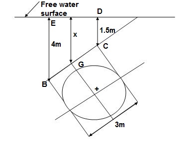
1). A = π/4 x d2 = π/4 x 1.52 = 1.767 m2
2). X = Greatest depth + Least depth / 2
= (2 + 0.75)/2 = 1.375 m
3). F = AX
= 9810 x 1.767 x 1.375
= 28.83 x 10³ N
4). Sin = 1.25/1.5 = 0.833
5). IG = π/64 x d4 = π/64 x 1.54 = 0.248 m4
6). h = IG Sin2/AX + X
0.248 x 0.8332/1.767 x 1.375 + 1.375
= 1.446 m
4]. A triangular plate of 1m base & 1.5 m altitude is immersed in water. The plate is inclined at 300 with free water surface & base is parallel to & at a depth of 2 m from water surface. Find total pressure ¢re of pressure.
Given Find F, h
b = 1 m
h = 1.5 m
= 300
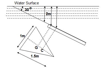
A = ½ x b x h = ½ x 1 x 1.5 = 0.75 m2
X = 2 + 1.5/3 x Sin 30 = 2.25 m
F = AX
= 9810 x 0.75 x 2.25
= 16.55 x 10³ N
IG = bh3/36 = 1 x 1.53/36 = 0.09375 m4
h = IGSin2/AX + X
= 0.09375 x (Sin 30)2/0.75 x 2.25 + 2.25
= 2.264 m
5]. A solid cylinder of diameter 4m and height 4 m. Find the metacentric height of the cylinder if the specific gravity of cylinder is 0.6 and it is floating in water with its axis vertical. State whether the equilibrium is stable or unstable.
Soln. D=4m
H=4m
S=0.6
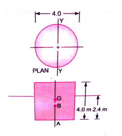
Depth of cylinder in water = 0.6H = 0.6(4) = 2.4m
Distance of centre of buoyancy(B) from A
AB = 2.4 / 2 = 1.2m
Distance of centre of gravity (G) from A
AG = H / 2 = 2m
BG = AG – AB = 2 – 1.2 = 0.8m
I =  4
4
V = Volume of cylinder in water
=
Metacentric height GM = (I / V) – BG
= (12.56/30.16) – 0.8
= -0.383 m
Negative sign means that the metacentre M is below the centre of gravity G. Thus, the cylinder is in unstable equilibrium.
6] A differential manometer is connected to at two points A and B of two pipes as shown in fig. Pipe A contains liquid of specific gravity 1.6, while pipe B contains liquid of specific gravity 0.8. If the pressure at A and B are 11.8×10⁴ N/m² and 19.60× 10⁴ N/m², find the difference in Mercury level in differential manometer.
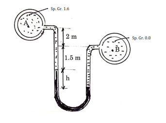
Soln. S1 =1.6
S2 = 13.6
S3 = 0.8
PA = 11.8 ×10⁴ N/m²
PB =19.60× 10⁴ N/m²
h1 = 3.5m h2 = h h3 = h+1.5
PB – PA = w (hB – hA)
19.60× 10⁴ - 11.8 ×10⁴ = 9810 (hB – hA)
hB – hA= 7.95m
Pressure in left limb above datum line = Pressure in right limb above datum line
hA+h1s1+h2s2 = hB+h3s3
h1s1+h2s2-h3s3 = hB - hA
3.5×1.6+h(13.6)-(h+1.5)0.8 = 7.95
h = 0.28m
7] An inverted differential manometer having an oil of specific gravity 0.75 was connected to two different types carrying water under pressure as shown in figure. Determine the pressure in the pipe B in terms of kPa, if manometer reads as shown in figure. Take pressure in the pipe A as 1.5 m of water.
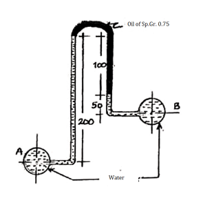
Soln. S1 =1 S2=0.75 S3=1
h1=0.2m h2=0.1m h3=0.05m hA=1.5m
Pressure in left limb below datum line = Pressure in right limb below datum line
hA - h1s1 =hB - h2s2-h3s3
1.5 – 0.2×1 = hB - 0.1×0.75-0.05×1
HB = 1.425m
PB = whB = 9810 ×1.425 = 13979.25 N/m2
Reference:
1. Fluid Mechanics& Hydraulics Machines- R.K. Bansal
2. Fluid Mechanics –R.K. Rajput