Unit -5
Laminar flow & boundary layer theory
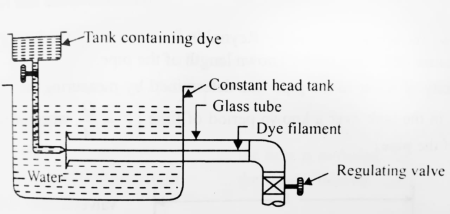
Refer to fig. Reynolds experiment apparatus consisted essentially of the following:
1) A constant head tank filled with water.
2) A small tank containing dye (Sp. Weight of dye same as that of water).
3) A horizontal glass tube provided with a bell mouthed entrance
4) A regulating valve.
Procedure followed
- The water was made to flow from the tank through the glass tube into the atmosphere and the velocity of flow was varied by adjusting valve.
- The liquid dye was introduced into the flow at the bell mouth through a small tube as shown in fig.
Observation made:
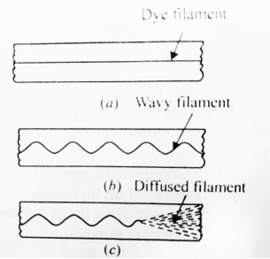
1) When the velocity of flow was low, the dye remained in the form of straight and stable filament passing through the glass tube so steadily that is scarecely seemed to be inmotion. This was a case of laminar flow as shown in figure(a)
2) With the increase of velocity, a critical state was reached at which dye filament showed irregularities and began to waver. Fig b
This shows that the flow is no longer a laminar one. This was a transitional state.
3) With further increase in velocity of the flow, the fluctuations in the filament of dye became more intense and ultimately the dye diffused over the entire cross section of the tube due to the intermingling of the particles of the flowing fluid.
This was the case of a turbulent flow as shown in figure c.
On the basis of his experiment, Reynolds discovered that:
1) In case of laminar flow, the loss of pressure head is directly proportional to velocity.
2) In case of turbulent flow, the loss of head is directly proportional to square of velocity.
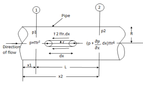
Fig: Shows a horizontal circular pipe of radius R, having laminar flow of fluid through it.
Consider a small concentric cylinder of radius r and length dx as a free body.
If  is the shear stress, the shear force F is given by
F =  x 2
x 2  r x dx
Let P be the intensity of pressure at left end and the intensity of pressure at the right end be (
Thus, the force acting on the fluid element are:
i) the shear force,  x 2
x 2 r x dx on the surface of fluid element.
Ii) The pressure force, P x  on the left end.
Iii) The pressure force, ( on the right end.
For steady flow, the net force on the cylinder must be zero.
 [ p x
[ p x  - (
- ( ] –
] – 
 -
-  -
-

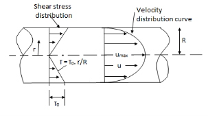
Shear stress is zero at the centre of pipe (r = 0) and maximum at the pipe wall given by
 (
( )
)
From Newton’s Law of viscosity.

In this equation, the distance y is measured from the boundary. The radial distance r is related to distance y by the relation.
y = R-r ordy = -dr

Comparing two values of 
 =
= 
 du =
du =  (
( )r.dr
)r.dr
Integrating the above equation w. r. t. ‘r’ we get
 u =
u =  .
.  r2 + C --------------- (ii)
Where C is the constant of integration and its value is obtained from the boundary conditions.
At r = R, u = 0
 0 =
0 =  .
.  R2 + Cor C =
  .
.  R2
R2
Substituting this value of C in eqn. (ii) we get,
 u =
u =  .
.  r2
r2 .
.  R2
R2
 u = -
u = -  .
.  (R2 – r2)
Shows that velocity distributioncurve is a parabola.
The maximum velocity occurs, at the centre and is given by.
 umax = -
  R2
R2
Flow of viscous fluid between two parallel plates when one plate is moving & other of Rest – Coutte flow
Consider laminar flow between two parallel flat plates located at a distance b apart such that lower plate is at rest & the upper plates moves uniformly with a constant velocity U as shown in fig.
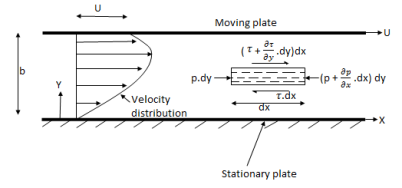
A small rectangular element of fluid of length dx, thickness dy& unit width is
Considered as a free body.
The forces acting on the fluid element are
1) The pressure force p dy x 1 on left end
2) The pressure force (p + . Dx) dy x1 on the right end.
3) The shear force 
4) The shear force [ . Dy] dx x 1 on the surface.
For steady & uniform flow the resultant force in the direction of flow is zero.
p. Dy – (p +  . Dx) dy –
  + (
+ ( +
+ . Dy) dx = 0
- dx. Dy +
  dy. Dx = 0
Dividing by the volume of element dx. Dy we get
 =
=  -------------------(1)
Above equation shows the interdependence of shear & pressure gradients
According to Newton’s law of viscosity for laminar flow the shear stress.
 =
=  .
. 
Put in equation (1) we get,
 =
= 
Integrating above equation twine w.r.t. y
u =  y2 + C1 y + C2 -------------(2)
At y = 0, u = 0 & at y = b, u = U
We get C2 = 0 & C1 =  -
-  (
( ) b
) b
Put values of C1& C2 in eqn. (2)
u =  y -
y -  (by – y2)
q =  =
=  (by – y2)] dy
U.  -
- 
The distribution of shear stress across any section may be determined by using
Newton’s Law of viscosity
 = u.
= u.  =
=  [
[ -
-  (
( ) (b – 2y)]
=  -
-  (b – 2y)
Both Plates at Rest:
In this case the equations for velocity, discharge q and the shear can be obtained from similar equation for generalises Coutte flow by putting U = 0
Thus, for flow between two stationary parallel plates.
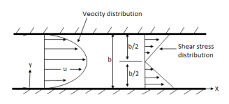
u = -  .
.  (by – y2)
Discharge per unit width,
q =  .
. 
Shear stress  .
.  (b –2y)
1. Rotating cylinder method
- In this method, Newton’s law of viscosity is used to measure the viscosity of a fluid.
- Figure shows a rotating cylinder viscometer.
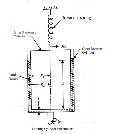
- It consists of two concentric cylinders, the annular space between them is filled with the liquid whose viscosity is to be determined.
- The outer cylinder is rotated at a constant angular velocity with respect to the inner stationary cylinder.
- The torque transmitted by the enclosed liquid to the stationary cylinder is measured by the torsional strain of the restraining spring attached to the top of the inner cylinder.
According to Newton’s law of viscosity,

Since the annular space t = (R2 – R1) is quite small (where R2 and R1 are the radii of the outer and inner cylinders respectively), the velocity gradient

(where N= the rotational speed of the outer cylinder in rpm)
Shear stress =
= 
Viscous drag = Shear stress × Area
= 
(where h = height of liquid)
Viscous torque = Viscous drag x radius
= x
x 
Viscous torque must be equal to the torque T exerted by the torquemeter.


Thus, a rotational type viscometer can be calibrated to directly give u for given speed of rotation N.
2. Falling Sphere Method
- Falling sphere method of measuring viscosity of a liquid is based on Stokes law.
- Figure shows a falling sphere viscometer.
- A small spherical ball is released into the liquid to be tested and it accelerate under the gravitational force until it reaches a maximum terminal velocity V when the buoyant and viscous drag forces balance the gravity force.
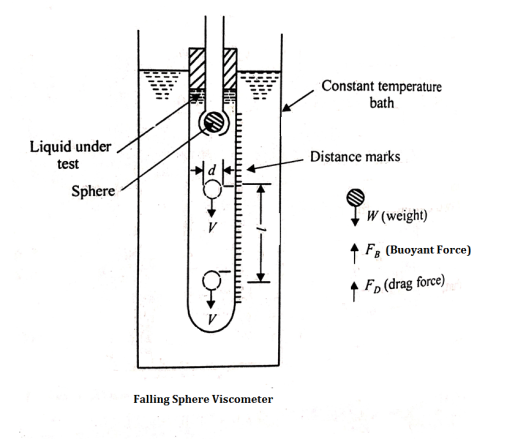
d = Diameter of the spherical ball.
l = distance travelled by the sphere in viscous liquid.
t = Time taken by the sphere to cover distance l
 = Density of sphere
 = Density of fluid/liquid
W = weight of sphere
FB = Buoyant force acting on the sphere
FD = Drag force, and
 = Dynamic viscosity of the liquid under test.
The force acting on the sphere are-
1) Weight W, acting vertically downward.
2) Buoyant force FB, acting vertically upward
3) Drag force FD, acting vertically upward.
W= volume × Density of sphere × g
=
FB = weight of liquid displaced
= volume of liquid displaced × density of liquid × g
=
FD = 3 VD
VD
For equilibrium
FD + FB = W
FD = W – FB
3 VD =
VD =  -
-  =
= 
 =
= 
From the above eqn the value of dynamic viscosity u can be determined.
3. Redwood viscometer
- The redwood viscometer consist of vertical cylindrical oil cup with an orifice in the centre of its base.
- The orifice can be closed by a ball.
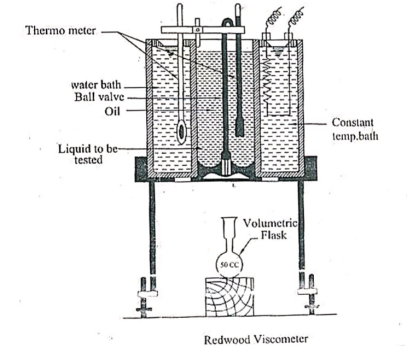
- A hook pointing upward serve as a guide mark for filling the oil.
- The cylindrical cup is surrounded by the water bath .
- The water bath maintain the temperature of the oil to be tested at constant temperature .
- The oil is heated by heating the water bath by means of an immersed electric heater in the water bath.
- The provision is made for stirring the water , to maintain the uniform temperature in the water bath and to place the thermometer to record the temperature of oil and water bath .
- This viscometer is used to determine the kinematic viscosity of the oil. From the kinematic viscosity the dynamic viscosity is determined
- Darcy’s law states the principle which governs the movement of fluid in the given substance.
- Darcy’s law equation that describes the capability of the liquid to flow via any porous media like a rock.
- The law is based on the fact according to which, the flow between two points is directly proportional to the pressure differences between the points, the distance and the connectivity of flow within rocks between the points. Measuring the interconnectivity is known as permeability.
Darcy’s Law Application
- One application of Darcy’s law is to flow water through an aquifer.
- Darcy’s law with the conservation of mass equation is equivalent to the groundwater flow equation, being one of the basic relationships of hydrogeology.
- Darcy’s law is also applied to describe oil, gas and water flows through petroleum reservoirs.
- The liquid flow within the rock is governed by the permeability of the rock.
- Permeability has to be determined in horizontal and vertical directions.
- For instance, shale consists of improbabilities which are less vertically.
- This indicates that it is not easy for liquid to flow up and down via shale bed but easier to flow side to side.
Darcy’s Law Equation
- To understand the mathematical aspect behind liquid flow in the substance, Darcy’s law can be described as:
- Darcy’s law describes the relationship among the instantaneous rate of discharge through porous medium and pressure drop at a distance.
- Using the specific sign convention, Darcy’s law is expressed as:
Q = -KA dh/dl
Wherein:
Q is the rate of water flow
K is the hydraulic conductivity
A is the column cross section area
Dh/dl indicates hydraulic gradient.
Limitations of Darcy’s Law
Darcy’s law can be applied to many situations but do not correspond to these assumptions.
- Unsaturated and Saturated flow.
- Flow in fractured rocks and granular media.
- Transient flow and steady-state flow.
- Flow in aquitards and aquifers.
- Flow in Homogeneous and heterogeneous systems.
- Turbulent flows can often be observed to arise from laminar flows as the Reynolds number is increased1.
- The transition to turbulence happens because small disturbances to the flow are no longer damped by the flow, but begin to grow by taking energy from the original laminar flow.
- Laminar flows are solutions of the Navier-Stokes equations in the limit when nonlinearities can be neglected.
- This situation corresponds to the Stokes approximation; the flow is given by a balance between external forcing (mechanical or thermodynamically) and dissipation.
- The corresponding velocity field is entirely predictable and has the same regularity properties as the applied external forces.
- As the Reynolds number is increased, nonlinearities are no longer negligible.
- There is a critical Reynolds number, above which the system bifurcates toward completely new solutions.
- These solutions correspond to breaking of symmetries of the original flow.
- When the Reynolds number is increased even further, the flow that emerged after the primary bifurcation can itself become unstable to new modes breaking new symmetries.
- The set of bifurcation continues until the global dynamics of the flow becomes very complicated, i.e. turbulent.
- When a real fluid flows past a stationary solid boundary, a layer of fluid which comes in contact with the boundary surface, adheres to it & condition of no slip occurs.
- Thus the layer of fluid which cannot slip away from the boundary surface undergoes retardation.
- This retarded layer further causes retardation for the adjacent layers of fluid, thereby developing a small region in the intermediate vicinity of boundary surface in which the velocity of fluid increases rapidly from zero at the boundary surface & approaches the velocity of main stream.
- The layer adjacent to the boundary is known as boundary layer.
- Boundary layer is formed whenever there is relative motion between the boundary & the fluid.
Laminar, transitional and turbulent boundary
Layer
Laminar Boundary Layer
- Consider the flow of fluid having free stream velocity(U) over a smooth thin plate which is flat and placed parallel to the direction for free stream of fluid as shown in the figure.
- Let us consider the flow with zero pressure gradient on one side of the plate which is stationary.
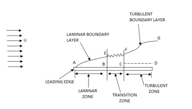
- The velocity of the fluid on the surface of the plate should be equal to the velocity of the plate. But plate is stationary and hence velocity of fluid on the surface of the plate is zero. But at a distance away from the plate, the fluid is having certain velocity.
- Thus, a velocity gradient is setup in the fluid near the surface of the plate. This velocity gradient develops shear resistance, which retards the fluid.
- Thus, the fluid with a uniform free stream velocity(u) is retarded in the vicinity of the solid surface of the plate and the boundary layer region begins at the sharp leading edge.
- At subsequent points downstream the leading edge, the boundary layer region increases because the retarded fluid is further retarded.
- This is also referred as the growth of boundary layer.
- Near the leading edge of the surface of the plate, where the thickness is small, the flow in the boundary layer is laminar though the main flow is turbulent.
- This layer of the fluid is said to be laminar boundary layer. This is shown by AE in figure.
Turbulent Boundary Layer
- The thickness of the boundary layer will go on increasing in the downstream direction.
- Then the laminar boundary layer becomes unstable and motion of fluid within it is disturbed and irregular which leads to a transition from laminar to turbulent boundary layer.
- This short length over which the boundary layer flow changes from laminar to turbulent is called transition zone. This is shown by distance BC in figure.
- Further downstream the transition zone, the boundary layer is turbulent and continues to grow in thickness. The layer of boundary is called turbulent boundary layer, which is shown by the portion FG in figure.
Boundary Layer Thickness ( )
)
- It is defined as the distance from the boundary of the solid body measured in the y-direction to the point, where the velocity of the fluid is approximately equal to 0.99 times the free stream velocity(u) of the fluid.
- It is denoted by the symbol

1.  = Thickness of laminar boundary layer,
2.  = Thickness of turbulent boundary layer, and
3.  = Thickness of laminar sublayer.
Displacement Thickness( )
)
- It is defined as the distance, measured perpendicular to the boundary of the solid body, by which the boundary should be displaced to compensate for the reduction in flow rate on account of boundary layer formation.
- It is denoted by
 .
. - It is also defined as “The distance perpendicular to the boundary, by which the free stream is displaced due to the formation of boundary layer”.

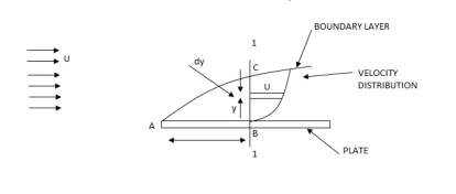
Momentum Thickness (
- Momentum thickness is defined as the distance, measured perpendicular to the boundary of the solid body, by which the boundary should be displaced to compensate for the reduction in momentum of the flowing fluid on account of boundary layer formation.
- It is denoted by


Energy Thickness ( )
)
- It is defined as the distance measured perpendicular to the boundary of the solid body, by which the boundary should be displaced to compensate for the reduction in kinetic energy of the flowing fluid on account of boundary layer formation.
- It is denoted by


- For turbulent flow analysis along a boundary, the flow is divede into two portions.
- The first portion consists of thin layer of fluid in the immediate neighbourhood of the boundary, where viscous shear stress predominates while the shear stress due to turbulence is negligible.
- This portion is known as laminar sub layer.
- It is denoted by

Local coefficient of drag (CD*)
It is defined as the ratio of the shear stress  to the quantity
It is denoted by CD*

Average coefficient of Drag (CD)
It is defined as the ratio of total drag force to the quantity 
It is also called coefficient of drag and is denoted by CD.

Where A= area of the surface (or plate)
V = free stream velocity
 = mass density of fluid
- If K is the arrange height of the irregularities of the surface of a boundary, then in general the boundary is said to be rough if value of K is high and smooth if K is low.
- For proper classification of smooth and rough boundaries, besides the boundary characteristics, the fluid and fluid characteristics need to be considered.
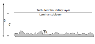
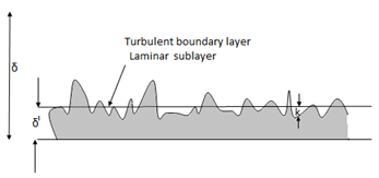
- As shown in fig: when the average height K of the irregularities is much less than the thickness of the laminar sublayers
 the flow outside the laminar sublayer is turbulent; the eddies of various sizes present, try to penetrate the laminarsublayer.
 - These eddies cannot reach the surface irregularitiesdue to greater thickness of the laminar sublayerand so the boundary acts as a smooth boundary.
- As the Reynolds numbers (Re) increases the thickness of the sublayer decreases the irregularities will then project through laminar sublayer andeventually the laminas sublayer is destroyed completely.
- Subsequently the eddies will come in contact with the surface irregularities and there will be a large amount of energy loss.
- This type of boundary is known as hydrodynamically rough boundary.
- Through experiment Nikuradse found that the boundary behave as :
i) Hydrodynamically smooth boundary, when ( ) < 0.25
Ii) Hydrodynamically rough boundary, when ( ) > 6.0
Iii) Boundary in transition, when 0.25 < ( ) < 6.0
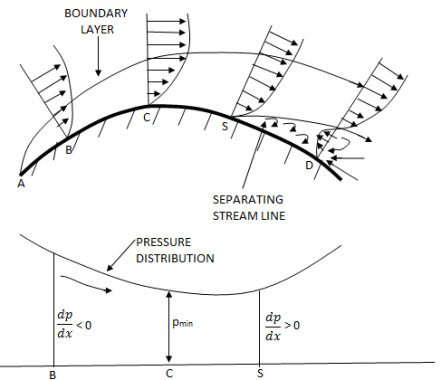
Separation of boundary layer
- When a solid body is immersed in a flowing fluid, a thin layer of fluid called the boundary layer is formed adjacent to the solid body.
- Along the length of the solid body the thickness of the boundary layer increases.
- The fluid layer adjacent to the solid surface has to do work against surface frictional at theexpense of its kinetic energy.
- This loss of kinetic energy is recovered from the immediate fluid layer in contact with the layer adjacent to solid surface through momentum exchange process.
- Thus, the velocity of the layer goes on decreasing along the length of the solid body.
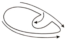
- At a certain point a stage may come when the boundary layer may not be able to keep sticking to the solid body if it cannot provide kinetic energy to overcome the resistance offered by the solid body. The boundary layer will be separated from the surface.
- This phenomenon is called boundary layer separation.
- The point on the body at which the boundary layer is on the verge of separation from the surface is called point of separation.
Methods of preventing the separation of boundary layer
The following are the methods of preventing the separation of boundary layer:
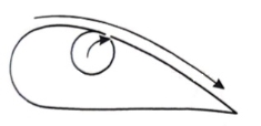
- Motion of solid boundary:
By rotating a circular cylinder lying in a stream of fluid so that the upper side of cylinder where the fluid as well as the cylinder move in the same direction, the boundary layer does not form.

2. Acceleration of fluid in the boundary layer:
This method of controlling separation consists of supplying additional energy to particles of fluid which are being retarded in the boundary layer. This may be achieved either by injecting the fluid into the region of boundary layer from the interior of the body with the help of some available device as shown in the figure or by diverting a portion of fluid of the mainstream from the region of high pressure to the retarded region of boundary layer through a slot provided in the body.
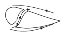
3. Suction of fluid from the boundary layer:
In this method, the slow moving fluid in the boundary layer is removed by suction through slots or through a porous surface as shown in the figure.
4. Streamlining of the body shapes:
By the use of suitable shaped bodies, the point of transition of the boundary layer from laminar to turbulent can be moved downstream which results in the reduction of the skin friction drag. Furthermore, by streamlining of the body shapes the separation may be eliminated.
5. Supplying additional energy from a blower.
6. Rotating boundary in the direction of flow.
7. Providing small divergence in a diffuser.
8. Providing guide blades in a bend.
9. Providing a trip wire ring in the laminar region for the flow over a sphere.
Numerical:
1) A Fluid of viscosity 8 poise & sp.gr. 1.2 is through a circular pipe of diameter 100mm. The maximum shear stress at the pipe u is z 10 N/M2 Find
(i) The pressure gradient
(ii) The average velocity
(iii) Reynolds number of flow
Given Find
 = 8 poise= 0.8 N.S/m2
  ,
, 
S = 1.2
 = 1.2 x1000 = 1200 kg/m3
 = 0.1 , R = 0.05 m
 = 210 N/m2
1)  o =
o = 
210 =  .
. 
 = -8400 N/m2 per m
2) The average velocity
 =
=  Umax
Umax
=  [
[ R2]
R2]
=  [ -
[ -  ]
]
= 3.28 m/s
3) Reynolds number
Re = =
= 
= 492
2) A Lubricating oil of viscosity 1 poise & sp. Gr 0.9 is pumped through a 30mm diameter pipe. If the pressure drop per meter length of pipe is 20KN/m2 determine
i) The mass flow rate in kg/min
Ii) The shear stress at the pipe wall
Iii) The Reynold number of flow
Iv) The power required per some length of the pipe to maintain the flow
Given, Find
 = 1 poise = 0.1 N.S/m2 Mass flow rate,
 0.9
0.9  o, Re, P
 = 0.9 x 1000 = 900kg/m3
 = 0.03 ,
 = (P1 – P2) = 20 x
  N.S/m2
(P1 – P2) = 
20 x  =
= 
 = 5.625 m/s
A =  x
x  =
=  x
x = 7.068 X
Q = A.  = 7.068 x
  x 5.625= 3.97 x
  /sec
/sec
Mass flow rate = 
= 900 x 3.97 x  x 60
x 60
= 214.65 kg/min
 =
= 
= 20 x  x
x 
= 150 
Reynolds Number
Re =  =
=  = 1518.7
Loss of head hf =  =
=  =2.265 m
Power =  hf
hf
= ( 0.9 x 9810 x 3.97 x  x 2.265)
= 79.49 watts
For 50m length power required
P = 79.49 x 50
= 3974.5 watts.
3) A 0.2 m diameter pipe carries liquid in laminar region. A pilot tube placed in the flow at a radial distance of 6 cm from the axis of the pipe indicates velocity of 0.5 m/s. Calculate the maximum velocity, mean velocity & discharge in the pipe.
Given, Find
D = 0.2 m, R = 0.1 m. Umax,  , Q
, Q
u(6cm) = 0.5 m/s
r = 6 cm = 0.06m
u = -  (
( )
)
0.5 = -  (
( )
)
-  = 78.125
Umax = - 
= 78.125 x 
= 0.7812 m/s
 =
=  Umax=
Umax=  0.7812
= 0.3906 m/s
A =  x
x  =
=  X
X  = 0.0314
Q = A.u
= 0.0314 x 0.3906
= 0.01227  /s
/s
4) Water is flowing over a thin smooth plate of length 4 m and breadth 2m at a velocity of 1.0m/s. If the boundary layer flow changes from laminar to turbulent at a Reynolds number 5× 10⁵;. Find
i) the distance from leading edge up to which boundary layer is laminar.
Ii) The thickness of the boundary layer at the transition point.
Iii) The drag force on one side of the plate
u = 9.81× 10⁻⁴ NS /m2
Soln. L=4m b=2m U=1.0m/s Re = 5×10⁵ u = 9.81×10⁻⁴ Ns/m2
(i) 


(ii) 
(iii) Drag force due to laminar boundary


Drag force due to turbulent boundary layer from F to G.
(FFG)turb = Drag force due to turbulent
Boundary layer E to G – Drag force due to turbulent flow from E to F.
=(FEG)turb – (FEF)turb


Drag force on one side of plate = Drag force due to laminar boundary layerupto F + Drag force due to turbulent boundary layer from F to G.
=0.92 + 11.163 = 12.083 N
5) Find the displacement thickness, the momentum thickness and energy thickness for the velocity distribution in the boundary layer given by  , where u is the velocity at a distance y from the plate and u=U at y=
 , where
  is boundary layer thickness. Also calculate the value of
  .
.
Soln. Velocity distribution 
(i) Displacement thickness is given by the equation
 =
=  (Since
 )
)
=  =
=  =
= =
=
(ii) Momentum thickness  is given by the eqn

Substituting the value of  ,
,
 =
= 

(iii) Energy thickness is given by the equation:
 =
= 
= =
=  =
=  -
-  =
= 

6) Find the displacement thickness and energy thickness for the velocity distribution in the boundary layer given by  2
2 .
.
Soln. Velocity distribution  2
2 .
.
(i) Displacement thickness is given by the equation
 =
=  (Since
  )
)


(ii) Momentum thickness  is given by the eqn
 =
= 


(iii)  =
= 
=


7) A jet plane which weighs 29.43kN and having a wing area of 20 flies at a velocity of 950km/hr when the engine delivers 7357.5kW power. 65% of the power is used to overcome the drag resistance of the wing. Calculate the coefficients of lift and drag for the wing. The density of the atmospheric air is 1.21kg/
W=29.43  N
N
A=20
U=950 km/h=950 = 263.88 m/s
P=7357.5  watts
watts
Power used to overcome drag resistance = 65% of 7357.5 
= 7357.5
= 4782.375 watts
watts

Power used to overcome drag resistance = 
4782.375 =
=  236.88
 =18.12
 N
N
 =
=  A
A 
18.12 =
= 
 =0.0215
Force to be lifted = Weight of the plane

 =
=  A
A 
29430=
 =0.0349
8) A plate of 600mm length and 400mm width is immersed in a fluid of sp.gr 0.9 and kinematic viscosity
 . The fluid is moving with a velocity of 6 m/s. Determine
i) Boundary layer thickness
Ii) Shear stress at the end of the plate
Iii) Drag force on one side of the plate.
L=0.6m
b=0.4m
S=0.9
 =0.9
=0.9  = 900 kg/
U=6 m/s
v=
Reynold Number = 

Therefore the boundary layer is laminar over the entire length of the plate.
Thickness of boundary layer  where x=0.6
=
Shear stress, 

Drag Force, 


9) A kite 0.8m  0.8m weighing 3.924 N assume angle of
  to the horizontal. The string attached to the kite makes an angle
  to the horizontal. The pull on the string is 24.525N when the wind is flowing at a speed of 30km/h. Find the corresponding coefficient of drag and lift. Density of air is given 1.25kg/
 .
.
Soln. A=0.8  =0.64
=0.64 
W=3.924 N
θ1=120
θ2=450
P=24.525 N
U=30 km/h =
 =1.25 kg/


Reference:
Fluid mechanics – R.K. Rajput
Fluid mechanics & hydraulic machines. – R.K. Bansal