Unit - 6
Turbulent flow & Flow through Pipes
- The turbulent flow is characterised by random, irregular and haphazard movement of fluid particles.
- It has been observed during experimentation that at any fixed point in turbulent field, the velocity and consequently the pressure fluctuates with time about a mean value.
- Figure shows random velocity fluctuations at a point in turbulent flow.
The instantaneous velocity at the given point can be expressed as
u =  + u’
+ u’
u = instantaneous velocity
 = time average for temporal mean velocity and
u' = velocity fluctuation (fluctuating component)
Similarly, v =  +v’
+v’
w =  + w’
+ w’
And p = + p’
+ p’
From the definition of average velocity is we have,


Where, T = large interval of time.
Magnitude of Turbulence = Arithmetic mean of root mean square value of turbulent fluctuations in the three directions.

Intensity of turbulence

Where  = Line average resultant velocity at that point.
- For describing the turbulence fully, besides the intensity of turbulence, the average size of the Eddy is also necessary which can be obtained from the curve of velocity variation with time by multiplying the average time interval, at which the curve crosses the mean value with the average velocity of flow.
Instantaneous Velocity:
- In turbulent flow, the velocity changes continuously with respect to time.
- The velocity of any point at any instant is called as Instantaneous velocity.
- It is denoted by u.
Temporal Mean Velocity:
- Temporal mean velocity is found out by taking average of velocity at a point over a certain period of time.
- It is denoted by

Scale of turbulence
- In Turbulence, scales means eddies or vortices. To be precise, it all about the velocity and size of eddies/vortices.
- For turbulence, the size of the largest eddies is given by the characteristic length scale you are working with, L, and the smallest eddy size is given by the so called, Kolmogorov length scale, η.
- This scale goes like,
 where ν is the viscosity and ϵ is the dissipation rate per unit mass.
 - But L/η=Re3/4
- The times scale for the so called "large eddy turnover" is simply the time scale of the flow, L/U
- The time scales for the small eddies can also be derived using the viscosity and dissipation, tη=

Intensity of turbulence
- It is defined as ratio of mean square fluctuations of the vector components at a given point in a turbulent flow to the mean value of the velocity at the same time.
- Intensity of turbulence =

Where  &
& are the fluctuations of the velocity vector components
 = Line average resultant velocity at that point.
According to Prandtl, the mixing length (l) is defined as the average lateral distance through which a small mass of fluid particles would move from one layer to the other adjacent layers before acquiring the velocity of the new layer.
He assumed that components u' and v' are of the same order and the velocity fluctuation in x direction is related to the mixing length as


When the viscous action is also included, the total shear stress may be expressed as

Above is used for most of the turbulent flow problems for determining the shear stress.
When water flows in a pipe, it experiences some resistance to its motion, due to which its velocity and ultimately the head of water available is reduced.
Major energy losses
This loss is due to friction.
Darcy – Weisbach formula
The loss of head in pipes due to friction is calculated from Darcy-Weisbach formula which is given by

Where, hf = loss of head due to friction,
f = co-efficient of friction,(a function of Reynolds number, Re)
f =  for Re varying from 4000 to 106
=  for Re < 2000 (laminar/ viscous flow)
L = Lengthof the pipe
V = Mean velocity of flow, and
D = Diameter of the pipe.
Minor Energy Loses
- The loss of energy due to change of velocity of the flowing fluid in magnitude or direction is called minor loss of energy.
The minor loss of energy (or head) includes the following cases :
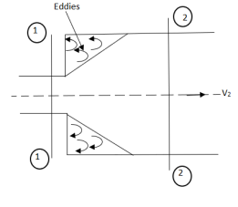
- Loss of head due to Sudden Enlargement.
- Consider a liquid flowing through a pipe which has sudden enlargement as shown in fig.
 =
= 
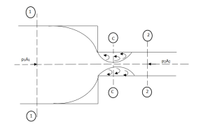
- Loss of head due to Sudden Contraction.
- Consider a liquid flowing in a pipe which has a Sudden Contraction in area as shown in fig.
 =
=  [
[  ]2
]2
- Loss of head at the entrance of a pipe:
- This is the loss of energy which occurs when a liquid enters a pipe which is connected to a large tank or reservoir.

- Loss of head at the exit of pipe:
- This is the loss of head due to the velocity of the liquid at the outlet of the pipe which is dissipated either in the form of a free jet or it is lost in the tank or reservoir.

- Loss of head due to an obstruction in a pipe:
- Whenever there is an obstruction in a pipe, the loss of energy takes place due to reduction of the area of the cross-section of the pipe at the place where obstruction is present.
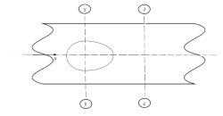
a = Maximum area of obstruction
A = Area of pipe
V = Velocity of liquid in pipe
 [
[  ]2
]2
- Loss of head due to bend in pipe:
- When there is any bend in a pipe, the velocity of the flow changes, due to which the separation of the flow from the boundary and also the formation of eddies takes place.


- Loss of head in various pipe fittings:
- The loss of head in various pipe fittings such as valves, couplings etc. is expressed as


Fig shows a horizontal pipe having steady flow.
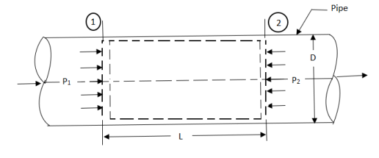
Consider control volume enclosed between section 1 and 2 of the pipe.
p1 = Intensity of pressure at section 1,
p2 = Intensity of pressure at section 2,
L = Length of the pipe , between section 1 and 2,
D = Diameter of the pipe,
f = Non-dimensional factor ( whose value depends on the material and nature of the pipe surface) , and
hf = Loss of head due to friction.
Propelling force on the following fluid between the two section is –
= (p1 – p2)A
(where , A = area of cross section of the pipe)
Frictional resistance force = f ’ PLV2
Where P = wetted perimeter, and
V = Average flow velocity.
Under Equilibrium condition,
Propelling force = Frictional resistance force
i.e. (p1 – p2) A = f PLV2.
Dividing both sides by weight density W, we have
( ) A =
) A =  PLV2
PLV2
hf =  LV2
LV2
hf = 
=  *
*  *
* 
The ratio  is called the hydraulic mean depth or hydraulic radius, denoted by m (or R).
The term ( ) has dimensions of hf and thus the term
  is a non-dimensional quantity and let us replace it by another constant f.
 ------- 1
In case of a circular pipe,
Hydraulic mean depth, 
Substituting this value in equation 1, we get
 ---------2
(The factor f is known as Darcy coefficient of friction.)
Equation 2 is known as Darcy-Weisbach equation.
Variation of friction factor f for laminar flow
The friction of factor f for laminar flow in pipes is given by

The equation shows that for laminar flow the friction factor f varies inversely with Re and it is independent of K/D ratio.
Variation of f for turbulent flow
For the fully developed turbulent flow, the friction factor f is a function of Re or K/D ratio or both, depending on whether the boundary is hydrodynamically smooth or rough or it is in transition.
- Equation
 has been plotted as shown in fig. Using log f and log Re as coordinates.
- On the same plot Nikuradse’s experimental data for smooth pipes also plotted.
- It is observed that the experimental points closely follow the trend of equation
 for Re varying from 4000 to 105
 - For Regreater than 105, there is an apparent deviation of the experimental points from the straight line represented by equation

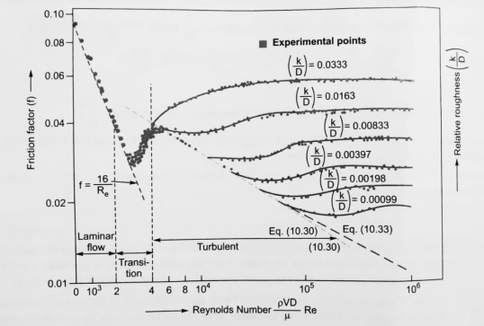
- Nikuradse shown by his experiment that for Re greater than 105 the values of frition factor given by equation
 were lower than the values of obtained experimentally.
 - The values of f for Re
 105 to Re = 4 × 10⁷obtained by using following equation.

- However, on basis of Nikuradse’s experiment data for turbulent flow in smooth pipes, it has been indicated that the experimental results, instead of following the trend of equation
 , follow closely the trend of equation
  which valid Re = 5×10⁴ to Re as high as 4 × 10⁷
 - The equation
 can be solved for f only by trial and error method. Therefore Nikuradse has given empirical relation f =
  which can be used directly to calculate value of f.
 - For turbulent flow in rough pipes, an expression for f is as

- But Nikuradse’s experimental results gave for rough pipes the following relation for f as

- When a fluid flows through a pipe, frictional resistance is offered to the motion of the fluid and the loss of head due to friction is expressed by Darcy- Weishach equation,

- But the loss of head can be predicted correctly only if the friction coefficient can be evaluated accurately.
- It can be shown by dimensional analysis that the friction coefficient depends upon the Reynolds number
 . And the ratio k/D
 - Thus,

Where, D = Diameter of the pipe
 = Density of the fluid.
 = Dynamic viscosity of the fluid.
K= average height of pipe wall roughness protrusions.
The term K / D is commonly known as relative roughness.
The equation 1 general equation which is applicable to laminar as well as turbulent flow in pipes.
Variation of friction coefficient f for smooth pipe-
- The coefficient of friction f for turbulent flow in both pipes is a function of Reynolds number only and is independent of relative roughness K / D.
- The value of f for smooth pipes for Re varying from 4000 to 105 is given by the following empirical relation.

- The values of f for Re
 105 to Re = 4 × 10⁷obtained by using following equation.

Nikuradse’s experimental result for turbulent flow in smooth pipeFor Re = 5×10⁴ to Re as high as 4 × 10⁷ for f is

f = 
Variation of friction coefficient f for rough pipes
- For turbulent flow in rough pipes, the friction coefficient f depends only on relative roughness (K/D) and is independent of Reynolds Number (Re). An expression for f is as follows:

- The experimental results obtained by Nikuradse follows the trend of following eqauion.

- Although Nikuradse’s experimental data on turbulent flow in smooth & artificially roughened pipe have been used to verify the various theoretically developed relationships turbulent pipe flow, yet NIkuradse’s experimental curves cannot be directly used to evaluate friction factor for commercial pipes.
- This is because the actual wall roughness pattern of commercial pipe is very much different from the uniform sand grain roughness used by Nikuradse.
- However, for commercial pipes it is possible to evaluate surface roughness of such pipes in terms of uniform sand grain diameter k, which is called equivalent sand grain roughness.
- In order to find the equivalent sand grain roughness k, for any commercial pipe, a series of experiment are conducted on the pipe at sufficiently large Reynold’s number & the limiting friction factor f is determined from Darcy Weisbach equation.
- This value of then substituted in equation
 & it is solved for R/K from which the value of equivalent sand grain roughness k for the pipe may be computed.
 - In the transitional region of boundary, the values of friction factor the artificially roughened pipes & commercial pipes are totally different.
- Colebrook and White developed an empirical equation of the following form to predict the friction factor for commercial pipes,

Where f1 (friction factor) = 4f (friction coefficient)
- We know, Friction factor for laminar region is governed by the formula;

- And for the turbulent region, it is governed by the Colebrook’s empirical relation;

- Based on the above two equations, following figure was prepared.
- It shows the functional dependence of friction factor (f) on Reynold’s no. (Re) and relative roughness (
 and is called as moody’s chart in honor of L.F. Moody who along with C.F. Colebrook, correlated the original data of Nikuradse in terms of relative roughness of commercially available pipes and prepared the chart.
 - Roughness values of some commercial pipes are shown on Moody’s chart.
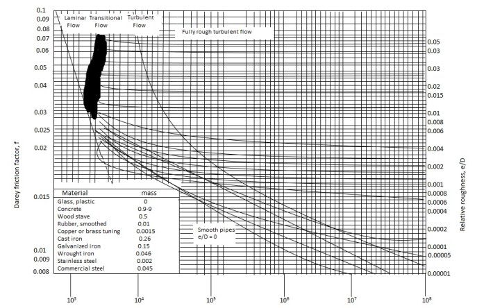
- But it should be kept in mind that these values are for new pipes, and the relative roughness of the pipes may increase with use as a result of corrosion and scale build up.
- Following observations can be made from Moody’s chart:
- For laminar flow, the fraction factor decreases with increase in Reynold’s Number, and it is independent of relative roughness.
- At very large Reynold’s Number, the friction factor curves corresponding to specified relative roughness are nearly horizontal, and thus the friction factors are independent of Reynold’s Number.
- For flow with moderate values of Re, the friction factor is indeed dependent on both the Reynold’s number as well as relative roughness and the value can be read from the chart.
- Note that even for smooth pipe (ε = 0); the friction factor is zero. That is, there is head loss in any pipe, no matter how smooth the surface is made. This is due to no slip condition at the pipe wall.
- This transition region from laminar to turbulent region (2300 < Re < 4000) is indicated on the chart. The flow in this region may be laminar or turbulent depending on the flow disturbances.
- It is probably one of the most widely accepted and used charts in engineering. Although it was developed for circular pipes, it can also be used foe non-circular pipes by replacing the diameter with hydraulic diameter.
- Also, the Moody’s chart involves various inherent inaccuracies and thus results obtained should not be treated as exact.
- It is usually considered to be accurate to ±15% over the entire range in the figure.
Pipes in series
- Pipes in series or compound pipes are defined as the pipes of different lengths and -different diameters connected end to end (in series) to form a pipe line as shown in fig.
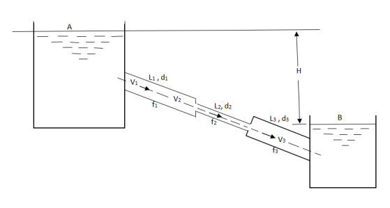
L1, L2,L3 = Length of pipes 1, 2 and 3 respectively
d1, d2, d3 = diameters of pipes 1, 2, 3 respectively
v1, v2, v3 = velocity of flow through pipes 1, 2, 3
f1, f2, f3 = coefficients of frictions for pipes 1, 2, 3
H = difference of water level in the two tanks
The discharge passing through each pipe is same


The difference in liquid surface levels is equal to the sum of the total head loss in the pipes.

If minor losses are neglected, then above equation becomes as

Pipe in parallel
- Consider a main pipe which divides into two or more branches as shown in fig. And again join together downstream to form a single pipe, then the branch pipes are said to be connected in parallel.
- The discharge through the main is increased by connecting pipes in parallel.
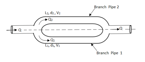
- The rate of flow in the main pipe is equal to the sum of rate of flow through branch pipes.

In this arrangement, the loss of head for each branch pipe is same.
Hence, Loss of head for branch pipe 1 = Loss of head of branch pipe 2

Equivalent pipe
- This is defined as the pipe of uniform diameter having loss of head and discharge equal to the loss of head and discharge of a compound pipe consisting of several pipes of different lengths and diameters.
- The uniform diameter of the equivalent pipe is called equivalent size of the pipe.
- The length of equivalent pipe is equal to sum of lengths of the compound pipe consisting of different pipes.
L1= length of pipe 1 and d1 = diameter of pipe 1
L2 = length of pipe 2 and d2 = diameter of pipe 2
L3 = length of pipe 3 and d3 = diameter of pipe 3
H = total head loss
L = length of equivalent pipe
d = diameter of equivalent pipe
Total head loss in the compound pipe, neglecting minor losses
 --------- 1
f1 = f2 = f3 = f


Substituting these values in equation 1, we have

 --------- 2
Head loss in the equivalent pipe, 
Where 
 --------- 3
Head loss in compound pipe and in equivalent pipe is same hence equating equations 2 and 3, we have

Or 
 --------- 4
Equation 4 is known as Dupuit equation
- When three or more reservoirs are connected by means of pipes having one or more junctions, the system is called branching pipe system.
- Figure shows three reservoirs at different levels connected to a single junction by means of pipes which are called branched pipes.
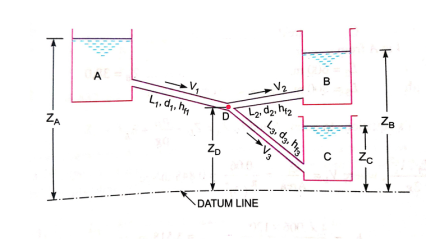
- The length, diameters and coefficient of friction of each pipes is given.
- It is required to find the discharge and direction of flow in each pipe.
- It is assumed that reservoirs are large and water levels in the reservoirs are constant so that steady conditions exist in the pipes.
- Also minor losses are assumed very small.
- The flow from is reservoir A takes place to junction D.
- The flow from junction D is towards reservoir C.
- Now the flow from junction D towards reservoir B will take place only when pizometric head (PD/W + ZD) is more than pizometric head at B.
- A pipe network is an interconnected system of pipes forming several loops of circuits.
- The pipe network is shown in figure.
- The examples of such networks of pipes are the municipal water distribution system in cities and laboratory supply system.
- In each system, it is required to determine the distribution of flow through the various pipes of the network.
The following are the necessary conditions for any network pipes:
1) The flow into each junction must be equal to the flow out of the junction. This is due to continuity equation.
2) The algebraic sum of head losses round each loop must be zero. This means that in each loop, the loss of head due to flow in clockwise direction must be equal to the loss of head due to flow in anticlockwise direction.
3) The head loss in each pipe is expressed as
The value of R depends upon the length of pipe, diameter of pipe and coefficient of friction of Pipe. The value of n for turbulent flow is 2.
We know that


Therefore, 
- This head loss will be positive when the pipe is a part of loop and the flow in the pipe is clockwise.
- Generally, the pipe network problems are difficult to solve analytically. Hence, the methods of successive approximation are used. Example Hardy cross method.
- A Syphon is a long bent pipe employed for carrying water from a reservoir at a higher elevation to another reservoir at a lower elevation when the reservoirs are separated by a hill or a high level ground in between as shown in fig.
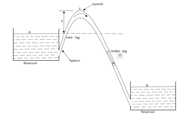
- The highest point (S) of the syphon is called the summit. The pressure at the point S is less than atmospheric pressure.
- The pressure at S can be reduced theoretically to -10.3 m of water but in actual practice this pressure is only -7.6 m of water.
- When the pressure at S becomes less than 2.7 m of water absolute, the dissolved air and the other gases would come out from water and collect at the summit.
- Therefore, syphon should be so laid that no section of the pipe will be more than 7.6 m above the hydraulic gradient at that section.
- Moreover, in order to limit the reduction of the pressure at the summit the length of the inlet-leg of the syphon is also required to be limited.
Numerical
Question : Determine the wall shearing stress in a pipe of diameter 100mm which carries water. The velocities are at the pipe centre and 30m from pipe centre are 2m/s and 1.5 m/s respectively. The flow in pipe is given as turbulent. Find  0.
0.
Soln. D = 0.1m R = D/2 = 0.05m
Umax = 1.5 m/s


Question : In a pipe of diameter 300 mm and Centre line velocity and velocity at a point 100mm from the centre line as measured by pitot tube are 2.4 m/s and 2 m / s respectively. Assume the flow in pipe to be turbulent, find i) discharge through the pipe
Ii) coefficient of friction
Iii) height of replenish projections.
Soln. D=0.3m R=D/2=0.15m Q=? f=? k=?
Umax = 2.4 m/s u=2m/s


u* = 0.146m/s

At y=R, u=umax

 log10 (1) = 0
 =1.85 m/s
Q=A× =
= 


f=0.0124


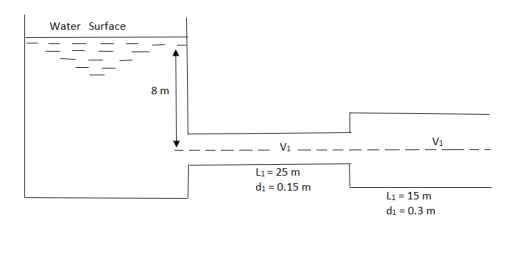
Question: A horizontal pipeline 40 m long is connected to a water tank at one end and discharges freely into the atmosphere to the other end. For first 25 m of its length from the tank, the pipe is 150 mm diameter and diameter is suddenly enlarges to 300 mm. The height of water level in the tank is 8 m above the centre of the pipe. Considering all losses. Find rate of flow. Take f = 0.01 for both pipes.
Given L = 40 m
L1 = 25 m
L2 = 15 m
d1 = 0.15 m
d2 = 0.3 m
H= 8 m
f = 0.01
A1 = 

By continuity equation
A1V1 = A2V2
V1 = 
Find Q.
Apply Bernoulli’s Theorem to the free surface of water in the tank and outlet of pipe


 -------- 1
Hf = Head loss of inlet + Major loss in pipe 1 + Head loss due to sudden enlargement + Major loss in pipe 2


Put in equation 1


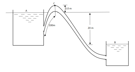
Question: A syphon of diameter 200 mm connects two reservoirs having a difference in elevation of 20 m. The length of syphon is 500 m and summit is 3 m above the water level in upper reservoir. The length of the pipe from upper reservoir to the summit is 100 m. Determine the discharge through the syphon. Neglect minor losses. Take f = 0.005 m.
Given
d = 0.2 m
H= 20 m
L = 500 m
h = 3 m
L1 = 100 m
f = 0.005
Find Q, 
Apply Bernoulli’s equation to point A and B


Apply Bernoulli’s equation to point A and C


Question: A syphon of diameter 200 mm connects two reservoirs having a difference of elevation of 15 m. The total length of the syphon is 600 m and summit is 4m above the water in the upper reservoir. If the separation takes place of 2.8 m water absolute, find max length of syphon from upper reservoir to the summit. Take f = 0.004 and atmospheric pressure = 10.3 m of water
Given
d = 0.2 m
H = 15 m
L = 600 m
h = 4 m


f = 0.004
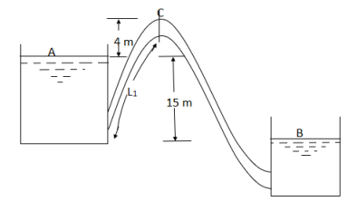
Apply Bernoulli’s equation to point A and B


Apply Bernoulli’s equation to point A and C


Question: Three pipes of 400 mm, 200 mm and 300 mm diameters have lengths of 400 m, 200 m and 300 m are connected in series to join two water tanks having level difference of 16 m. If coefficient of friction is same and equal to 0.005. Determine discharge first neglecting minor losses and the including them
Given
H = 16 m
L1 = 400 m
L2 = 200 m
L3 = 300 m
d1 = 0.4 m
d2 = 0.2 m
d3 = 0.3 m
f1 = f2 = f3 = 0.005


By continuity equation
A1V1 = A2V2
V2 = 


Now, Case 1: Neglecting minor losses


Case 2: Minor losses considered
H = Loss at entry + Major loss1 + Loss due to sudden contraction + Major loss 2 + Loss due to sudden enlargement + Major loss 3 + Loss at exit


Question : Three pipes of length 800 m, 500 m and 400 m and of diameters 500 mm, 400 mm, and 300 mm respectively are connected in series. These pipes are to be replaced by a single pipe of length 1700 mm. Find the diameter of the single pipe.
Given
L1 = 800 m
L2 = 500 m
L3 = 400 m
d1 = 0.5 m
d2 = 0.4 m
d3 = 0.3 m
L = 1700 m


Question: A pipeline 0.6 m diameter is 1.5 km long. To increase the discharge, another line of the same diameter is introduced parallel to the first in the second half of the length. Neglecting minor losses, find the increase in discharge if 4f = 0.04. Head at inlet is 300 mm.
D = 0.6 m
l = 1500 m
4f = 0.04
hf = 0.3 m
Case 1: Discharge through single pipe of length 1500 m


Case 2: When additional pipe of length 730 m and diameter 0.6 m connected in parallel with the last half length.
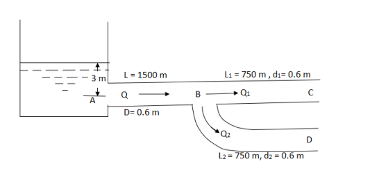
Let Q = Q1 + Q2
But length and diameter of each parallel pipe is same

Consider flow through pipe ABC

 -------- 1


Put in equation 1


Increase in discharge = Q – Q’


Question: An old water supply system pipe of 250 mm diameter of a city is to be replaced by two parallel pipes of smaller equal diameter having equal length and identical friction factor values. Find out new diameter required.
D= diameter of each parallel pipes = 0.25 m
Q = Discharge in old pipe
Q1 and Q2 = Discharge in first and second parallel pipe
Hf = hf1 = hf2
Q = Q1 + Q2
As diameter is same for both parallel pipes


But hf = hf1


Question: A 300 mm long pipe line is used for transmission of power. 130kW power is to be transmitted through the pipe in which water having a pressure of 40 bar at inlet is flowing. If pressure drop over the length of pipe is 500kN/m2 and f=0.024. Find i) Diameter of pipe ii) Efficiency of transmission.
Given
L = 3000 m
Power = 130 × 103 watts
P = 40 bar = 40 × 105 N/m2
Pressure drop = 800 kN/m2 = 800 × 103 N/m2
f = 0.024


Question : A farmer wishes to connect two pipes of different lengths and diameters to a common header supplied with 8 ×10⁻³m3/s of water from a pump. One pipe is 100 m long and 5 cm in diameter. The other pipe is 800m long. Determine the diameter of the second pipe such that both the pipes have same flow rate. Assume the pipes to be laid on level ground and coefficient of friction for both pipes as 0.02. Also determine the head loss in metres of water in the pipes.
Soln. Q= 8×10⁻³ m3/s
D1 = 0.05m
L1 = 100m
L2 = 800m
f = 0.02
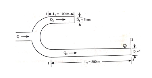


Where 

Similarly, for pipe 2


Reference:
Fluid mechanics – R.K. Rajput
Fluid mechanics & hydraulic machines. – R.K. Bansal
Hydraulics & fluid mechanics – P.N. Modi & S.M. Seth