Unit 6
Applications
(1) Hand level
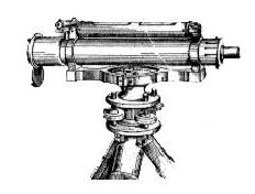
Hand Levels can be a great tool for use by professionals and consumers. They are a very practical and low-cost tool with a wide variety of uses.- They were first created when someone thought of attaching a spirit level to a telescope. Once the instrument is level, the user looks through the telescope to compare different points against the same reference point. It is used for rough levelling and not designed for precision work.
- Sometimes Professional Land Surveyors or Grading Contractors will use a Hand Level to get an idea or estimation of level instead of taking the time to set up a tripod with a levelling instrument.
- Engineer Supply sells Hand Levels. Internal stadia markings assist the user in determining the distances. Land Surveyors and Land Development Professionals use Hand Levels and Sight Levels as they are ideal for preliminary survey and simple distance estimation.
- Hand levels are ideal for laying lawns, paving, brick-laying, creating retaining walls, grading and excavation work, shed and pergola construction, fencing and numerous other home DIY projects.

(2) Abney level-
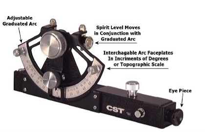
- An Abney Level is similar to a Hand Level in that it is a telescope with a spirit level attached. The main distinction is that the spirit level on an Abney level is not set in a static horizontal position.
- An Abney Level features a graduated arc. Engineer Supply sells Abney Levels. Once the arc is set at a specific degree it will cause the spirit level to show level at that specific angle.
- Many Abney levels will feature items such as stadia and will have a feature to focus items at different distances. Some even have a magnification feature. Abney levels are easier to use and inexpensive. They are used to measure degrees, percent of grade and topographic elevation.
- The user can then determine height, volume and grade through manipulating the readings with trigonometry.
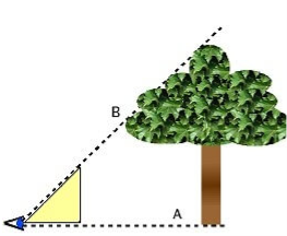
Land Surveyors, Builders, Contractors, Agriculture Professionals, Foresters, and many other Professionals use Abney levels. One unique use of an Abney level is to indirectly measure the height of a tree.

(3) Ghat Tracer-
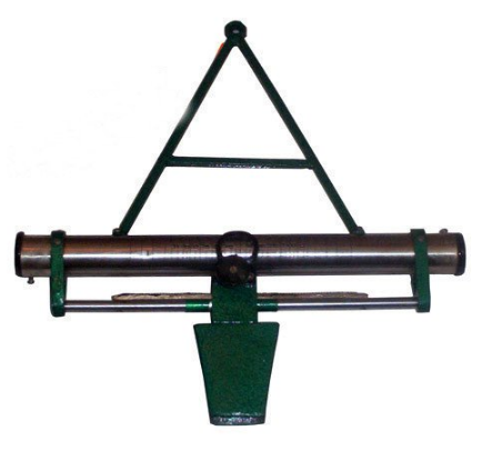
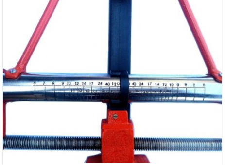
A reliable instrument for setting out a grade contour, i.e. locating points on a given gradient in the preliminary survey of a hill, road and also for measuring the angle of slope complete in wooden box with target and pole.
(4) Box Sextant-

Box sextant is a small pocket instrument which looks like a sextant enclosed in a box and is 75mm in diameter. Similar to the nautical instrument, it is also used for measuring both the horizontal and vertical angles. Box sextant is a very small and handy instrument which is easy to carry. It is also used in ships for celestial navigation, and it also works well even if the ship or boat is moving.
Uses of Box Sextant-
- Box sextant can be used as an optical square by setting Vernier to 90o.
- Box sextant can be used to measure angles in chain surveying.
- It is used to check the angles measured by other surveying instruments.
- Radiation in traversing can be done using box sextant.
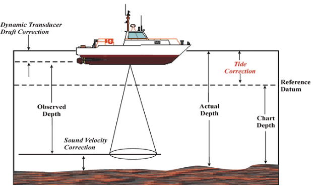
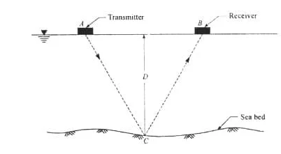
Hydrographic surveying or bathymetric surveying is the survey of physical features present underwater. It is the science of measuring all factors beneath water that affect all the marine activities like dredging, marine constructions, offshore drilling etc.
Hydrographic surveying is mainly conducted under authority concerns. It is mainly carried out by means of sensors, sounding or electronic sensor system for shallow water.
The information obtained from hydrographic surveying is required to bring up nautical charts which involves,
- Available depths
- Improved Channels
- Breakwaters
- Piers
- The aids to navigation harbor facility
These survey also take part in necessary data collection relating to construction and developments of port facilities, such as pier construction. This help in finding the loss in capacity due to silt and many uncertainties.
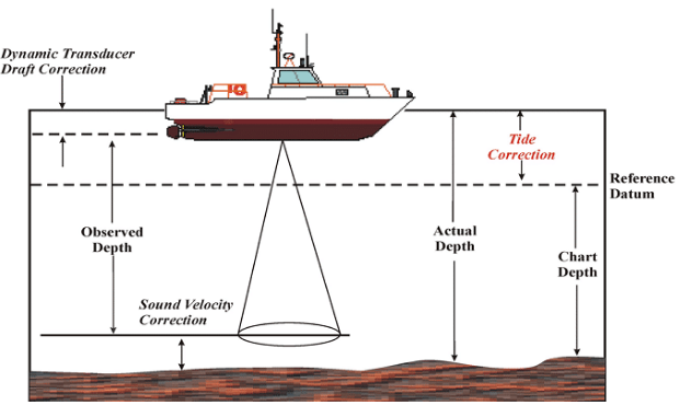
Applications of Hydrographic Surveying
Following are the applications of hydrographic surveying:
- Dock and Harbor Engineering
- Irrigation
- River Works
- Land reclamation
- Water Power
- Flood Control
- Sewage Disposal
Uses of Hydrographic Surveying
Uses of hydrographic surveying are given below:
- Depth of the bed can be determined
- Shore lines can be determined
- Navigation Chart Preparation
- Locate sewer fall by measuring direct currents
- Locating mean sea level
- Scouring, silting and irregularities of the bed can be identified
- Tide measurement
- River and stream discharge measurement
- Massive structures like bridges, dams’ harbors are planned
Preliminary Steps in Hydrographic Surveying
The method starts by locating special control points along the shore line. The sounding method is employed to determine the depth at various points by means of stationary boats. Sounding locations can be either made from boat to the control points or by fixing a point in the boat and taking sounding from the control point. Before this procedure certain preliminary steps have to be made:
- Reconnaissance
- Locate Horizontal Control
- Locate vertical Control
Reconnaissance
As every project require a start-up plan to complete it effectively and economically, reconnaissance has to be undergone. A complete reconnaissance of whole survey area to choose the best way of performing the survey.
This would facilitate satisfactory completion of the survey in accordance with the requirements and specifications governing such work. Aerial photographs would help this study.
Locating Horizontal Control
The horizontal control is necessary to locate all features of the land and marine in true relative positions. Hence a series of lines whose lengths and azimuths are determined by means of either triangulation or any other methods.
Tachometric and plane table survey can be conducted in order to undergo rough works. No rules are kept for establishing horizontal control as topography, vegetation, type, size of topography affect the rules.
But in general, a rule can be kept for type of control say:
- It is advisable to run traverses along each shore, connecting each other by frequent tie lines –If water body > 1km wide
- It is advisable to run transverse line only along one of the banks -If water body is narrow
- Triangulation system -If shorelines filled by vegetation
- Large network of triangulation system for large lakes and ocean shore lines
Locating Vertical Control
Before sounding establishment of vertical control is essential to determined. Numerous benchmarks are placed in order to serve as vertical control. Setting and checking the levels of the gauges are uses of benchmarks
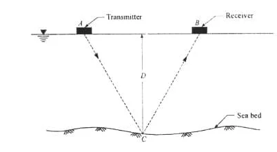
Tunnel surveying is a type of underground surveying for the construction of tunnels. Methods and procedure of tunnel surveying is discussed.
Special instructions on the type of survey and the equipment that must be used in the tunnel surveying procedure, for the tunnel construction are initially given by the planners.
The basic procedure of tunnel surveying is to align the center line in the ground and transfer that to the tunnel. This also involves leveling the surface on the ground and the internal of the tunnel.

Methods and Procedure of Tunnel Surveying
The steps that are involved in the tunnel surveying are detailed in the following points.
1. The initial procedure is to carry out a preliminary survey that is later made more precise by surveying the line on the surface of the area under consideration
2. From the start of the excavation, as a part of tunnel construction, it is essential to keep up even minute accuracy with the center line that is already marked. When a new area of excavation is commenced, the center line of the before finished work has to be carried forward over the new face. No shifting of the center line in vertical or horizontal direction is accepted, when the opposite faces meet with adjacent headings.
3. Ordinary engineers’ transit and properly handled works give satisfactory results for the construction of short tunnels.
4. Tunnel transit that is large and sophisticated, is fitted to a striding level, that helps in keeping the transverse axis horizontal. This is necessary for long tunnel construction.
5. The instruments above mentioned should undergo periodic maintenance, calibration as well as checking.
6. The procedure of levelling is carried out in a normal way. But areas with steep slopes are measured with utmost care. This is ensured by having equal values for backsight and foresight. This would reduce the errors that are caused by the human, like improper or mal -adjustments of the instruments.
7. There are two methods that can be employed to measure the horizontal distances. They are stepping and inclined sights. Any of these methods can be employed based on the area under consideration and convenience.
The steel tapes used for the measurement are checked for errors due to any cause of tension or temperature changes. This would result in cumulative errors in the measures.
The below figure shows the alignment of a curve line, based on which the construction must be proceeded (figure-1).
Fig.1: Alignment of Curve Line in Tunnel Surveying
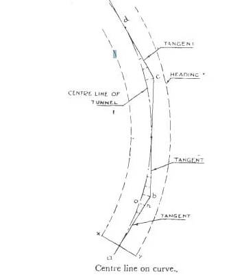
The center line of the curve in the figure is the alignment through which the center line of the tunnel must proceed. This is the curve that must be determined. The headings consist of short tangents that are drawn to the curved lines as ab, bc, cd etc. To locate the center line of the area, offsets from the above-mentioned tangents are set off.
When the heading has proceeded up to x y, point like ‘n’ on the tangents is aligned as shown in the figure. We then set off the calculated offset, i.e. n-o that will intersect the center line of the heading.
After each blasting of the heading face, the center line recommended being transferred.
How is Transferring of Center Line into the Tunnel Carried Out?
The transferring of the center line is a method that is done with great care, precision and accuracy. The accuracy throughout the execution of the same must be guided, else it can give up many related problems. Carelessness can cause the lines from opposite faces not to meet.
Even small deviation from the centerline can cause, over breaking. This whole undesirable work brings large expenditure than it has to be. The problem because more tiring when the procedure is undergone on hard rock strata. As shown in the figure, well elaborate equipment are made ready for the proceeding of the work.
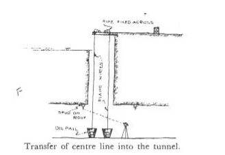
Fig.2: Arrangement in Transferring the Center Line Points to the Tunnel
Through the shaft constructed, the plumb bob weighing 22 lbs are taken down through the shaft, thus transferring the two center line points to the bottom as shown. It is carried out vertically downwards. The plumb bobs are suspended with the help of piano wires that are passing through the grooves, that is connected to a shaft for easily levelled movement of the plumb bob.
When the plumb bob reaches the bottom, they are replaced by heavy iron so that the weight will keep the wire straight. For higher precaution of the wire to resist any kind of vibration or oscillation, it can be immersed in a container of oil.
Once level, the line joining the two plumb bobs are extended with the help os a theodolite that is placed on the shaft floor, that is designated with respect to one point of the shaft roof, as shown in the figure.
A similar reference point is made to the opposite side of the roof, initially noted. Hence the center line is marked on the shaft floor and continued for further tunnel extension.
Decision of Shape and Size of the Tunnel
The shape of the tunnel is decided based on the nature and the type of the soil or the ground that is penetrated during the surveying and the excavation procedure. After surveying and related construction works, a choice of shape can be made. The size of the tunnel is already measured in the design, as it is based on the scope or requirement of the project.
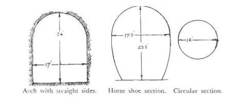
Among different cross sections, the circular cross sections are found to be the best shape to bring huge resistance towards the internal and external pressures. This also has another peculiarity of bringing larger size for a smaller diameter. But in engineers point of view, they demand high lining and covering to protect it from high vibration in railway uses.
So, an optimized shape is a tunnel with circular top and vertical side walls Another shape is the horseshoe type. They are compromised with the problems related to the circular tunnel shape.
Reference Books:
1. Principles of Surveying. Vol. I by J. G. Olliver, J. Clendinning - Van Nostrand
Reinhold.
2. Plane Surveying by A. M. Chandra, New Age International Publishers.
3. Surveying Vol. I & II by Dr. K. R. Arora, Standard Book House.
4. Plane surveying – David Clark.
Unit 6
Applications
(1) Hand level
Hand Levels can be a great tool for use by professionals and consumers. They are a very practical and low-cost tool with a wide variety of uses.- They were first created when someone thought of attaching a spirit level to a telescope. Once the instrument is level, the user looks through the telescope to compare different points against the same reference point. It is used for rough levelling and not designed for precision work.
- Sometimes Professional Land Surveyors or Grading Contractors will use a Hand Level to get an idea or estimation of level instead of taking the time to set up a tripod with a levelling instrument.
- Engineer Supply sells Hand Levels. Internal stadia markings assist the user in determining the distances. Land Surveyors and Land Development Professionals use Hand Levels and Sight Levels as they are ideal for preliminary survey and simple distance estimation.
- Hand levels are ideal for laying lawns, paving, brick-laying, creating retaining walls, grading and excavation work, shed and pergola construction, fencing and numerous other home DIY projects.

(2) Abney level-
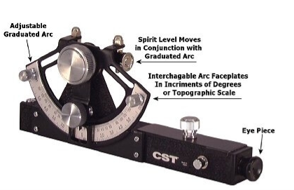
- An Abney Level is similar to a Hand Level in that it is a telescope with a spirit level attached. The main distinction is that the spirit level on an Abney level is not set in a static horizontal position.
- An Abney Level features a graduated arc. Engineer Supply sells Abney Levels. Once the arc is set at a specific degree it will cause the spirit level to show level at that specific angle.
- Many Abney levels will feature items such as stadia and will have a feature to focus items at different distances. Some even have a magnification feature. Abney levels are easier to use and inexpensive. They are used to measure degrees, percent of grade and topographic elevation.
- The user can then determine height, volume and grade through manipulating the readings with trigonometry.
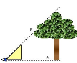
Land Surveyors, Builders, Contractors, Agriculture Professionals, Foresters, and many other Professionals use Abney levels. One unique use of an Abney level is to indirectly measure the height of a tree.
(3) Ghat Tracer-
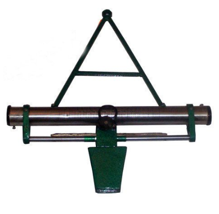
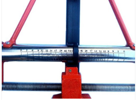
A reliable instrument for setting out a grade contour, i.e. locating points on a given gradient in the preliminary survey of a hill, road and also for measuring the angle of slope complete in wooden box with target and pole.
(4) Box Sextant-
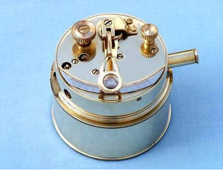
Box sextant is a small pocket instrument which looks like a sextant enclosed in a box and is 75mm in diameter. Similar to the nautical instrument, it is also used for measuring both the horizontal and vertical angles. Box sextant is a very small and handy instrument which is easy to carry. It is also used in ships for celestial navigation, and it also works well even if the ship or boat is moving.
Uses of Box Sextant-
- Box sextant can be used as an optical square by setting Vernier to 90o.
- Box sextant can be used to measure angles in chain surveying.
- It is used to check the angles measured by other surveying instruments.
- Radiation in traversing can be done using box sextant.
Hydrographic surveying or bathymetric surveying is the survey of physical features present underwater. It is the science of measuring all factors beneath water that affect all the marine activities like dredging, marine constructions, offshore drilling etc.
Hydrographic surveying is mainly conducted under authority concerns. It is mainly carried out by means of sensors, sounding or electronic sensor system for shallow water.
The information obtained from hydrographic surveying is required to bring up nautical charts which involves,
- Available depths
- Improved Channels
- Breakwaters
- Piers
- The aids to navigation harbor facility
These survey also take part in necessary data collection relating to construction and developments of port facilities, such as pier construction. This help in finding the loss in capacity due to silt and many uncertainties.
Applications of Hydrographic Surveying
Following are the applications of hydrographic surveying:
- Dock and Harbor Engineering
- Irrigation
- River Works
- Land reclamation
- Water Power
- Flood Control
- Sewage Disposal
Uses of Hydrographic Surveying
Uses of hydrographic surveying are given below:
- Depth of the bed can be determined
- Shore lines can be determined
- Navigation Chart Preparation
- Locate sewer fall by measuring direct currents
- Locating mean sea level
- Scouring, silting and irregularities of the bed can be identified
- Tide measurement
- River and stream discharge measurement
- Massive structures like bridges, dams’ harbors are planned
Preliminary Steps in Hydrographic Surveying
The method starts by locating special control points along the shore line. The sounding method is employed to determine the depth at various points by means of stationary boats. Sounding locations can be either made from boat to the control points or by fixing a point in the boat and taking sounding from the control point. Before this procedure certain preliminary steps have to be made:
- Reconnaissance
- Locate Horizontal Control
- Locate vertical Control
Reconnaissance
As every project require a start-up plan to complete it effectively and economically, reconnaissance has to be undergone. A complete reconnaissance of whole survey area to choose the best way of performing the survey.
This would facilitate satisfactory completion of the survey in accordance with the requirements and specifications governing such work. Aerial photographs would help this study.
Locating Horizontal Control
The horizontal control is necessary to locate all features of the land and marine in true relative positions. Hence a series of lines whose lengths and azimuths are determined by means of either triangulation or any other methods.
Tachometric and plane table survey can be conducted in order to undergo rough works. No rules are kept for establishing horizontal control as topography, vegetation, type, size of topography affect the rules.
But in general, a rule can be kept for type of control say:
- It is advisable to run traverses along each shore, connecting each other by frequent tie lines –If water body > 1km wide
- It is advisable to run transverse line only along one of the banks -If water body is narrow
- Triangulation system -If shorelines filled by vegetation
- Large network of triangulation system for large lakes and ocean shore lines
Locating Vertical Control
Before sounding establishment of vertical control is essential to determined. Numerous benchmarks are placed in order to serve as vertical control. Setting and checking the levels of the gauges are uses of benchmarks
Tunnel surveying is a type of underground surveying for the construction of tunnels. Methods and procedure of tunnel surveying is discussed.
Special instructions on the type of survey and the equipment that must be used in the tunnel surveying procedure, for the tunnel construction are initially given by the planners.
The basic procedure of tunnel surveying is to align the center line in the ground and transfer that to the tunnel. This also involves leveling the surface on the ground and the internal of the tunnel.

Methods and Procedure of Tunnel Surveying
The steps that are involved in the tunnel surveying are detailed in the following points.
1. The initial procedure is to carry out a preliminary survey that is later made more precise by surveying the line on the surface of the area under consideration
2. From the start of the excavation, as a part of tunnel construction, it is essential to keep up even minute accuracy with the center line that is already marked. When a new area of excavation is commenced, the center line of the before finished work has to be carried forward over the new face. No shifting of the center line in vertical or horizontal direction is accepted, when the opposite faces meet with adjacent headings.
3. Ordinary engineers’ transit and properly handled works give satisfactory results for the construction of short tunnels.
4. Tunnel transit that is large and sophisticated, is fitted to a striding level, that helps in keeping the transverse axis horizontal. This is necessary for long tunnel construction.
5. The instruments above mentioned should undergo periodic maintenance, calibration as well as checking.
6. The procedure of levelling is carried out in a normal way. But areas with steep slopes are measured with utmost care. This is ensured by having equal values for backsight and foresight. This would reduce the errors that are caused by the human, like improper or mal -adjustments of the instruments.
7. There are two methods that can be employed to measure the horizontal distances. They are stepping and inclined sights. Any of these methods can be employed based on the area under consideration and convenience.
The steel tapes used for the measurement are checked for errors due to any cause of tension or temperature changes. This would result in cumulative errors in the measures.
The below figure shows the alignment of a curve line, based on which the construction must be proceeded (figure-1).
Fig.1: Alignment of Curve Line in Tunnel Surveying
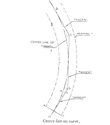
The center line of the curve in the figure is the alignment through which the center line of the tunnel must proceed. This is the curve that must be determined. The headings consist of short tangents that are drawn to the curved lines as ab, bc, cd etc. To locate the center line of the area, offsets from the above-mentioned tangents are set off.
When the heading has proceeded up to x y, point like ‘n’ on the tangents is aligned as shown in the figure. We then set off the calculated offset, i.e. n-o that will intersect the center line of the heading.
After each blasting of the heading face, the center line recommended being transferred.
How is Transferring of Center Line into the Tunnel Carried Out?
The transferring of the center line is a method that is done with great care, precision and accuracy. The accuracy throughout the execution of the same must be guided, else it can give up many related problems. Carelessness can cause the lines from opposite faces not to meet.
Even small deviation from the centerline can cause, over breaking. This whole undesirable work brings large expenditure than it has to be. The problem because more tiring when the procedure is undergone on hard rock strata. As shown in the figure, well elaborate equipment are made ready for the proceeding of the work.

Fig.2: Arrangement in Transferring the Center Line Points to the Tunnel
Through the shaft constructed, the plumb bob weighing 22 lbs are taken down through the shaft, thus transferring the two center line points to the bottom as shown. It is carried out vertically downwards. The plumb bobs are suspended with the help of piano wires that are passing through the grooves, that is connected to a shaft for easily levelled movement of the plumb bob.
When the plumb bob reaches the bottom, they are replaced by heavy iron so that the weight will keep the wire straight. For higher precaution of the wire to resist any kind of vibration or oscillation, it can be immersed in a container of oil.
Once level, the line joining the two plumb bobs are extended with the help os a theodolite that is placed on the shaft floor, that is designated with respect to one point of the shaft roof, as shown in the figure.
A similar reference point is made to the opposite side of the roof, initially noted. Hence the center line is marked on the shaft floor and continued for further tunnel extension.
Decision of Shape and Size of the Tunnel
The shape of the tunnel is decided based on the nature and the type of the soil or the ground that is penetrated during the surveying and the excavation procedure. After surveying and related construction works, a choice of shape can be made. The size of the tunnel is already measured in the design, as it is based on the scope or requirement of the project.
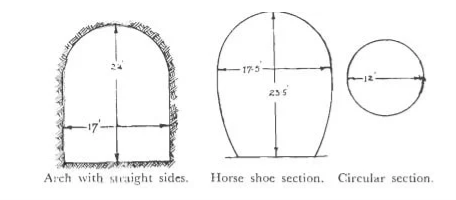
Among different cross sections, the circular cross sections are found to be the best shape to bring huge resistance towards the internal and external pressures. This also has another peculiarity of bringing larger size for a smaller diameter. But in engineers point of view, they demand high lining and covering to protect it from high vibration in railway uses.
So, an optimized shape is a tunnel with circular top and vertical side walls Another shape is the horseshoe type. They are compromised with the problems related to the circular tunnel shape.
Reference Books:
1. Principles of Surveying. Vol. I by J. G. Olliver, J. Clendinning - Van Nostrand
Reinhold.
2. Plane Surveying by A. M. Chandra, New Age International Publishers.
3. Surveying Vol. I & II by Dr. K. R. Arora, Standard Book House.
4. Plane surveying – David Clark.