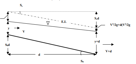
A steady non-uniform flow in a prismatic channel with gradual changes in its water surface elevation is named gradually-varied flow (GVF). The backwater produced by a dam or weir across a river and drawdown produced at a sudden drop in a channel is few typical examples of GVF. In a GVF, the velocity varies along the channel, and consequently, the bed slope, water surface slope, and energy line slope will all differ from each other. Regions of high curvature are excluded in the analysis of this flow.
The two basic assumptions involved in the analysis of GVF are
1. The pressure distribution at any section is assumed to be hydrostatic. This follows from the definition of the flow to have a gradually varied water surface. As gradual changes in the surface curvature give rise to negligible normal accelerations, the departure from the hydrostatic pressure distribution is negligible.
2. The resistance to flow at any depth is assumed to be given by the corresponding uniform flow equation, such as the Manning equation, with the condition that the slope term to be used in the equation is the energy line slope, Se and not the bed slope, S0. Thus, if in a GVF the depth of flow at any section is y, the energy line slope Se is given by,
|
(2.1)
where R = hydraulic radius of the section at depth y.
|
In open channel flow, specific energy (e) is the energy length, or head, relative to the channel bottom. Specific energy is expressed in terms of kinetic energy, and potential energy, and internal energy. The Bernoulli equation, which originates from a control volume analysis, is used to describe specific energy relationships in fluid dynamics. The form of Bernoulli’s equation discussed here assumes the flow is incompressible and steady.
The three energy components in Bernoulli's equation are elevation, pressure, and velocity. However, since with open channel flow, the water surface is open to the atmosphere, the pressure term between two points has the same value and is therefore ignored. Thus, if the specific energy and the velocity of the flow in the channel are known, the depth of flow can be determined. This relationship can be used to calculate changes in depth upstream or downstream of changes in the channel such as steps, constrictions, or control structures. It is also the fundamental relationship used in the standard step method to calculate how the depth of a flow changes over a reach from the energy gained or lost due to the slope of the channel.
With the pressure term neglected, energy exists in two forms, potential and kinetic. Assuming all the fluid particles are moving at the same velocity, the general expression for kinetic energy applies (KE = ½mv2). This general expression can be written in terms of kinetic energy per unit weight of the fluid,
(2.2)
Where: m= mass, v= Fluid velocity (length/time), V= Volume (length3), ρ= Fluid density (mass/volume), γ= Specific weight of water (weight/unit volume), g= Acceleration due to gravity (length/time2) The kinetic energy, in feet, is represented as the velocity head,
The fluid particles also have potential energy, which is associated with the fluid elevation above an arbitrary datum. For a fluid of weight (ρg) at a height y above the established datum, the potential energy is wy. Thus, the potential energy per unit weight of fluid can be expressed as simply the height above the datum, Combining the energy terms for kinetic and potential energies along with influences due to pressure and headloss results in the following equation: Where, y = the vertical distance from the datum (length), P = pressure (weight/volume), hf = headloss due to friction (length)
|
As the fluid moves downstream, energy is lost due to friction. These losses can be due to channel bed roughness, channel constrictions, and other flow structures. Energy loss due to friction is neglected in this analysis.
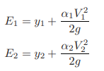
Equation 2.5 evaluates the flow at two locations: point 1 (upstream) and point 2 (downstream). As mentioned previously, the pressure at locations 1 and 2 both equal atmospheric pressure in open-channel flow, therefore the pressure terms cancel out. Head loss due to friction is also neglected when determining specific energy; therefore this term disappears as well. After these cancelations, the equation becomes,
and the total specific energy at any point in the system is,
|
Key Takeaways:
- A steady non-uniform flow in a prismatic channel with gradual changes in its water surface elevation is named gradually-varied flow (GVF). The backwater produced by a dam or weir across a river and drawdown produced at a sudden drop in a channel is few typical examples of GVF.
- The two basic assumptions involved in the analysis of GVF are:
- The pressure distribution at any section is assumed to be hydrostatic.
- In a GVF, the depth of flow at any section is y, the energy line slope Se is given by,
|
3. In open channel flow, specific energy (e) is the energy length, or head, relative to the channel bottom. Specific energy is expressed in terms of kinetic energy, and potential energy, and internal energy. The total specific energy at any point in the system is,
|
Volumetric discharge
To evaluate the kinetic-energy term, the fluid velocity is needed. The volumetric discharge, Q is typically used in open channel flow calculations. For rectangular channels, the unit discharge is also used, and many alternative formulas for rectangular channels use this term instead of v or Q. In US customary units, Q is in ft3/sec. and q is in ft2/sec.
q= Q/b (2.8)
where, q= unit discharge (length2/time),
Q = volumetric discharge (length3/time),
b = base width of the rectangular channel (length).
Equation 2.7 can then be rewritten for rectangular channels as,
|
(2.9)
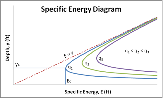
- The E-y diagram.
|
Fig. 2-2 Specific Energy Diagram
Three different q values are plotted on the specific energy diagram above. The unit discharges increase from left to right, meaning that q1 < q2 < q3. There is a distinct asymptotic relationship as the top part of the curve approaches the E = y line and the bottom part of the curve tends toward the x-axis. Also shown are the critical energy or minimum energy, Ec, and the corresponding critical depth value, yc. The values shown are for the q1 discharge only, but unique critical values exist for any discharge.
The critical depth value mentioned in the E–y diagram section above is mathematically represented by the ratio of the fluid velocity to the velocity of a small amplitude gravity wave. This ratio is called the Froude number.
|
(2.10)
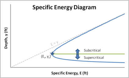
The critical depth has a Froude number equal to one and corresponds to the minimum energy a flow can possess for a given discharge. Not all flows are critical. Froude numbers below one are considered subcritical and Froude numbers above one are considered supercritical.
Fr=1; Critical (2.11)
Fr<1; Subcritical (2.12)
Fr>1; Supercritical (2.13)
Physically, subcritical flow is deep and the velocities are slow. This means subcritical flow has high potential energy and low kinetic energy. Supercritical flow on the other hand tends to be shallow and the velocities are fast. Supercritical flow has low potential energy and high kinetic energy.
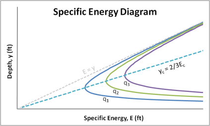
If we refer back to the E–y diagram in Fig. 2-2, it is seen that a line passes through the critical value on each successive discharge curve. This line corresponds to y=2/3E.
|
|
Fig.2-4
Depth values on the E–y curve greater than the critical depth correspond to subcritical flow depths. Likewise, values less than the critical depth correspond to supercritical flow depths.
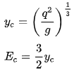
For rectangular channels, the critical depth can be calculated by taking the derivative of the energy equation and setting it equal to zero. The energy associated with the critical depth is found by placing the critical depth expression into the specific energy equation. The critical energy expression is demonstrated graphically by the line yc=2/3Ec, which connects critical depth values.
(2.14)
(2.15) (2.16)
|
|
Fig.2-5
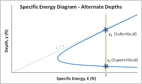
For a given energy value and discharge, there generally exist two possible corresponding flow depths. In the diagram above, the alternate depths are labeled y1 and y2 and correspond to the subcritical and supercritical flow regions, respectively. This holds for all energy values greater than critical energy. This relationship does not hold at critical energy where only the critical depth, yc, is possible and for energy values less than critical depth’s energy where there are no positive depths. The following equation can be used to solve for one alternate depth in terms of the other in rectangular channels. The values for y1 and y2 are interchangeable.
|
(2.17)
Theory and derivation of alternate depth relationship
In the open-channel flow of rectangular channels, the alternate depth equation relates the upstream(y1) and downstream(y2) steady-state flow depths of a flow that encounters a control device, such as a sluice gate, which conserves energy for a given discharge.
The alternate depth equation can be derived similarly to the conjugate depth equation. In the open-channel flow of rectangular channels, the conjugate depth equation relates the upstream(y1) and downstream(y2) steady-state flow depths for a flow that encounters a pure hydraulic jump, which conserves momentum for a given discharge. The mathematical derivation of the conjugate depth equation can be a useful tool in understanding the derivation of the alternate depth equation.
- Conjugate depth equation
|
(2.18)
Duality relationship between momentum and specific energy functions and the derivation of the alternate depth relationship
Another important concept that can be applied towards the derivation of the alternate depth equation arises from the comparison of the dimensionless momentum function to the dimensionless specific energy function. It can be seen that the dimensionless momentum function (M') has the identical functional relationship as the dimensionless specific energy function (E") when both are properly transformed. (Henderson 1966). From this comparison, it can be observed that any result that applies to the dimensionless momentum equation (M') would likewise apply to the dimensionless specific energy equation (E"). From this duality concept, we can determine the analog to the conjugate depth equation for the specific energy equation to provide an analytical relationship between alternate depths y1 and y2. Below gives the mathematical derivations behind this concept.
Dimensionless momentum function
1) Starting with the momentum function for a rectangular channel:
2) Divide through by (yc2 ) to obtain the dimensionless form:
(2.21)
|
Dimensionless specific-energy function
1) Starting with the specific-energy function for a rectangular channel: 2) Divide through by yc to obtain the dimensionless form:
3) Where E’=E/yc, y’=y/yc, and making the substitution for q2=gyc3
4) Setting yn=1/y’=yc/y and substituting into equation (2.23) we find the final dimensionless form of the specific-energy function:
(2.24) Through the comparison of the dimensionless momentum and specific-energy functions it can be observed that our final dimensionless specific-energy equation is identical to the functional relationship as was determined for the dimensionless-momentum equation:
|
Therefore, any result that applies to the dimensionless-momentum equation would likewise apply to the dimensionless specific-energy equation, provided the transform is used.
Derivation of alternate depth equation
Using the conjugate depth equation and the duality concept between the dimensionless forms of the momentum (M') and specific energy (E") functions an analytical relationship between alternate depths can be obtained.
1) Start with the conjugate depth equation (eq 2.18)
|
, where Fr1 is the Froude number at location 1
2) Develop the analog to Fr1 by observing that the dimensionless momentum equation (Eq. 2.21) has a value of y' equal to unity at critical depth. If we chose q= then the resulting M-y relationship will be numerically identical to the dimensionless M'-y' relationship since yc is unity. For this unit discharge q, the Froude number simplifies to:
|
(2.25)
3) Although dimensionally y1 and y1" are different, their numerical magnitudes are the same at unity and thus we can express the analog of the Fr1 in the conjugate depth equation as:
|
where the tilde in the Fˉr1 symbol indicates that this is simply the specific-energy equation analog to the Froude number in this analysis.
4) Substituting Fr1 into the dimensionless conjugate depth equation and recalling y”=1/y’= yc/y for both y1 and y2:
(2.27)
|
5) Observing that y2= yc/y2” and (y1”)3= (yc/y1)3=q2/gy13 , equation (2.27) can be simplified to the final analytical alternate depth relationship:
|
6) Recalling that for rectangular channels, yc=(q2/g)1/3 and Fr= v/ = q/y
= q/y and recognizing that Fr2= (yc/y)3= q2/gy3, the final analytical alternative depth relationship can also be represented as:
|
Notice that because of the symmetry of the original conjugate depth equation, the resulting dimensionless alternate depth equation applies regardless of the Froude number at location 1. That is, y1 may correspond to either supercritical or subcritical flow conditions. The alternate depth relationship will yield the alternate depth to y1 corresponding to the opposite flow regime in either case.
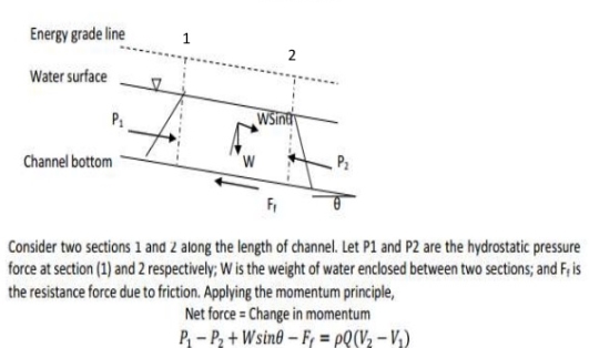
The momentum equation may be written as:
(2.29)
|
If one wishes to apply this equation to short sections of the channel such as a weir or hydraulic jump, the frictional resistance forces, Ffr can be neglected. With a flat channel of low slope, θ approaches 0, then the last two terms in equation 2.18 can be dropped. As a result, equation 2.18 becomes:
ρQ(β2V2- β1V1)= P1-P2 (2.30)
Assume also that the Boussinesq coefficient (β) is 1. From the fact that the pressure increases with depth to the maximum of ρgy at the channel bottom (y being depth, b being channel width, and ρ being fluid density), the overall pressure on the vertical flow area may be expressed as 1/2ρgby2. The velocities may be expressed as Q/A. For a rectangular channel:
(2.31)
For a channel section of any other shape, the resultant pressure may be taken at the centroid of the flow area, at a depth, z, from the surface. Then the momentum formulation is:
|
Either side of this equation is the definition of specific force, and the specific force is constant over a short stretch of the channel such as a hydraulic jump. The first term represents the change in momentum over time, and the second term the force of the water mass. As Chow (1959) explains, specific force is sometimes called force plus momentum or momentum flux.
|
Fig. 2-6 Momentum equation and Specific Force
Key Takeaways:
- For a given discharge, the specific energy can be calculated for various flow depths and plotted on an E–y diagram.
- The critical depth value represented by the ratio of the fluid velocity to the velocity of a small amplitude gravity wave is called the Froude number. Froude numbers below one are considered subcritical and Froude numbers above one are considered supercritical.
- The energy associated with the critical depth is found by
|
4. Alternate depths are calculated by using the formula
|
5. Specific force is the horizontal force of flowing water per unit weight of water. It is derived from the momentum equation
(PART B)
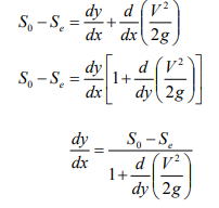
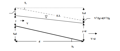
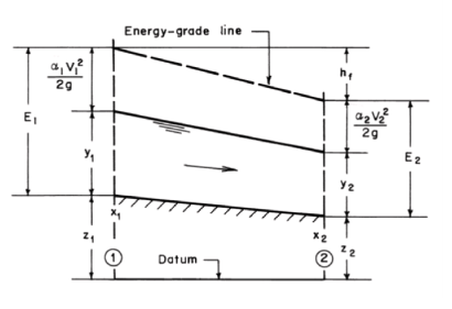
Since, S0 = Channel bed slope for uniform flow depth y, dy = Water depth variation for the dx canal reach, d (V2 /2g) = Velocity head variation for the dx reach. Writing the energy equation between the cross-sections 1 and 2 (Fig. 2-7.),
Fig. 2-7
Substituting this to Equ. (2.35),
(2.36)
|
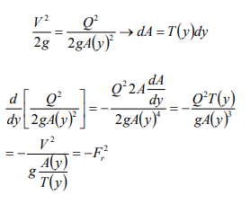
Equ. (2.36) is the general differential equation of the water surface profile for the gradually varied flows. dy/dx gives the variation of water depth along the channel in the flow direction.
- Classification of Flow Surface Profiles
1) y0 > yc ,
2) y0 < yc ,
3) y0 = yc . For horizontal (S0 = 0), and adverse slope ( S0 < 0) channels,
|
Horizontal channel, S0 = 0→ Q = 0,
The adverse channel, S0 < 0, Q cannot be computed,
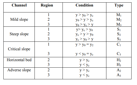
For horizontal and adverse slope channels, uniform flow depth y0 does not exist. Based on the information given above, the channels are classified into five categories as indicated in Table (2.1).
|
Table 2-1 Classification of channels
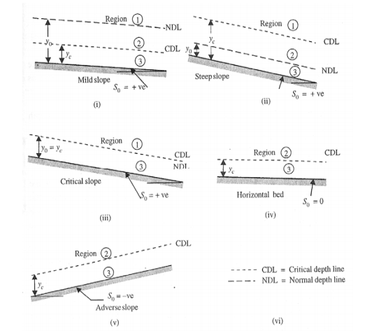
For each of the five categories of channels, lines representing the critical depth (yc) and normal depth (y0 ) (if it exists) can be drawn in the longitudinal section. These would divide the whole flow space into three regions:
Region 1: Space above the topmost line,
Region 2: Space between the top line and the next lower line,
Region 3: Space between the second line and the bed.
Figure (2.8) shows these regions in the various categories of channels.
|
Fig. 2-8 Regions of flow profiles
Depending upon the channel category and region of flow, the water surface profiles will have characteristic shapes. Whether a given GVF profile will have an increasing or decreasing water depth in the direction of flow will depend upon the term dy/dx in Equ. (2.36) being positive or negative
|
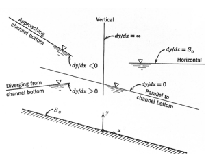
For a given Q, n, and S0 at a channel, y0 = Uniform flow depth, yc = Critical flow depth, y = Non-uniform flow depth. The depth y is measured vertically from the channel bottom, the slope of the water surface dy/dx is relative to this channel bottom. Fig. (2.9) is basic to the prediction of surface profiles from analysis of Equ. (2.36).
|
Fig. 2-9
To assist in the determination of flow profiles in various regions, the behavior of dy/dx at certain key depths is noted by studying Equ. (2.36) as follows:
And also,
1. As y → y0, V →V0, Se = S0
The water surface approaches the normal depth asymptotically 2. As y → yc, Fr 2 =1, 1 − Fr2 = 0,
3. As y → ∞ , V= 0→ Fr = 0→ Se→0
|
The water surface meets a very large depth as a horizontal asymptote. Based on this information, the various possible gradually varied flow profiles are grouped into twelve types (Table 2.2).
|
Table 2-2 Gradually Varied Flow profiles
- Examples
Example 2.1
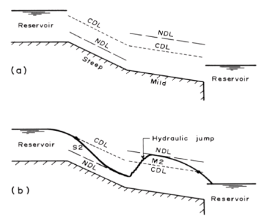
Sketch the water-surface profile in the channels connecting the reservoirs, as shown in Fig.2-10 a. The bottom slope of channel 1 is steep and that of channel 2 is mild.
|
Fig. 2-10
Solution:
Compute the critical and normal depths for each channel. Then plot the critical-depth line (marked as CDL in Fig. 2-10 b) and the normal-depth line (marked as NDL in Fig. 2.-10 b).
The water depth at the channel entrance is equal to the critical depth since the water level in the upstream reservoir is above the CDL of channel 1. Let us mark this water level at the channel entrance with a dot. The water level at the downstream end of channel 2 is lower than the CDL. Therefore, the water surface passes through the CDL approximately three to four times the critical depth upstream of the entrance to the downstream reservoir. Let us again mark this water level at the downstream end by a dot, as shown in Fig. 2-10 b.
In channel 1, the water surface at the entrance, after passing through the critical depth, tends to the normal depth. Thus, we have an S2 profile in channel 1. The flow decelerates downstream of the junction of channels 1 and 2 because of a mild slope. Hence, the flow depth increases until a hydraulic jump is formed. The water surface follows the M2 profile downstream of the jump and the exact location of the jump is determined by detailed calculations.
Example 2.2
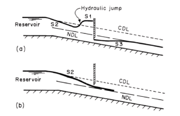
Sketch all possible water-surface profiles in the channel of Fig. 2-11. The channel is long and has a steep slope. Consider two different cases of the gate opening.
|
Fig.2-11
Solution:
Several different water surface profiles are possible depending upon the location of the control sections as well as the gate opening. We may divide these profiles into the following two categories:
a. Control at the channel entrance
b. Control at the gate
Let us consider each of these cases one by one. If the control is at the channel entrance, then the channel discharge is not controlled by the sluice gate. This is because we have supercritical flow in part of the channel length upstream of the sluice gate. Depending upon the gate opening, several different water-surface profiles are possible upstream of the gate, as shown in Fig. 2-11 a and 2-11 b. The flow depth approaches the NDL
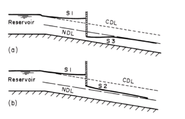
asymptotically since the channel is long. Depending upon the gate opening, S1, S2, or S3 profiles are possible, as shown in Fig. 2-11. The sluice gate controls the channel discharge only if the backwater from the gate extends to the channel entrance. In such a case, we have an S1 profile upstream of the gate in all cases (Fig. 2-11). However, downstream of the gate, the type of the surface profile depends on the gate opening, as shown in Fig. 2-12. In this figure, a small drop in the water level at the channel entrance is shown to account for the entrance losses and the velocity head.
|
Fig 2-12
Referring to Fig. 2-13, let us say that we know the flow depth at section 1 and we want to determine the location of section 2, where a specified flow depth, y2 will occur in a given channel for a specified discharge, Q.
In other words, the statement of our problem is as follows: The flow depth, y1, at distance x1 (i.e. section 1 in Fig. 2-13) is known; determine distance x2 where a specified flow depth y2 will occur. The properties of the channel section, So, Q, and n are known. If So = slope of the channel bottom, then referring to Fig. 2-13,
z2 = z1 − So(x2 − x1) (2.37)
Also, the specific energy
|
The slope of the energy grade line (For simplicity we will refer to it as the friction slope) in gradually varied flow may be computed with a negligible error by using the corresponding formulas for friction slopes in the uniform flow [Chow, 1959; Henderson, 1966]. However, since the flow depth, y varies with distance, x, the friction slope Sf is a function of x as well. The following approximations have been used [U.S. Army Corps of Engineers, 1982] to select a representative value of Sf for the channel length between Sections 1 and 2:
|
Fig.2-13 Computation of distance for specified depth
Average friction slope
Geometric mean friction slope
Harmonic mean friction slope
|
By expanding the right-hand side of the above approximations in a Taylor series, we can prove that these three formulations for the approximation of the friction slope give identical results if the terms of the order (ΔSf /Sf1)2 and higher are neglected. In this expression, ΔSf = Sf2 − Sf1. Laurenson [1986] showed that the average slope (Eq. 2.39a) gives the lowest maximum error although it is not always the smallest error. If the distance between sections 1 and 2 is short or the flow depths y1 and y2 are not significantly different, then Eq. 2.39a yields satisfactory results, in addition to being the simplest of the three approximations. Therefore, its use is recommended. Hence, an expression for hf may be written as
Yields
(2.41)
By substituting the expression for z2 from Eq. 2.37 into Eq. 2.41, and canceling out z1, we obtain
This equation may be written as
|
Now, the location of section 2 is known. This is the starting value for the next step. Then, by successively increasing or decreasing the flow depth and determining where these depths will occur, the water-surface profile in the desired channel length may be computed. In Eq. 2.43, the direction of computations is automatically taken care of if the proper sign for the numerator and the denominator is used. Note that both the numerator and the denominator are very small and extreme care should be exercised in using the proper number of significant digits in the computations and rounding off the values.
There are two, main disadvantages of this method.
(1) The flow depth is not computed at the predetermined locations. Therefore, interpolations may become necessary if the flow depths are required at specified locations. Similarly, the cross-sectional information has to be estimated if such information is available only at the given locations. This may not yield accurate results in addition to requiring additional effort.
(2) It is cumbersome to apply to nonprismatic channels.
Key Takeaways:
- dy/dx gives the variation of water depth along the channel in the flow direction.
|
2. Channels can be categorized into five sections: Mild slope, Steep slope, Critical slope, Horizontal bed, Adverse slope. Depending upon the channel category and region of flow, the water surface profiles will have characteristic shapes.
References:
1. Fluid Mechanics – Streeter-McGraw-Hill International Book Co., Auckland.
2. Flow in open channel – V. T. Chaw - McGraw-Hill International Book Co., Auckland.
3. Fluid Mechanics – K. L. Kumar – Eurasia Publication House, Delhi.

