UNIT-5
IMPACT OF JET
Water turbines are widely used throughout the world to generate power. In the type of water turbine referred to as a Pelton wheel, one or more water jets are directed tangentially onto vanes or buckets that are fastened to the rim of the turbine disc. The impact of the water on the vanes generates a torque on the wheel, causing it to rotate and to develop power. Although the concept is essentially simple, such turbines can generate considerable output at high efficiency. Powers over 100 MW, and hydraulic efficiencies greater than 95%, are not uncommon. It may be noted that the Pelton wheel is best suited to conditions where the available head of water is great, and the flow rate is comparatively small. For example, with a head of 100 m and a flow rate of 1 m3 /s, a Pelton wheel running at some 250 revs/min could be used to develop about 900 kW. The same water power would be available if the head were only 10 m and the flow was 10m3 /s, but a different type of turbine would then be needed.
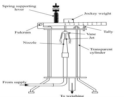
To predict the output of a Pelton wheel, and to determine its optimum rotational speed, we need to understand how the deflection of the jet generates a force on the buckets, and how the force is related to the rate of momentum flow in the jet. In this experiment, we measure the force generated by a jet of water striking a flat plate or a hemispherical cup and compare the results with the computed momentum flow rate in the jet.
|
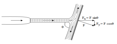
Fig. 5-1 Impact of jet
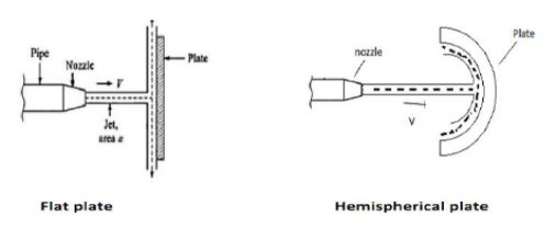
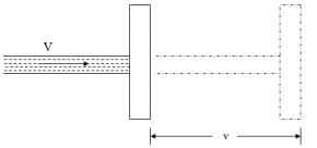
The jet of water is directed to hit the vanes of a particular shape a force is exerted on the vane by the jet. The amount of force depends on the diameter of the jet shape and the fluid flow rate it also depends on whether the vane is moving or stationary.
|
Fig. 5-2
Impact of jet
The liquid comes out in the form of a jet from the outlet of a nozzle which is fitted to a pipe through which the liquid is flowing under pressure. A jet is a stream of fluid that is projected into a surrounding medium, usually from some kind of a nozzle, aperture, or orifice. Jets can travel long distances without dissipating. Jet fluid has higher momentum compared to the surrounding fluid medium. In the case that the surrounding medium is assumed to be made up of the same fluid as the jet, and this fluid has a viscosity, the surrounding fluid is carried along with the jet in a process called entrainment.
The impulse-momentum equation for fluid flow can be derived from the well-known Newton’s second law of motion. The resultant force Fˉ acting on a mass particle m is equal to the time rate of change of linear momentum of the particle:
Fˉ= d(mVˉ)/dt
This law applies equally well to a system of mass particles. The internal forces between any two mass particles of the system exist in pairs. They are both equal and opposite of each other and, therefore, will cancel out as outlined in Newton’s third law of motion. The external forces acting on mass particles of the system can then be summed up and equated to the time of change of the linear momentum of the whole system,
If we define momentum by I˘=mVˉ, then
|
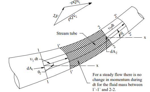
Extending Newton’s second law of motion to fluid flow problem, take as a free body the fluid mass included between sections 1-1 and 2-2 within a length of a flow channel (Fig. 5-3).
|
Fig. 5-3
The fluid mass of the free body 1-1 and 2-2 at time t1 moves to a new position 1’-1’ and 2’-2’ at time t2 when t2-t1 equals dt. Sections 1’-1’ and 2’-2’ are curved because the velocities of flow at these sections are non-uniform. It should be noted that, for a steady flow, the following continuity equation holds.
[Fluid mass within section 1-1 and 1’-1’] = [Fluid mass within section 2-2 and 2’-2’] M (11′1′1) = M ( 22′2′2 ) The momentum of the system at time t,
The momentum of the system at time t+dt,
Change of momentum at dt time,
Furthermore, when the flow is steady,
From Eqs. (5.3) and (5.4),
From Eqs. (5.2) and (5.6),
|
This equation is known as the impulse-momentum equation.
Key Takeaways:
|
The following cases of the impact of a jet, i.e. the force exerted by the jet on a plate will be considered:‐
1. Force exerted by the jet on a stationary plate
a) Plate is vertical to the jet
b) Plate is inclined to the jet
c) Plate is curved
2. Force exerted by the jet on a moving plate
a) Plate is vertical to the jet
b) Plate is inclined to the jet
c) Plate is curved
Force exerted by the jet on a stationary vertical plate
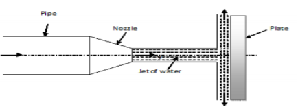
Consider a jet of water coming out from the nozzle strikes the vertical plate
|
Fig 5-4
V = velocity of jet, d = diameter of the jet, a = area of x – section of the jet.
The force exerted by the jet on the plate in the direction of the jet.
Fx = Rate of change of momentum in the direction of the force.
Rate of change of momentum in the direction of force = initial momentum – final momentum/time
= mass x initial velocity – mass x final velocity / time
= mass/time (initial velocity – final velocity)
= mass/ sec x (velocity of the jet before striking mass/ sec x (velocity of the jet before striking – final velocity of jet after striking)
Force of Jet Impinging On An Inclined Fixed Plate:
Consider a jet of water impinging normally on a fixed plate as shown in fig.5-5
|
Fig. 5-5
Let, • Ɵ = Angle at which the plate is inclined with the jet Force exerted by the jet on the plane = waV2/g KN Force exerted by the jet in a direction normal to the plate, F= waV2sin Ɵ/g and the force exerted by the jet in the direction of flow,
Similarly, the force exerted by the jet in a direction normal to flow,
|
Force Of Jet Impinging On A Moving Plate:
|
Fig. 5-6 Jet impinging on a moving plate
Let, v= Velocity of the plate, as a result of the impact of jet A little conversation will show that the relative velocity of the jet concerning the plate equal to (V-v) m/s. For analysis purposes, it will be assumed that the plate is fixed and the jet is moving with a velocity of (V-v) m/s. Therefore force exerted by the jet,
Force Of Jet Impinging On A Moving Curved Vane:
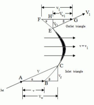
Consider a jet of water entering and leaving a moving curved vane as shown in fig.5-7
|
Fig. 5-7 Jet impinging on moving curved vane
Consider a curved vane moving with a velocity v under the action of the dynamic thrust exerted by a jet of water gliding over it.
Let V be the velocity of the jet at the inlet.
Let Vr be the relative velocity of the jet for the vane.
The shape of the vane and its position for the jet is so designed that the jet should just glide over it so that there will be no loss of energy due to shock. For this condition, the direction of the relative velocity Vr at the inlet should be along the tangent to the vane at the inlet.
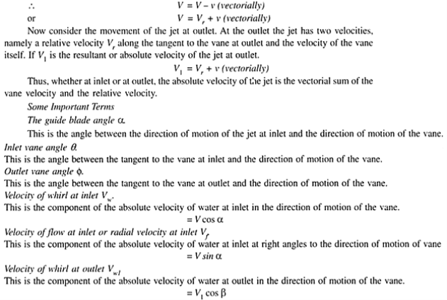
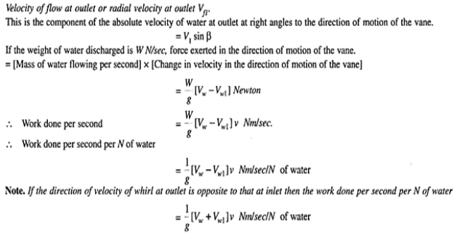
The relative velocity at the inlet is the vectorial difference between the velocity of the jet and the velocity of the vane at the inlet.
|
Key Takeaways:
- Force exerted by the jet on a stationary vertical plate
= mass/ sec x (velocity of the jet before striking mass/ sec x (velocity of the jet before striking – final velocity of jet after striking)
2. Force of Jet Impinging On An Inclined Fixed Plate is given by:
|
3. Force Of Jet Impinging On A Moving Plate is given by:
|
4. The work done by the force of jet impinging on a moving curved vane is given by:
|
In turbomachinery, a velocity triangle or a velocity diagram is a triangle representing the various components of velocities of the working fluid in a turbomachine. Velocity triangles may be drawn for both the inlet and outlet sections of any turbomachine. The vector nature of velocity is utilized in the triangles, and the most basic form of a velocity triangle consists of the tangential velocity, the absolute velocity, and the relative velocity of the fluid making up three sides of the triangle.
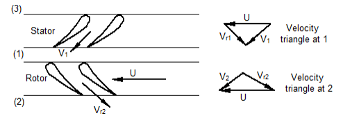
Consider turbomachine consisting of a stator and a rotor. The three points that are very much important to draw the velocity triangles are entry to the stator, the gap between the stator and rotor, and exit from the rotor. These points are labeled 3, 1, and 2 respectively in figure 3.2, and a combination of rotor and stator is called stage in turbomachines. The fluid enters the stator at point 3 but as the stator is not moving there is no relative motion between the incoming flow and the stator so there is no velocity triangle to draw at this point. At point 1 the flow leaves the stator and enters the rotor. Here there are two flow velocities, the absolute velocity of the flow (V) viewed from the point of view of the stationary stator and relative velocity of flow (Vr) viewed from the point of view of the moving rotor. The rotor is moving with a tangential velocity of magnitude U. At point 2 the flow leaves the rotor and exits the stage. Again there are two flow velocities, one by viewing from the moving rotor and another by viewing from outside the rotor where there is no motion.
|
Fig. 5-7 Velocity triangles for a turbomachine
Therefore velocity triangles can be drawn for the point 1 and point 2 as shown in figure 5-7, the methodology for this is as follows:
1. Draw the flow that is known
2. Draw the blade speed
3. Close the triangle with the remaining vector
4. Check that the key rule applies: 
The velocity triangles at the inlet and outlet of the rotor are of utmost importance in deciding the size of the turbomachine for the given power output.
Key Takeaways:
- In turbomachinery, a velocity triangle or a velocity diagram is a triangle representing the various components of velocities of the working fluid in a turbomachine. Velocity triangles may be drawn for both the inlet and outlet sections of any turbomachine.
- The methodology for this is as follows includes drawing the flow that is known, drawing the blade speed, Closing the triangle with the remaining vector, Checking that the key rule applies:

Example
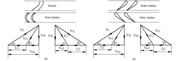
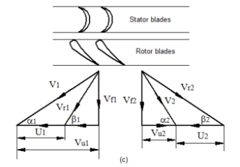
1. Sketch velocity diagrams for R=0, R=0.5, and R=1 and label.
A: For impulse axial flow turbine, R=0, thus Vr1 should be equal to Vr2, and if the blades are equiangular then, β1=β2, as shown in figure 5-8, (a). Here energy transfer is purely due to a change in dynamic pressure.
|
Fig. 5-8 Velocity triangles for axial flow turbine R=0, R=0.5, and R=1
For 50% reaction axial flow turbine, R=0.5, thus and if the stator and rotor blades are symmetric (two blades are identical but orientations are different) then, α1=β2 and α2=β1 and also V1=Vr2 and V2=Vr1 as shown in figure 5-8 (b). Here energy transfer due to change in dynamic pressure is equal to energy transfer due to change in static pressure. For a fully (100%) reaction axial flow turbine, R=1, thus V1 should be equal to V2 and also α1=α2 as shown in figure 5-8 (c). Here stator acts purely as a directional device and doesn't take part in the energy conversion process. The rotor acts both as the nozzle and as the energy transfer device, so energy transfer is purely due to a change in static pressure.
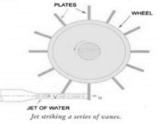
Impact of Jet on series of flat plates Mounted on a wheel
The configuration of the system is shown in fig, 5-9. In this case, the plate fixed on the wheel moves with a velocity u in the direction of the jet. As one plate comes out of the jet, the jet strikes on the other plate, and the whole flow from the jet strikes the plate when all plates are considered.
|
Fig. 5-9 Jet striking series of vanes
The velocity of the jet with which jet strikes the plate is the relative velocity of the jet which is (V-u) The final velocity of the jet after striking the plate = V-u =0. Change in velocity = initial relative velocity – Final relative velocity = (V-u) – 0= V-u Force acting on the plate = 𝑚̇ 𝑥 𝐶ℎ𝑎𝑛𝑔𝑒̇ 𝑖𝑛 𝑣𝑒𝑙𝑜𝑐𝑖𝑡𝑦 = 𝜌𝑎𝑉(𝑉 − 𝑢) Newtons The efficiency of the system is given by 𝜂 = 𝑂𝑢𝑡𝑝𝑢𝑡 /𝐼𝑛𝑝𝑢𝑡 = 𝐹 𝑥 𝑢 /(1/2)𝑚𝑉2 = 𝜌𝑎𝑉(𝑉−𝑢)𝑢 /(1/2) 𝜌𝑎𝑉𝑉2 𝜂 = 2(𝑉−𝑢)𝑢 /𝑉2 For finding out the maximum velocity for the given input (V is constant), The condition required is, 𝑑𝜂/𝑑𝑢 = 0 𝑑/𝑑𝑢 [𝑢(𝑉 − 𝑢)] = 0 V- 2u = 0 u = 𝑉/2 Corresponding maximum efficiency is given by 𝜂𝑚𝑎𝑥 = 2 (2𝑢−𝑢)𝑥 𝑢 /(2𝑉)2 = 0.5 𝜂𝑚𝑎𝑥 = 50%
|
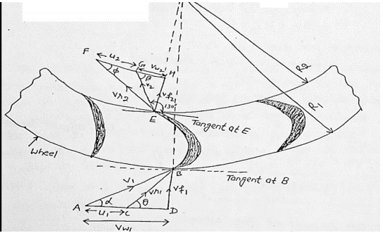
Force exerted on series of radial curved vanes:
Consider a series of radial curved vanes mounted on a wheel as shown in fig 5-10. The jet water impinges on the vane and the wheel starts rotating at a speed
|
Fig. 5-10. Force exerted on series of radial curved vane
Let, 𝜔 = angular speed of the wheel R1, R2 = Radii of the wheel at inlet and outlet of vane respectively As vane are situated radially around the wheel blade velocities at inlet and outlet tip of vane would be different u1 = 𝜔 R1 and u2 = 𝜔 R2 The flow system is inward or outward depending upon whether the jet enters the outer periphery or the inner periphery. The mass of water striking/sec = mass of water issuing from the nozzle per second = 𝜌aV1 The momentum of water striking the vanes (in tangential direction) per second at the inlet = 𝜌aV1 x Vw1 Similarly Momentum of water striking the vanes (in tangential direction) per second at the outlet = 𝜌aV1 x (- Vw2) = - 𝜌aV1 x Vw2 -ve sign is taken as V2 at the outlet is in opposite direction. Now, angular momentum per second at inlet = momentum at inlet x radius at inlet = 𝜌aV1 x Vw1 x R1 angular momentum per second at outlet = 𝜌aV1 x Vw2 x R2
Torque exerted by water on the wheel, T = rate of change of angular momentum = (initial angular momentum/sec - final angular momentum/sec) = 𝜌aV1 x Vw1 x R1 – (-𝜌aV1 x Vw2 x R2) = 𝜌aV1 (Vw1 x R1 + Vw2 x R2) W.D./sec on the wheel = T x 𝜔 = 𝜌aV1 (Vw1 x R1 + Vw2 x R2) x 𝜔 = 𝜌aV1 (Vw1 x 𝜔 R1 + Vw2 x 𝜔 R2) = 𝜌aV1 (Vw1 x u1 + Vw2 x u2) In case β is an obtuse angle, then W.D./sec = 𝜌aV1 (Vw1 x u1 - Vw2 x u2) If discharge is radial at outlet, then β = 900 W.D./sec = 𝜌aV1 (Vw1 x u1) (Vw2 = 0) Efficiency of radial curved vane η = 𝑊.𝐷./ 𝑠𝑒𝑐 𝐾.𝐸./𝑠𝑒𝑐 = 𝜌aV1 (Vw1 x u1 ± Vw2 x u2)/ 𝟏/𝟐 𝜌aV3 = 2 (Vw1 x u1 ± Vw2 x u2) 𝑉2
|
References:
1. Fluid Mechanics – Streeter-McGraw-Hill International Book Co., Auckland.
2. Flow in open channel – V. T. Chaw - McGraw-Hill International Book Co., Auckland.
3. Fluid Mechanics – K. L. Kumar – Eurasia Publication House, Delhi.
