UNIT-6
PUMPS AND TURBINES
(PART A)
A hydraulic turbine is a prime mover that converts a substantial part of the potential and kinetic energy of flowing water to mechanical energy. Water stored in high-level reservoirs like dams has enormous potential energy. This water having high energy is brought down the penstock pipes and directed to run the turbines.
The mechanical energy of the turbines can be converted into electrical energy by generators that are directly coupled to the turbine shaft. Hydroelectric power constitutes the major part of the total power developed from all sources. Power developed from oil, coal, and such sources is insignificantly small compared to hydroelectric power.
Hydroelectric Plant:
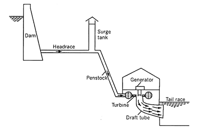
A hydroelectric plant has the following units:
(a) A dam to store water at a high level creating a reservoir.
(b) Head race system providing the means to convey the water from the reservoir to the powerhouse, using large-diameter pipes or tunnels.
(c) A surge tank to protect the pipeline from bursting due to sudden changes in the discharge rate.
(d) Penstock pipes which are pressure pipes laid at a steep slope.
(e) Powerhouse where the turbine and generator are installed.
(f) Tailrace to carry the water discharged by the turbine. This is usually in the form of channels.
Hydroelectric power production is of great advantage compared with other methods of power generation. Hydroelectric plants involve relatively simple construction needing lesser maintenance. These units automatically respond and adjust to changing loads. The water discharged finally by the turbines can be utilized for irrigation.
There are however shortcomings like scanty rainfall disturbing power supply, the high initial cost of various civil engineering works, and the high cost of transmission lines.
Fig. 6-1 shows a layout of a hydroelectric power plant.
|
Fig. 6-1 Layout of a hydroelectric powerplant
A hydraulic turbine consists of
(i) a wheel called the runner provided with several curved vanes on its periphery,
(ii) a guiding apparatus to direct the flow of water at the inlet in the specified direction.
A turbine needs a source of water supply say a reservoir from which the water is drawn by pipes.
Turbines may be classified in two ways, viz.
(a) based on the nature of the energy head of water at inlet, and
(b) based on the direction of flow along the vanes.
(a) Classification of Turbines Based on the Nature of Energy Head Possessed by Water at Inlet:
Turbines may be classified into Reaction or pressure turbines and Impulse or velocity turbines.
(i) Reaction or Pressure Turbine:
A reaction turbine is a turbine in which the water entering the runner possesses pressure as well as kinetic energy. This type of turbine is always enclosed by a casing.
(ii) Impulse or Velocity Turbines:
An impulse turbine is a turbine in which the water entering the runner possesses kinetic energy only, i.e., in this case, the water is throughout at atmospheric pressure.
Examples:
(i) Reaction turbines – Francis turbine, Kaplan turbine, Thomson turbine, Scotch turbine, or Barker’s mill.
(ii) Impulse turbines – Pelton wheel, Turgo wheel, Jonval turbine, Girard turbine.
(b) Classification of Turbines Based on the Direction of Flow of Water:
In a radial flow turbine, the water moves along the vanes towards the axis of rotation of the runner or away from it. When the flow is towards the axis of rotation, the turbine is called an inward flow turbine. When the flow is away from the axis of rotation of the turbine is called an outward flow turbine.
When the water flows parallel to the axis of rotation, the turbine is called an axial or parallel flow turbine.
In a mixed flow turbine, the water enters radially inwards at the inlet and discharges at the outlet in a direction parallel to the axis of rotation of the runner.
Examples:
Inward flow turbine – Francis (radial flow), Thomson, Girard (radial).
Outward flow turbine – Fourneyron turbine.
Axial or parallel flow turbines – Pelton wheel, Turgo wheel, Kaplan turbine, Jonval turbine, Girard (axial).
Mixed flow turbine- Francis (mixed flow).
The Francis, Kaplan, and Pelton wheel turbines are the most commonly adopted turbines.
Suitability of Turbines:
A particular type of turbine is most suitable at a particular site. The suitability of a turbine at a site depends on the head of water available, the speed of three turbines, and the power to be developed.
Based entirely on the head available the type of turbine to be recommended is given in the table below:
Table 6-1
The above method of selecting the type of turbine is only approximate. The best method of selecting a type of turbine to suit the condition at the site is by finding the specific speed requirement. The specific speed of a turbine is the speed of a turbine ahead of 1 meter to develop a power of 1-kilo watt.
If a turbine works under a head H meters and runs at N rpm and develops P kilowatts of power then the specific speed of the turbine is given by –
The specific speed is a type characteristic. A type of turbine has a specific speed within a definite speed range.
The following table indicates the specific speeds of the commonly adopted turbines:
Table 6-2
Key Takeaways:
- A hydraulic turbine is a prime mover that converts a substantial part of the potential and kinetic energy of flowing water to mechanical energy.
- Turbines may be classified in two ways, viz.
(a) based on the nature of the energy head of water at inlet, and
(b) based on the direction of flow along the vanes.
3. The suitability of a turbine at a site depends on the head of water available, the speed of three turbines, and the power to be developed.
Pelton turbine is chosen when operating head is more than 300 m. One of the largest single-unit installed at Newcolgate Power Station, California, USA has a rating of 170 MW.
Pelton turbine is an impulse turbine as there is no pressure drop across the buckets. The flow is axial, i.e., there is no change in peripheral velocity, and water enters and leaves the buckets at the same radius.
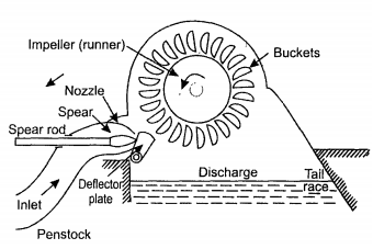
Water supplied is from a high head through a long conduit called a penstock. The water is accelerated in the nozzle and the head is converted into velocity and discharges at high speed in the form of a jet at atmospheric pressure. The jet strikes deflecting buckets attached to the rim of a rotating wheel (runner) as shown in Fig. 6-2. The kinetic energy of the jet is lost to the buckets and water discharged at relatively low speed falls into the lower reservoir or tailrace. The tailrace is set to avoid submerging the wheel during flooded conditions. When a large amount of water is available the power can be obtained by connecting two wheels to a single shaft or by arranging two or more jets to a single wheel.
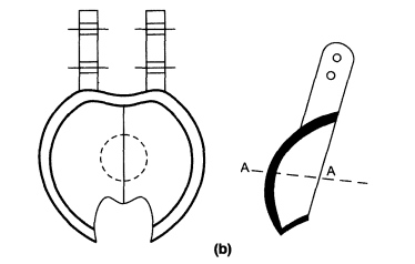
The buckets are double hemispherical. The water strikes the bucket in the center and flows, out at both sides making a U-turn. The surface inside the buckets is polished and smooth to reduce hydraulic losses. A costly material like bronze or stainless steel is generally used for the buckets. The buckets are detachable.
When the load is removed the water is suddenly cut off from the nozzle but it is directed to the deflector plate. The deflector plate that comes into operation cuts off the water supply to the wheel. The water from the deflector plate goes to the tailrace.
The nozzle spear moving inside the nozzle controls water to the turbine. Its operation is explained in the regulation of the turbine.
|
Fig. 6-2 Diagrammatic arrangement of a Pelton wheel.
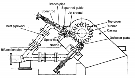
Fig. 6-3 shows two jets for a single runner. The penstock is bifurcated into two pipes leading to two nozzles. The two jets are directed by the runner. All the peripherals, deflector plate, spear are there as in a single jet.
|
Fig. 6-3 Pelton Wheel with 2 jets.
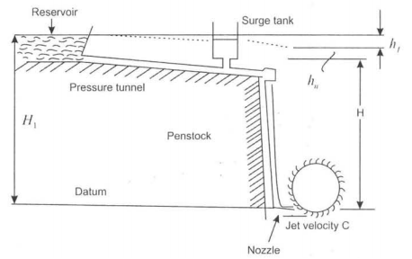
Pelton wheel installation is shown in Fig 6-4. The water supply is from a constant head reservoir at an elevation H1 above the centerline of the jet. A surge tank is installed to dump out any fluctuations of pressure in the penstock. At the end of the penstock is the nozzle which converts head into velocity as jet.
|
Fig. 6-4 Pelton Wheel Hydroelectric Installation.
The total head available from the reservoir above the nozzle is H1
Head loss in pressure tunnel and penstock due to friction = hf
Head loss in the nozzle = hn
Net head available for power generation at the exit of nozzle = H
H=H1 - hf -hn
Where hf = flv2/2gd
Where.
Where
l = length of penstock
v = Velocity in penstock
d = diameter of penstock
f = coeff. of friction
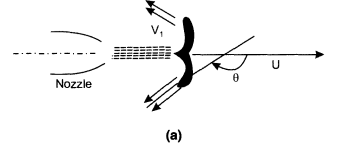
In practice, the penstock is usually sized so that at rated power the net head is usually 85-95% of the total head. The net head is taken to calculate the hydraulic efficiency of the turbine. The jet strikes the bucket at the center and takes a tum of almost 1800 and leaves on both sides of the bucket as shown in Fig, 6-5( a), (b)
|
|
Fig. 6-5 (a) Jet impingement (b) double hemispherical shape of buckets.
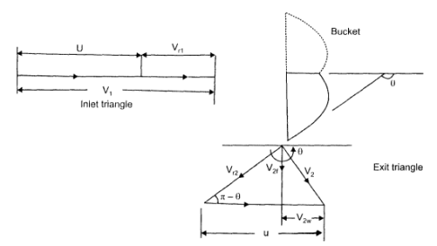
The velocity of the jet is given by VI =√2gH (6.2) The inlet and exit velocity diagrams are shown in Fig 5 J. The total energy transferred to the wheel is given by Euler's Equation.
As the turbine is axial the tangential velocity is the same at inlet and exit ul = u2 = U so that eq. 6.3 becomes
|
|
Fig. 6-6
The inlet velocity triangle is a straight line, we have V rl = VI - u and VIw = VI Also, Vr2 = k Vri, where k is coefficient ot-velocity due to friction. The relative velocity vr2 is tangential to the exit tip of the buckets. Superimposing peripheral velocity u we obtain absolute velocity V2. The velocity Vr2 makes an angle θ with the central line of the bucket. Vr2 = k Vri = k(VI - u) thus V2w = u - Vr2 cos (π-θ) Vr2 = U + Vr2 cos θ V2w = U + k (VI - U ) cos θ Writing Euler's equation
Substituting, V2w = u + k(VI - u) cos θ ; as VIw = V1. we have
The equation shows that there is no energy transfer when the bucket velocity u is either zero or equal to jet velocity V I. It is reasonable to expect therefore the maximum energy transfer will occur at some intermediate velocity of the bucket velocity. Thus differentiating E for u and equating to zero for maximum energy transfer
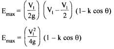
Hence, We have u/V1=1/2 Thus tangential velocity is half the jet velocity for maximum energy transfer. Substituting this value in eq 6.6
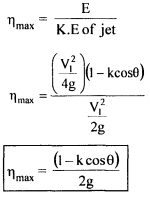
Inlet kinetic energy to the jet= V12/2g Thus maximum theoretical hydraulic efficiency of Pelton wheel,
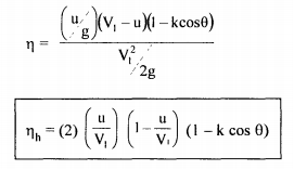
In an ideal case when θ = 180°, k = I; nmax = 100%. In practice, friction exists and the K value is in the region of 0.85 - 0.9 and also the value of θ = 165° to avoid interference between incoming and outgoing jets. Therefore u/V1 is always less than 0.5. For u/V1= 0.46 and θ = 165° , the maximum efficiency is around 90%. Rewriting equation 6.6, E = u/g(VI - u) (I - kcos θ) and also K.E of jet = V12/2g and hydraulic efficiency as
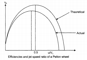
Fig. 6.7 shows the variation of Pelton wheel efficiency with speed ratio u/V1 theoretical and actual.
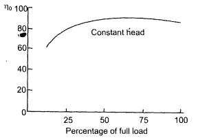
Fig. 6-7 Graphs of theoretical and actual hydraulic efficiency with u/V1 ratio. Fig. 6-8 shows the variation of load with overall efficiency. At low loads less than 35% the efficiency is low but at higher loads, the efficiency is fairly constant around 90%.
Fig. 6-8 Overall efficiency against turbine load (%).
|
Key Takeaways:
- Pelton turbine is an impulse turbine as there is no pressure drop across the buckets. The flow is axial, i.e., there is no change in peripheral velocity, and water enters and leaves the buckets at the same radius. Pelton turbine is chosen when operating head is more than 300 m.
- The major components are a penstock, runner, surge tank, buckets, etc.
- The jet velocity for maximum energy transfer is given by
|
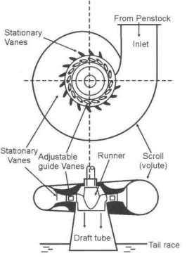
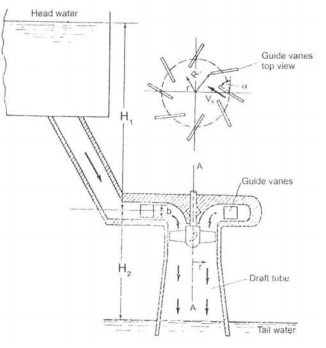
A sketch of a Francis turbine is shown in Fig. 6.9. The flow is contained in a spiral casing called a volute that channels the water into the runner. The volute has a decreasing area to maintain uniform velocity, to the row of stationary vanes.
|
Fig. 6-9 Main components of Francis turbine.
The water passes through a row of fixed guide vanes followed by adjustable guide vanes. The flow can be varied when the turbine is working at partial loads by changing the cross-sectional area between the guide vanes. The water then passes through the runner with radial vanes. The water enters the runner at a large radius and leaves the runner blades at a smaller radius. The interaction between the fluid and runner blades results in torque applied to the runner. The runner is connected to the driving shaft to drive an electric generator. The turbine shown in Fig. 6.9 is vertical type.
The water after doing the work leaves through the draft tube. It is essentially a diffuser whose area increases in the direction of the fluid flow. As area increases velocity decreases and pressure rises.
It produces a negative pressure at the turbine exit and thus increases the head over the turbine which means more power.
There is energy loss at various components from the reservoir to the tailrace. There is energy loss in the penstock conveying water to the turbine losses in fixed guide vanes, and also adjustable guide vanes, and runner vanes. There is also head loss in the draft tube and residual kinetic energy loss at the exit from the draft tube.
Let
H - Total head available to the turbine
Vo - Absolute velocity of water at inlet to stationary vanes
VI - Absolute velocity of water at the exit to adjustable guide vanes
V2 - Absolute velocity of water at the exit to runner vanes
Vrl - Relative velocity at the inlet to runner vane
Vr2 - Relative velocity at the exit to runner vane
ul - Peripheral velocity at the inlet to runner vane
u2 - Peripheral velocity at the exit to runner vane
Vlw, V2w - Whirl velocities at inlet and exit of runner vane
VIf, V2f - Flow velocities at inlet and exit of runner vane
α1 - Guide vane angle
β1 - Runner blade inlet angle
β2 - Runner blade exit angle
|
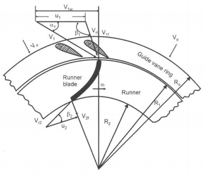
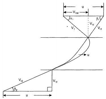
Fig. 6.10 Inlet and exit velocity diagram.
The inlet and exit velocity diagrams of the runner vane are shown in Fig. 6.10.
we have
|
The water comes out from the guide vanes at absolute velocity V1 at an angle α1 to the direction of rotation. The peripheral velocity u1 is subtracted from VI to give relative velocity Vrl at angle β1 to the direction of rotation is obtained.
At the exit, the water leaves the runner blade at relative velocity Vr2 which makes an angle β2 with the direction of rotation. Superimposing u2 absolute velocity V2 is obtained.
If the whirl velocity at exit is zero, V2w = 0, which means that velocity V2 has no horizontal component or α2 = 90°, then Euler's for maximum efficiency is given by
|
In such a case flow velocity at exit V2f = V2 tan β2 = V2/u2 = V2f/u2 so that β2 can be determined.
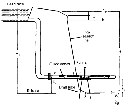
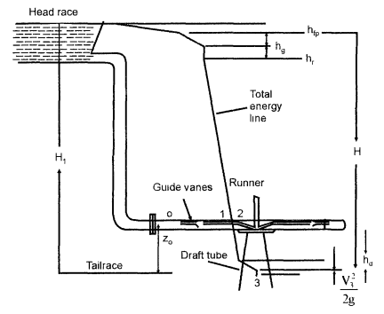
The energy distribution through a hydraulic reaction turbine is shown in Fig. 6-11.
|
Fig. 6-11 Energy distribution through a reaction turbine.
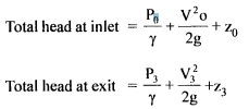
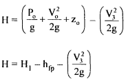
Net head available H across the turbine is the difference in total head between inlet flange (exit of penstock) and tailrace water level
Net head across the turbine
But P3 = atmospheric pressure = 0; z3 is tail race taken as datum z3 = 0, thus eq. 6.10 becomes
where hfp = hydraulic losses in the penstock. The hydraulic efficiency is given by,
Thus,
Energy developed in the runner in terms of Euler's head E = H - hfp - hg - hr - hd where hfp - hydraulic losses in the penstock hg - hydraulic losses in guide vanes hr - hydraulic losses in runner vanes hd - hydraulic losses in the draft tube
|
Working Proportions of Francis Turbine
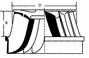
Let B breadth/width of runner vane D diameter of runner z number of runner vanes t thickness of runner vane n ratio of width to the diameter of the runner X Flow ratio ø speed ratio Vf flow velocity √2gH Jet velocity - n = B/D The value of n varies from 0.1 - 0.45 v - Flow ratio X =Vr/√2gh its value varies from 0.15 - 0.3 - Speed ratio ø = u/√2gh its value varies from 0.6 - 0.9 - Flow through runner vanes = flow area x velocity of flow Area (inlet) = (πD1-zt) Bl = πD1K1B1 where k is a factor that allows for the thickness of runner vanes. Area (exit) = (πD2-zt) B2 = πD2K2B2 where K2 is a factor that allows for the thickness of runner vanes. Flow rate Q = (πD1-zt1) Bl VIf = (πD2-zt)B2 V2f Q = πDlBl KlVlf = πD2B2 K2V2f Q = πDl2n1KlVlf = πD22n2K2V2f (6.13) if Kl = K2, V1f = V2f; nl = n2, then equation becomes BlDl = B2D2 The number of runner vanes varies from 16 to 24. The number of runner vanes should be either one more or less than the number of guide vanes to avoid periodic impact. Fig. 6-12 shows the runner of the Francis turbine. As indicated B is the breadth of the runner and D the diameter
Fig. 6-12 Runner of Francis turbine.
|
Specific Speed of Hydraulic Turbines
The specific speed is a dimensionless parameter associated with a given family of turbines operating at maximum efficiency with known values of & angular velocity ω head H, and power output P.
The specific speed is given by
|
where
ω = angular velocity in rad/s
P = power output in Watt
ρ = density of water in kg/m3
H = head over the turbine in meters
g = acceleration due to gravity in m/s2
A preliminary selection of the appropriate type of turbine for a given installation is based on a specific speed ωT.
Key Takeaways:
- In a Francis turbine, the flow is contained in a spiral casing called a volute that channels the water into the runner. The volute has a decreasing area to maintain uniform velocity, to the row of stationary vanes.
- The flow rate is given by Q = πDl2n1KlVlf = πD22n2K2V2f
And the specific speed is given by
|
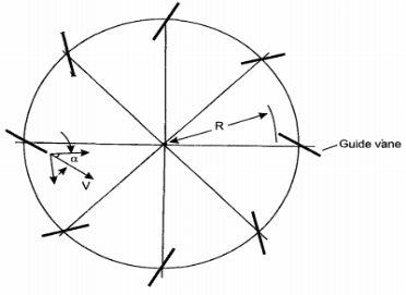
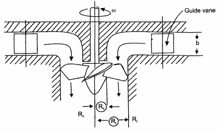
The Kaplan type consists of an axial flow runner with 4 to 6 blades of an aerofoil shape. The spiral casing and guide vanes are similar to the Francis turbine. The flow enters the runner through guide vanes which can be set to any desired angle (within limit) to accommodate changes in power output demand. The runner blades are fixed and cannot change their position. The guide vanes ring is in a plane perpendicular to the shaft so that flow is radial. The runner is situated further downstream so that between guide vanes and the runner the fluid turns through a right angle into the axial direction. The runner blades are long to accommodate a large flow rate and therefore pitch/chord ratio of runner blades is 1 to 1.5 and hence the number of blades is small. The propeller type has a low head between 5-80 m. Fig. 6-13(a) shows the plan view of guide vanes and Fig.6-13(b) shows the profile of the system.
|
Fig.6-13 (a) Plan view of guide vanes
|
Fig. 6-13(b) Axial-flow propeller-type turbine, guide vanes, and runner
Velocity Diagram
The runner blades are long and there is a large difference in radii between the hub and tip of the blades. Therefore velocity diagrams are drawn at the mean radius of the blade. The axial flow velocity is constant as inlet and exit and hence
VIf= V2f = Vf
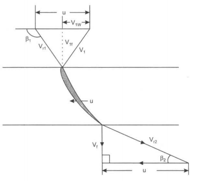
The inlet velocity diagram is constructed by subtracting blade velocity vector u from absolute velocity vector V1 which makes an angle αl to u to obtain relative velocity Vrl as shown in Fig. 6-14.
|
Fig 6-14 Inlet and exit velocity diagrams.
For shock-free entry, the relative velocity Vrl must be tangent to the inlet tip of the blade. The velocity Vrl makes an angle βI with horizontal. The exit velocity diagram is constructed by drawing relative velocity at exit Vr2 tangential to exit tip of the blade, superimposing peripheral velocity u, we obtain absolute velocity V2 which is axial. The velocity diagrams are shown in Fig. 6-15.
|
Fig. 6-15 Inlet and exit velocity diagram.
For maximum efficiency, the whirl component V2w at exit must be zero because velocity V2 is axial and also V2 = V2f
Writing Euler's equation as
|
From the inlet diagram, we have
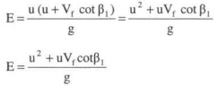
V1w = u-Vf cot (180-β1)=u+Vf cot β1 Substituting this value of V Iw in eq. 6.16
|
If E is constant along the blade radius, Vf is constant over the cross-sectional area, then u increases from hub to tip, u cot β1 must decrease to keep E constant that means β1 must increase from hub to tip and the blade must therefore be 'Twisted'. The profile of the twisted blade changes along the length of the blades. It is difficult to manufacture twisted blades than constant profile (cylindrical) blades. The long blades are cast as an integral part of the tile runner or welded to the hub. In practice, the runner blade is divided into several regions of flow around the blades. The velocity diagrams are drawn for such domain and the power developed computed.
Flow rate is given by the equation Q = area x Velocity of flow
where D1 = diameter at the tip Dh = diameter at the hub Vf = flow velocity Hydraulic efficiency is runner power by hydraulic power
We get,
|
H is effective head H = H1+ H2 as shown in Fig. 6-15 of Kaplan turbine installation. Fig. 6-16 shows overall efficiency against the percentage of design power for various turbines.
|
Fig. 6-16 Axial flow turbine
The characteristic curve for the axial flow Kaplan turbine is similar to the radial flow Francis turbine. The Pelton efficiency curve is flatter but maximum efficiency is lower than Francis turbine. Kaplan has better characteristics than propeller type. The two methods of determining the specific speed of propeller/Kaplan turbine is
given below:
And
|
Key Takeaways:
- The Kaplan type consists of an axial flow runner with 4 to 6 blades of an aerofoil shape. The spiral casing and guide vanes are similar to the Francis turbine. The runner blades are long to accommodate a large flow rate and therefore pitch/chord ratio of runner blades is 1 to 1.5 and hence the number of blades is small.
- The flow rate is given by
|
3. Specific speed is given by
|
Selection of turbine type and determination of plant capacity, turbines require the detailed information on head and possible plant discharge be collected accurately of different conditions.
In a theoretical sense, the turbine output, E, can be expressed mathematically as,
E= F (h, q, TW, d, n, Hs, Pmax)
It can be seen that numerous parameters can be varied to achieve the best selection. The usual practice is to base selection on the annual energy output of the plant and the cost of the corresponding installation.
The following points should be considered while selecting the right type of hydraulic turbines for a hydroelectric power plant.
1) Specific speed:
High specific aped is essential where the head is low and output is large because otherwise, the rotational speed will be low which means the cost of turbo-generator and powerhouse will be high. On the other hand, there is practically no need of choosing a high value of specific speed for high installations, because even with lo specific speed high rotational speed can be attained with medium capacity plants.
2) Rotational speed:
Rotational speed depends upon a specific speed. Also the rotational speed of an electrical generator with which the turbine is to be directly coupled depends on the frequency and number of pairs of poles. The value of the specific speed adopted should be such that it will give the synchronous speed of the generator.
3) Efficiency:
The efficiency selected should be such that it gives the highest overall efficiency of various conditions.
4) Part load operation:
In general, the efficiency at part loads and overloads is less than that with rated (design) parameters. For the sake of the economy, the turbine should always run with maximum possible efficiency to get more revenue.
When the turbine has to run at part or overload conditions Deriaz turbine is employed. Similarly, for low heads, the Kaplan turbine will be useful for such purposes in place of the propeller turbine.
5) Cavitations:
The installation of water turbines of reaction type over the tailrace is affected by cavitations. The critical values of cavitation indices must be obtained to see that the turbine works in a safe zone. Such values of cavitation indices also affect the design of the turbine, especially of Kaplan, propeller, and bulb types.
6) Deposition of turbine shaft:
Experience has shown that the vertical shaft arrangement is better for large-sized reaction turbines, therefore, it is almost universally adopted, whereas, in the case of large size impulse turbines, horizontal shaft arrangement is preferable.
7) Available head and its fluctuation:
a) Very high (350m and above): for heads greater than 350m, Pelton Turbine is generally employed and practically there is no choice except in very special cases.
b) High heads (150 m to 350 m): in this range either Pelton or Francis turbine may employ. For higher specific needs Francis turbine is more compact and economical than the Pelton turbine that for the same working conditions would have to be much bigger and rather cumbersome.
c) Medium heads (60 m to 150 m): a Francis turbine is usually employed in this range. Whether a high or low specific speed would be used depends on the selection of the speed.
d) Low heads (below 60m): between 30m to 60m both Kaplan and Francis turbines may be used. Francis is more expensive but yields higher efficiency at part loads and overloads. It is therefore preferable for variable loads. Kaplan turbine is generally employed less than 30m. Propeller turbines are, however, commonly used for heads up to 15m. They are adopted only when there is practically no load variation.
8) Water quality: (i.e. sand content chemical or other impurities)
Quality of water is more crucial for the reactive turbine than in reaction turbines. Reactive turbines may undergo rapid wear in high-head reactive turbines.
Key Takeaways:
- Selection of turbine type and determination of plant capacity, turbines require the detailed information on head and possible plant discharge be collected accurately of different conditions.
- Various parameters to be considered are specific speed, rotational speed, efficiency, Part load operations, cavitations, Available head, water quality, etc.
A draft tube is connected between runner exit and tail race to obtain a continuous stream of water between them. It is a diverging tube. The pressure increases and velocity decreases in the tube. The tailrace pressure is atmospheric and runner exit pressure is negative (below atmospheric). Then the net head acting on the turbine increases. The turbine works with a larger head and more power is developed by the turbine. This is the main advantage of installing a draft tube. All Francis turbines will have a draft tube. Analysis With references to Fig. 6-17 and applying Bernoulli's equation between point (2) and (3) we get
where hd represents losses in the diffuser also P3 = atmospheric = 0; the tailrace is taken as the datum and therefore Z3 = 0. Re-writing eq. 6.23 with the above assumptions, we have
|
Also V3 < V2 and if hd is neglected, P2/ Y is negative.
The draft tube produces negative pressure at the exit which increases the pressure head over the turbine.
|
Fig. 6-17
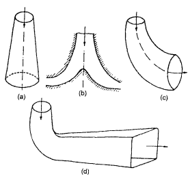
Some of the types of draft tubes are shown in Fig. 6-18.
(a) Straight divergent tube
(b) Moody spreading tube
(c) Simple elbow tube
(d) Elbow tube with circular inlet section and exit rectangular.
|
Fig. 6-18
(PART B)
Pumps and turbines occur in a wide variety of configurations. In general, pumps add energy to the fluid - they do work on the fluid, turbines extract energy from the fluid - the fluid does work on them. Turbo pumps are used to raise the level of the potential energy of the fluid and are widely used in hydro and thermal power plants, chemical industries, buildings, and deep wells. They have relatively few moving parts and reasonable efficiency.
A turbopump is a power-absorbing machine which means it requires a driver, an electric motor, or an I.C. engine. A turbopump essentially consists of blades, flow channels around an axis of rotation to form a rotor. Rotation of rotor produces dynamic effects that add energy to the fluid.
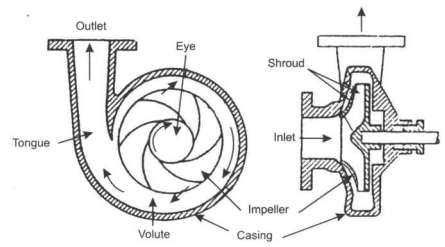
One of the most common radial flow turbomachines is a centrifugal pump. This type of pump has two main components. An impeller attached to the rotating shaft, and a stationary casing, housing, or volute enclosing the impeller. The impeller consists of several blades (usually curved) also sometimes called vanes, arranged in a regular pattern around the shall. A sketch of a centrifugal pump is shown in Fig. 6-19.
|
Fig. 6-19 Schematic diagram of basic elements of a centrifugal pump.
Working of Centrifugal Pump
As the impeller rotates the fluid is sucked in through the eye of the impeller and flows radially outward. Energy is added to the rotating blades and both pressure and absolute velocity are increased as the fluid flows from the eye to the periphery of the vanes. The fluid then discharges directly into a volute chamber.
The volute is designed to reduce velocity and increase pressure. The volute casing with an increase in area in the direction of the fluid is used to produce essentially a uniform velocity distribution as fluid moves around the casing into discharge opening.
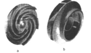
Impellers are of two types - open impeller and enclosed or shrouded impeller. An open impeller is shown in Fig. 6-20(a) where blades are arranged on a hub or backing plate and are open on the other (casing or shroud) side. The shrouded impeller is shown in Fig. 6-20(b) where blades are covered on both hub and shroud ends. A shrouded impeller will have no peripheral leakage.
|
Fig. 6-20 (a) open impeller (b) shrouded impeller.
Pump impellers can be single or double suction. For the single-suction impeller, the fluid enters through the eye from one side of the impeller, whereas in the double suction impeller the fluid enters from both sides of the impeller. The double suction type reduces end thrust on the shaft.
Pumps can be single-stage or multi-stage. For a single-stage pump, only one impeller is mounted on the shaft, whereas for a multi-stage pump, several impellers are mounted on the same shaft. The stages are arranged in series, i.e., discharge from one stage enters flows into the eye of the second impeller, and so on. The flow rate is the same from each stage but the pressure rises in each stage and therefore at the end of the last stage a very large pressure or head can be developed by multistage.
Analysis
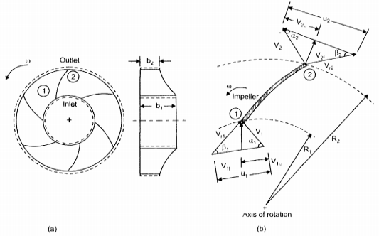
Fig. 6-21 shows the radial flow impeller. The velocity diagram is drawn at the inlet location I and exit location 2.
|
Fig. 6-21 (a) Radial flow impeller (b) velocity diagram.
For the idealized situation in which there are no losses, the theoretical pressure head across the pump is given by Euler's equation.
From the law of cosines, we can write Vr12= u12+ v12 – 2uV1 cos αl (6.26) Vr22 = u22 + v22 - 2uV2 cos α2 Substituting values of uV1w cos αl and uV2w cos α2 in equation 6.25.
The first term on the right hand represents a gain in the kinetic energy as the fluid passes through the impeller, the second term accounts for the increase in pressure across the impeller. Applying Bernoulli's equation between points I and 2, we have
where HI head developed by the pump
Since (Z2 - ZI) is often much smaller than (P2 – PI)/ Y it can be eliminated and thus the static pressure rise from equation 6.28 is given by
Returning to equation 6.25
The best design for a pump would be one in which angular momentum entering the impeller is zero, so that maximum pressure rise can take place, thus if u1V1w= 0; ul ≠ 0, Vlw = 0 i.e. αl = 90° then V1= V1f and equation (6.25) becomes
From triangle geometry of Fig. 6.21 b
Applying the equation of continuity in the region of the impeller, the flow rate is given by Q= π D2b2V2f where D2 is the diameter of the impeller at the exit b2 is the width and V2f flow velocity
substituting this value in Eq. (6.31)
Equation 6.32 is of the form HI = al - a2Q where al and a2 are a function of machine geometry.
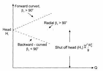
The constant al = u22/g represents the ideal head developed by the pump for zero flow rate and it is referred to as "shut off" head. The slope of the curve of head versus flow rate depends on the sign and magnitude of a2
|
• Radial vanes: for radial vanes β2 = 90°, and a2 = 0. The whirl component of absolute velocity V2w at exit is equal to peripheral velocity u2 and the head is independent of flow rate as shown in Fig 6.22.
Backward curved vanes: for backward-curved vanes β2 < 90° and a2 > 0, then from exit triangle of velocity V2w > u2 and head decreases with flow rate as shown in Fig.6.22.
Formed curved vane: for forward-curved vanes, β2 > 90° and a2 < 0 then from exit velocity triangle Vw2 > u2 and head increases with flow rate as shown in Fig. 6.22.
|
Fig. 6.22 Graphs showing head versus flow rate for various types of pumps.
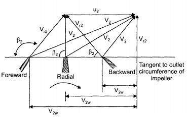
For actual pumps, the blade angle β2 falls in the range of 15 - 35°, with a nominal range of 20° < β2 < 25° and with 15° < β1 < 50°. Pumps are not usually designed with forward-curved since such pumps tend to suffer unstable flow conditions.
Fig. 6.23 shows the effect of blade angle β2 at the outlet on the exit velocity triangle. For same peripheral velocity u2, for forward-curved vane V2w > u2, for radial vane u2 = V2w and for backward-curved vane V2w < u2.
|
Fig. 6-23 Effect of blade angle β2 on exit velocity diagram.
For real fluid flow, the theoretical head cannot be acquired in practice due to losses in the pump
H = Ht - hf (6.33) H = actual head Ht= theoretical head hf= hydraulic losses Hydraulic efficiency is defined as actual head to theoretical head
Mechanical efficiency is the output of the pump divided by input shaft power
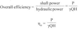
Overall efficiency is defined as power output divided by the power input
Following relation holds good
where T is the torque applied to the shaft
|
Specific Speed
It is possible to correlate a turbopump of a given family to a dimensionless number that characterizes its operation at the maximum condition. Such a number is termed specific speed and is given by
|
Where ω = angular velocity in rad/s
Q = flow rate in m3/s
H = head in meters
g = acceleration due to gravity in m/s2
The value of ω is usually based on motor requirement and values of Q and H are those at maximum efficiency. The type of pump is selected based on the value of ωp. For
ωp < I radial flow pump
1< ωp <4 mixed flow pump
ωp > 4 axial flow pump
Key Takeaways:
- The key components of a centrifugal pump are the eye, the casing, the shroud, the volute, the impeller, and the tongue.
- Pump impellers can be single or double suction. For the single-suction impeller, the fluid enters through the eye from one side of the impeller, whereas in the double suction impeller the fluid enters from both sides of the impeller. Pumps can be single-stage or multi-stage. For a single-stage pump, only one impeller is mounted on the shaft, whereas for a multi-stage pump, several impellers are mounted on the same shaft.
 The flow rate is given in the impeller is given by Q= π D2b2V2f and the head developed by the pump is given by
|
Cavitation
Cavitation is the result of insufficient pressure at the suction end of the pump or Net Positive Suction Head Available (NPSHa) causing the liquid in a pump to turn into vapor at low pressure.
At low pressures, this creates air bubbles that implode as the liquid moves from the suction side of the impeller to the delivery side.
The air bubble implosion generates a shockwave that stresses the pumps’ internal surfaces, creating vibration and mechanical damage, and can ultimately fail.
When this occurs repeatedly, cavitation can cause pitting and fractures in the impeller, volutes, and casing, weakening the metal, increasing resistance to flow and reducing pumping efficiency. The shock loads from cavitation can also decrease the service life of the shaft and motor.
Cavitation and the related problems it causes can greatly impact the life of a pump, reducing it by 10-15 years, or even more in extreme cases.
Cavitation is most easily avoided during the design stage, ensuring the chosen pump will have sufficient NPSHa so that the liquid remains above vapor pressure.
The NPSH will need to be calculated for each application as vapor pressure is different for different liquids and varies with pressure and temperature.
This can then be used when selecting a pump as manufacturers will be able to provide the Net Positive Suction Head Required (NPSHr) for any of their pumps to match it with the specifications.
Corrosion
Corrosion in pumps is the result of a chemical reaction between the metal and the fluid being pumped.
This reaction can cause uniform corrosion of the wet surfaces – found mostly in pumps made from non-stainless steel materials – or localized corrosion of a small portion of the components – occurring most commonly in metals that form oxide layers that adhere to and passivate the surface.
When corrosion does occur, pump performance and efficiency can be affected, increasing the need for more frequent maintenance and more downtime, and if left untreated it can lead to failure.
The key to mitigating corrosion is by selecting a pump manufactured from the most appropriate materials for the application.
Cast iron is amongst the cheapest options for pump materials and is often used for casings.
It has good corrosion resistance to neutral and high pH liquids, making it a popular choice for general purposes, irrigation, and mining pumps. However, it is not suitable for low pH applications where it is more prone to corrosion.
Stainless steel is one of the most commonly used materials for pumps as it has good corrosion resistance in a wide range of environments where other carbon and low alloy steels would corrode.
Under some circumstances, such as exposure to aqueous environments where chloride is present, pitting corrosion may occur on lower grades of stainless steel.
However, this is not an issue for higher grades of stainless steel, which have a high level of corrosion resistance.
Therefore, corrosion is most easily avoided when selecting a pump.
Material selection will determine corrosion resistance in a particular application as well as the pump’s overall cost, including initial cost, maintenance, replacement, downtime, lifecycle, and reliability.
Fouling
Fouling occurs when particulate matter adheres to a pump’s internal surfaces, most commonly in the distribution lines connected to the intake or outflow.
When this occurs, pumping efficiency and flow capacity are decreased, and may eventually lead to failure. This is an unavoidable problem but is more prevalent in applications where the fluid being pumped contains particles.
However, various cleaning methods can be used to maintain the pump and improve efficiency and capacity.
Wear
Wear is inevitable when running a pump, however, there are a few factors that can cause excessive wear, speeding up the deterioration of the pump.
Particulate matter in the pumped fluid can lead not only to fouling but also increases the pace of wear on a pump.
These particulates scour a pump’s interior surfaces and roughen them, reducing pumping efficiency over time as it needs to work harder to move the fluid.
Eventually, the pump will become so worn that it will be unable to produce enough lift and may cause excessive vibration.
Wear can also be the result of an improperly sized pump which can cause an imbalance of pressure, putting undue stress on the bearings and seals; turbulence; fluid velocity; deterioration of wear rings; and erosion and corrosion.
The wear rate can be slowed down by ensuring the pump size and materials are suitable for the application, and regular maintenance is carried out to find and fix any problems before they result in unexpected downtime or pump failure.
Key Takeaways:
- The most common problems in pumps are due to Cavitation, Corrosion, Fouling, Wear, Leakage, etc.
- These can be prevented by regular maintenance and cleaning, Skilled handling, proper material usage, proper design, etc.
On the suction side of the pump low pressures are commonly encountered, with the possibility of cavitation occurring in the pump. Cavitation occurs when the liquid pressure at a given location is reduced to the vapor pressure of the liquid. When this occurs, vapor bubbles form. This phenomenon can cause a loss in efficiency as well as structural damage to the pump when these bubbles collide with the metal surface. The cavitation has to be avoided in the pump. To characterize the potential for cavitation the difference between the total head on the suction side and the vapor pressure head is used. The difference is called net positive suction head (NPSH)
The total head near the pump impeller is
|
Liquid vapor pressure head is
Pv/ γ, where Pv is vapor pressure at the location.
|
(6.39)
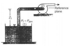
Consider a schematic of pump installation shown in Fig. 6-24 to illustrate NPSH
|
Fig. 6-24 Schematic of pump installation in which pump must raise liquid from one level to another.
For typical flow system shown in Fig. 6-24 and applying energy equation between free liquid surface, when the pressure is atmospheric and a point on the suction side of the pump near the impeller yields.
where hl represents hydraulic losses between the free surface and pump impeller inlet. Thus head available at the pump inlet is
Substituting this value in Eq. 6.39 of NPSH
|
For this calculation, absolute pressures are to be used since vapor pressure is in absolute units.
Key Takeaways:
- To characterize the potential for cavitation the difference between the total head on the suction side and the vapor pressure head is used. The difference is called net positive suction head (NPSH)
- Net Positive suction head is given by
|
References:
1. Fluid Mechanics – Streeter-McGraw-Hill International Book Co., Auckland.
2. Flow in open channel – V. T. Chaw - McGraw-Hill International Book Co., Auckland.
3. Fluid Mechanics – K. L. Kumar – Eurasia Publication House, Delhi.
