Unit-1
Principal Plane and Stress
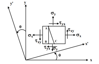
Consider a general plane stress in x-y co-ordinate system. We now want to transform this to another stress system in, say, x′- y′ co-ordinates, inclined at an angle θ from the side. This is shown in figure.
|
Fig. 1 Transformation of stress system
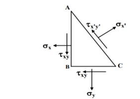
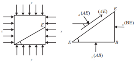
A two-dimensional stress acting on the faces of a cubic element is shown in fig. In plane stress assumptions, the non-zero stresses are σx, σy and τxy=τyx. We may now isolate an element ABC such that the plane AC is inclined at an angle θ and the stresses on the inclined face are σ′x and τ′xy .
|
Fig. 2 - 2D stress acting on faces of cubic elements
Location of the plane stress in this transformation is given by
Location of principal plane
|
This is the formula which relates the angle θ with the stresses acting on the body.
STRESSES ON OBLIQUE SECTION OF BODY SUBJECTED TO A DIRECT STRESS IN ONE PLANE
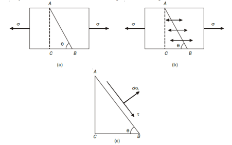
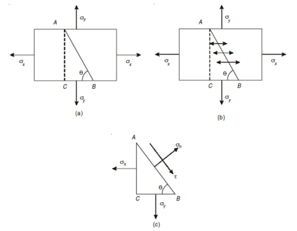
Assume a rectangular body with uniform cross-sectional area of unit thickness subjected to direct tensile stress in X-X axis. Now, consider an oblique section AB inclined with the axis X-X.
|
Fig. 3 Stress distribution
Let, σ = tensile stress across the face AC, θ= angle, which AB makes with BC i.e. with the X-X axis We know that horizontal force acting on the face AC is Resolving the force perpendicular to the section AB, Now resolving the force tangential to section AB We know that normal stress across the section AB,
Shear stress acting, Resultant stress is given by, |
Example 1 A wooden bar is subjected to a tensile stress of 5 MPa. What will be the values of normal and shear stresses across a section, which makes an angle of 25° with the direction of the tensile stress
Given: Tensile stress (σ) = 5 MPa and
angle made by the section with the direction of the tensile stress (θ) = 25°
|
Fig. 4 Example 1
Solution
Normal stress across the section:
= = 0.89 MPa Shear stress across the section, = 2.5 × 0.766 = 1.915 MPa
|
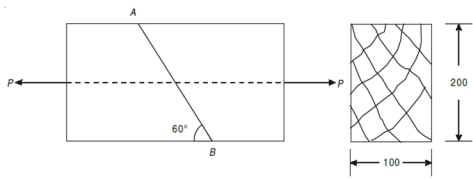
EXAMPLE 2 A tension member is formed by connecting two wooden members 200 mm × 100 mm as shown in Fig Determine the safe value of force (P), if permissible normal and shear stresses in the joint are 0.5 MPa and 1.25 MPa respectively.
SOLUTION
Let, σ = Safe stress in the joint in N/mm2 Normal stress, 0.50 = σ = σ = 0.67 N/mm2 For, shear stress 1.25 = σ = σ = 2.89 N/mm2 from above values, taking the least value of the two values i.e. 0.67 N/mm2 hence, safe value of force is = 0.67 × 200× 100 = 13.4kN
|
STRESSES ON AN OBLIQUE SECTION OF A BODY SUBJECTED TO DIRECT STRESSES IN TWO MUTUALLY PERPENDICULAR DIRECTIONS
|
Fig. 5 Stress distribution
θ = Angle which the oblique section AB makes with x – x axis in clockwise direction. Normal stress across the section AB,
Shear stress (tangential stress) across AB,
when 2θ = 1 or 2θ = 90 or 45, Resultant stress is given as,
|
EXAMPLE 1 A point in a strained material is subjected to two mutually perpendicular tensile stresses of 200 MPa and 100 MPa. Determine intensities of normal shear and resultant stresses on a plane inclined at 30° with the axis of minor tensile stress.
SOLUTION
Normal stress on the inclined plane,
= 150 – 50 × 0.5 = 125 MPa Shear stress on the inclined plane,
= =50 sin60 τ = 43.3 MPa Resultant stress on the inclined plane,
= = 132.3 MPa |
At any point in a strained material (material under stress), there are three planes mutually perpendicular to each other, which carry normal stresses only (tensile, compressive) and no shear stress. The plane in which the maximum normal stress is applied is called as principal plane.
|
Fig. 6 Principal plane
PRINCIPAL STRESS
The magnitude of normal stress across the principal plane is known as principal stress. The determination of the principal plane and stress is important in design of various structures and components.
Analytical and Graphical methods are used for determining stresses on this bodies.
SIGN CONVENTIONS IN ANALYTICAL METHOD
- All Tensile stresses and strains are taken as positive, while all compressive stresses and strains are taken as negative.
- Shear stress which tends to rotate the element in clockwise direction is taken as +ve, while the one which rotates in anticlockwise direction is taken as negative.
This sign conventions are followed throughout the entire course for the compound stresses and strains without any changes.
The two methods of determining the principal stress are given as follows.
ANALYTICAL METHOD:
|
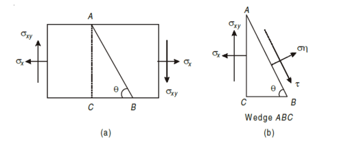
Fig. 7 Rectangular body subjected to stresses
Consider a rectangular body of a uniform cross-sectional area and unit thickness subjected to a direct tensile stress along x – x axis accompanied by a positive (i.e., clockwise) shear stress along X-X axis
Let, σx = Tensile stress in x – x direction. τxy = Positive (i.e. clockwise) shear stress along x – x axis θ = Angle which oblique section AB makes with x – x axis in clockwise direction.
Normal stress is given by, Tangential stress is given by, Resultant stress is given by,
Major principal stress is given by,
|
Minor principal stress is given by,
Location of principal plane
Maximum shear stress,
= ± Major principal strain Minor principal strain
|
GRAPHICAL METHOD:
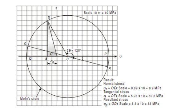
By drawing a Mohr’s circle, the normal, shear and resultant stresses may be determined graphically.
|
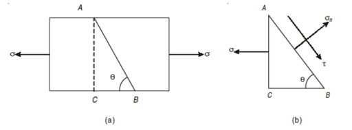
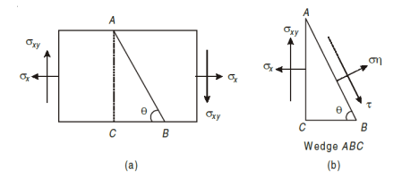
Fig. 8 Rectangular body subjected to stresses
Consider a rectangular body of uniform cross-sectional area and unit thickness subjected to a direct tensile stress along x – x axis as shown in Fig. 2.6 (a, b). Now consider an oblique section AB inclined with x – x axis, on which we are required to find out the stresses as shown in Fig.
σ = Tensile stress, in x – x direction
θ = Angle which the oblique section AB makes with the x – x axis in clockwise direction
STEPS TO DRAW MOHR’S CIRCLE ARE GIVEN BELOW,
1. Draw a horizontal line X – X and take a suitable point O on it.
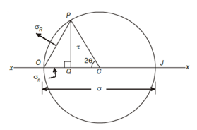
2. Cut off OJ equal to tensile stress (σ) to some suitable scale towards right (because σ is tensile). Bisect OJ at C. Now point O represents the stress system on plane BC and the point J represents stress system on plane AC.
3. Now with C as centre and radius equal to CO or CJ draw a circle. It is known as Mohr’s circle for stresses.
|
Fig. 9 Mohr’s Circle
4. Now through C draw a line CP making an angle of 2θ with CO meeting the circle at P. The point P represents the section AB.
5. Through P, draw PQ perpendicular to OX. Join OP. Now OQ, QP and OP will give normal stress, shear stress and resultant stress and the angle POJ is called the angle of obliquity (θ).
MOHR’S CIRCLE FOR STRESSES ON AN OBLIQUE SECTION OF A BODY SUBJECTED TO DIRECT STRESSES IN ONE PLANE ACCOMPAINED BY A SIMPLE SHEAR STRESS
Consider a rectangular body of a uniform cross-sectional area and unit thickness subjected to a direct tensile stress along x – x axis accompanied by a positive (i.e., clockwise) shear stress along x – x axis
σx = Tensile stress in x – x direction. τxy = Positive (i.e. clockwise) shear stress along x – x axis, and θ = Angle which oblique section AB makes with x – x axis in clockwise direction. |
|
Fig. 10 Rectangular body subjected to stresses
First of all, consider the equilibrium of the wedge ABC. We know that as per principle of simple shear the face BC of the wedge will also be subjected to an anticlockwise shear stress. Now draw the Mohr’s circle of stresses as shown in Fig
|
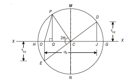
Fig. 11 Mohr’s Circle
1. First of all, take some suitable point O and through it draw a horizontal line XOX.
2. Cut off OJ equal to tensile stress σx to some suitable scale and towards right (As σx is tensile + ve).
3. Now erect perpendicular at J along the line X – X (because τxy is positive along X – X axis) and cut off JD equal to the shear stress τxy to the scale. The point D represents the stress system on plane AC. Similarly, erect a perpendicular below the line X – X (because τxy is –ve along Y – Y axis) and cut off OE equal to shear stress τxy to the scale. The point E represents the stress system on plane BC. Join DE and bisect it at C.
4. Now C as centre and radius equal to CD or CE draw a circle. It is known as Mohr’s circle of stresses.
5. Now through C, draw a line CP making an angle 2θ with CE in clockwise direction meeting, the circle at P. The point P represents the stress system on the section AB.
6. Through P, draw PQ perpendicular to the line OX. Join OP.
7. Now OQ, QP and OP will give the normal, shear and resultant stresses to the scale. And the angle POC is called the angle of obliquity.
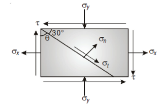
EXAMPLE A point in a strained material is subjected to a tensile stress of 65 N/mm2 and a compressive stress of 45 N/mm2, acting on two mutually perpendicular planes and a shear stress of 10 N/mm2 are acting on these planes. Find the normal stress, tangential stress and resultant stress on a plane inclined to 30° with the plane of the compressive stress
|
Given: Here σx = 65 N/mm2 σy = –45 N/mm2 (Compressive ∴ – ve) θ = (90 – 30) = 60° with the plain of σx. τ = 10 N/mm2 SOLUTION To find: σn, σt, σR. Analytical solution, = = 52.63 N/mm2 Tangential stress, = = 52.63 N/mm2 Resultant stress = 53.36 N/mm2 Angle of obliquity φ = |
|
EXAMPLE
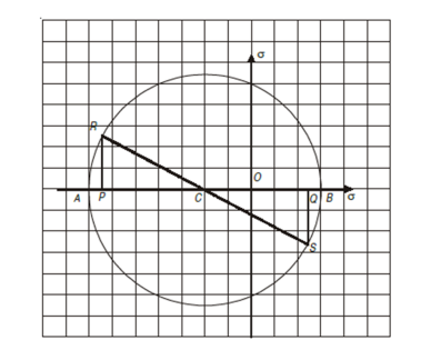
At a point in a body the normal and shear stresses on two perpendicular planes are given as σx = –100 MN/m2, σy = 40 MN/m2, τxy = 50 MN/m2. Using Mohr’s circle determine principle stresses and their planes. Given: σx = –100 MN/m2 σy = 40 MN/m2 τxy = 50 MN/m2 To find: σn1, σn2 and θp Step 1: Select origin O, the rectangular axis through O represents σ and τ. Step 2: Select suitable scale, take 1 cm = 20 MN/m2 Step 3: take OP = σx/20 = -100/20 = -5cm; and OQ = σy/20 = 40/20 = 2cm Step 4: Draw perpendicular from point P and Q such that PR = QS = τ/20 = 50/20 = 2.5cm Step 5: Join RS and mark C on horizontal axis Step 6: Draw a circle of radius CR from centre C Step 7: Mark the point A and B on the horizontal axis which cut by a circle Step 8: OA and OB represent principle stress. Step 9: Angle PCR indicates the angle of principle plane (2θ). |
|
From figure
σn1 = OA × Scale = 5.8 × 20 = 116 N/mm2 (Compressive) σn2 = OB × Scale = 2.8 × 20 = 56 N/mm2 (Tensile) |
The same stresses can be calculated using the analytical way but as we can clearly understand in this numerical finding solution to the principal stresses is much easy in Mohr’s circle method than in the analytical method but the analytical method gives us the more accurate solutions to the problems.
In tensile test, yield point load can be easily determined but in most of machine elements subjected to complex stresses, it is very difficult to know the point of yielding.
To improve design of machine elements, various theories of failures are developed based on physical behavior of material.
VARIOUS THEORIES OF FAILURE
- ‘Maximum Principal Stress theory’ also called Rankine Theory used for brittle materials
- ‘Maximum Shear Stress theory’ also called Coulomb, Tresca and Guest’s theory used for ductile materials
- ‘Maximum Principal Strain theory’ also called St Venant’s theory
- ‘Maximum Strain Energy theory’ also called Haigh’s theory good for ductile materials
- ‘Shear Strain Energy theory OR Distortion Energy theory’ also called Huber von Mises and Hencky’s theory
Maximum Normal Stress Theory
According to this theory maximum principal stress induced in material under complex load condition exceeds the maximum normal strain in simple test, the material fails.
Failure condition, 
 = yield point stress
|
This theory is not suitable to design machine elements as  and
and  are in opposite direction.
Maximum Shear Stress Theory
According to this theory when maximum shear strength in actual case exceeds maximum allowable shear stress in tension test then material fails.
|
This theory is widely used in the analytical way to calculate for the ductile materials. This has proved to be widely used theory for simple calculations in designing of simple machine elements.
Maximum Strain Energy Theory
The energy stored in the material when the material is said to be deformed is called as strain energy. According to this theory when total strain energy exceeds the total strain energy in simple tensile test then material fails.
The condition is given by,
|
This condition gives the limiting condition of the strain energy in the material or else the material will fail.
References
- Strength of Material by S. S. Ratan
