Unit-2
Combined Direct and Bending Stresses
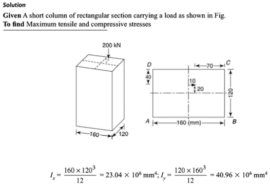
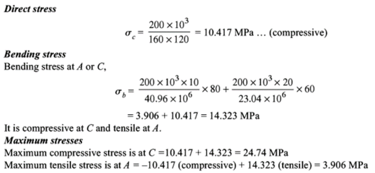
Combined Direct and Bending stresses for eccentric loading
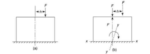
Let a column be acted upon by a thrust F, the line of action of which cuts the cross-section at a point on the x-axis at a distance h from the centroid O. If two equal and opposite forces are introduced along the axis of the column, then the system becomes equivalent to the load at O that produces a uniform direct stress along with a bending moment  about y-axis, producing a varying bending stress.
|
Fig. 1 Eccentric loading on column
Then the combined compressive stresses at any point at a distance  from YY,
|
Where, A is the cross-sectional area
If  taken positive on the same side of the y-axis as the load, then bending stress will be of same type of direct stress and taken and positive. On left side,
  is negative and thus the sign taken is negative. And thus at the left edge o the section, stress will depend upon the value of the right term of the above equation i.e. it is more or less.
Stress distribution is given below:
|
Fig. 2 Stress distribution
The above condition is when the load is eccentric to one axis.
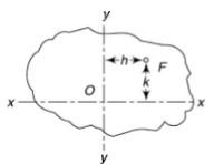
In case, when load is eccentric to both axes as shown below.
|
Fig. 3 Load eccentric to both axis
It will be equivalent to central load and bending moment about the two axes.
In the above equation, x and y are taken positive when on the same side of the axes as of the load.
Core/kernel of a section
In masonry column, it is desirable that tensile stresses are not set up. It is achieved if the line of action of load lies within the central area of the section. This central area is called as kernel or core of the section.
Shape of the kernel depends on the profile of the section.
Middle Third rule for rectangular section
Consider the rectangular section with width b and depth d.
|
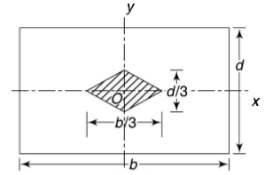
Fig. 4 Core for rectangular section
The tensile stresses may be developed if, x and y are negative.
In limiting cases if
|
This equation gives the limiting values of h and k. In each quadrant the load must lie in the line produced by this equation.
It shows that when the load lies on the either axis, it should lie on the middle third in the cross-section to avoid the tensile stress. Hence, the load must lie in the diamond area. For the rectangular section, maximum eccentricity is |
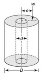
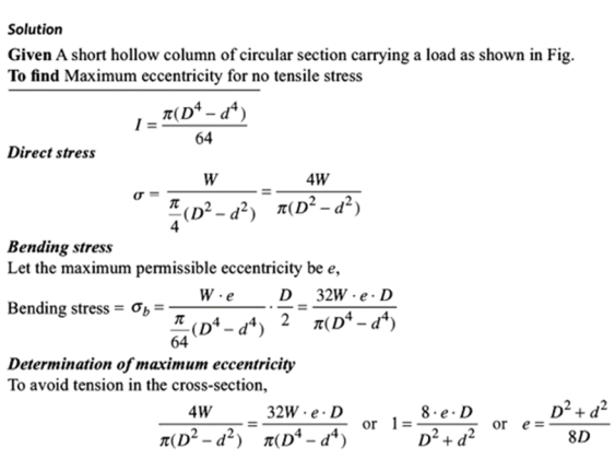
Middle Quarter rule for circular section
Consider the circular section with diameter d as shown below
|
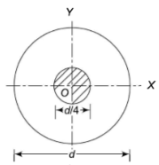
Fig. 5 Core for circular section
The maximum stress along any axis of diameter is
In limiting cases,
|
The equation gives the limiting value of eccentricity for all possible positions of the load. The kernel is the circle of diameter  with center O. To avoid tensile stress, load must lie within this section.
|
|
|
|
Stability of gravity dam:
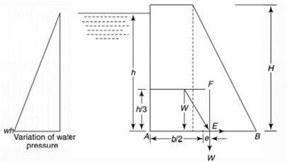
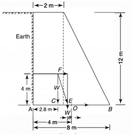
A dam is a structure to store water and to provide head to a power house. Consider as dam as shown in figure.
|
Let H and h be the height of dam and of water on the upstream side respectively.
There are two main forces acting on the dam:
- Force of static water pressure
- Weight of dam
Consider a unit length of dam.
Let W be the weight of the dam acting downward through center of gravity of weight of dam.
If w is the specific weight of water, then wh is the water pressure at the bottom of the dam and its variation is linear, zero at the surface of water and maximum (wh) at the bottom of dam.
Total water force acting on the dam,
|
As the water pressure varies linearly from top to bottom, the center of force is at H/3 from the bottom of the dam.
If b is the width of the dam at the bottom,
Resultant thrust is given by,
|
Let it intersect the bottom of the dam at E.
Horizontal component of R at E is equal to F. This is resisted by the frictional force at the base against sliding.
Vertical component of R at E is equal to W and is balanced by the resultant of stress forces at the bottom.
The vertical component W at E induces
- Normal compressive stress at the base due to load W and
- Normal compressive and tensile stresses due to bending moment induced due to eccentricity of load
Eccentricity of loading,
The bending moment = |
Then the combined stress at any point at a distance  from midpoint of the base,
Tensile stresses may be developed if
|
This indicates that point E must lie between b/6 from midpoint of the base, otherwise the term in the bracket will become negative and tensile stress will occur at the base.
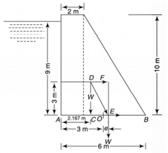
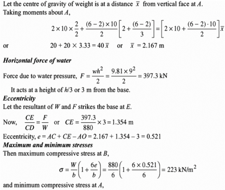
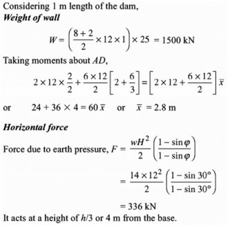
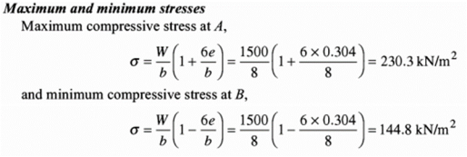
Solution:
|
|
|
Stability of retaining wall:
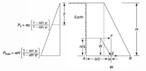
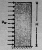
Materials having loose particles such as sand, clay earth, gravel, ash and mud take the shape of a cone when placed freely on a surface. The angle of the cone varies from material. This means that if such a material is placed near a wall, the volume of material which is prevented on the wall varies zero at the top of each to a maximum at the bottom.
The material retained by the wall is known as backfill which may have its top surface horizontal or inclined. The backfill above the horizontal plane at the top of a wall is known as surcharge. In the design of retaining walls, it is necessary to determine the lateral pressure exerted by the retaining mass of soil.
|
Angle of Repose: It is the natural slope of the materials when placed on a horizontal surface in the absence of any external acting force. For most of the materials, its value varies between 20o and 40o.
Rankine’s Formula: This formula provides the earth pressure at any depth y from the top of the retaining wall. It is given by
|
Where  is the specific weight of earth and
  is the angle of repose. If H is the height of the wall, then maximum pressure at the bottom is
|
Total horizontal force = Average pressure x height
|
This force acts at H/3 from the bottom.
|
Solution:
|
|
|
Stability of Chimney:
Consider a chimney having cross-sectional area A and height H subjected to uniform wind pressure  .
.
Weight of chimney,
|
Direct stress at base
|
|
Let wind pressure acts on the surface area comes in contact produced bending of structure.
Total wind pressure = Coefficient of wind pressure x wind pressure x projected area
Where C = Coefficient of wind pressure For plane surface, C = 1 and for circular surface C = 2/3 Bending moment at base M = Total wind pressure x distance of its application from base.
Bending stress
Stress at base
Maximum stress at base
Minimum stress at base
|
References
- Strength of Material by S. S. Ratan
