Unit-3
Influence Line Diagram
The graphical representation of such variation is called as influence line or influence line diagram (ILD). The designer analyses the structures by drawing such type of graph to get critical position of loads.
Thus, the influence line diagram (ILD) may also be defined as a graph of stress resultants like a resultants like a reaction at supports, shear force at section, bending moment at a section for various positions of a unit load on the span of structure.
ILD are linear for determinate structures whereas curvilinear for indeterminate structures.
Uses of ILD:
- To determinate reaction at supports for a given system of loads.
- To determinate the position of load for the maximum reaction.
- To determinate shear force and BM at any section for the given system of loading.
- To determinate the position of loads for maximum SF and BM at a section.
Influence Line Diagram for Simply Supported Beams:
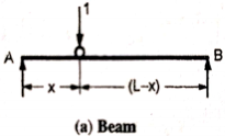
Consider a simply supported beam AB as shown in figure. Let a unit load moves from left end A to the right end of beam B.
|
At any instant, the unit load at a distance ‘x’ from ‘c’.
Therefore,
ILD for RB – When unit load is at ‘A’, x=0 Therefore,
When unit load is at ‘B’, x = L Therefore,
|
Therefore, ILD of RB is a triangle varying from zero ordinate at A and one at B as shown in figure below.
|
ILD for RA –
When unit load is at ‘A’, x= 0
Therefore,
When unit load is at ‘B’, x = L Therefore,
|
Therefore, ILD of RB is a triangle varying from one ordinate at A and zero at B as shown in figure below.
|
ILD for shear force at a given section:
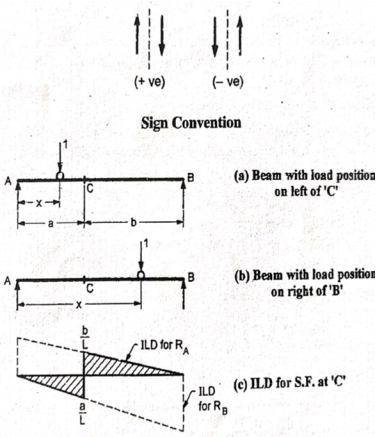
Consider a unit load is moving along the span of a simply supported beam girder AB. Let C be the section for which ILD for shear force has to be drawn.
|
a. When unit load is between A to C, the SF at C is – RB. Therefore, the part of ILD for RB is applicable i.e. between A to C.
b. When unit load is between C to B, then the shear force at C is + RA. Therefore, a part of ILD for RA is applicable i.e. between C to B.
ILD for the BM at a given section –
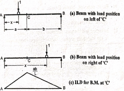
Consider a beam AB is simply supported at ends. Let ‘C’ be the point or section for which we have to draw ILD for BM.
|
a) When unit load is a distance x from A i.e. in between A to C. The moment at C is given by
Since,
Hence,
This equation is applicable for the portion AC, for any position of unit load. At At Therefore, the BM varies from zero at A to ab/L at C shown in figure (c) b) When unit load is at a distance x from A i.e. in between C to B then
Since,
Hence,
This equation is applicable for the portion CB, for any position of unit load. At At Therefore, BM diagram varies form ab/L at C to zero at B as shown in figure (c)
|
Proof
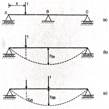
Consider a continuous beam ABC, freely supported at A and C, continuous over B.
Let unit load moves along beam ABC from A to C.
Consider a section x-x at a distance x from A.
To plot the ILD fro reaction RB
Remove the support B, find out the deflection at B.
Let the deflection is yBx
Now, apply unit load at B
Find out the deflection at x due to unit load acting at B, say yxB
Find out the deflection at B due to unit load at B, say, yBB
As per Maxwell’s reciprocal theorem,
This expression gives the reaction at B
To plot ILD for RB, take yBB = 1 |
|
Similarly, to obtain ILD for BM, instead of applying unit load, unit moment is applied at point of required BM. The moment at D
|
Example:
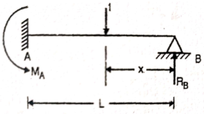
Draw the influence line diagram using Muller Breslau’s principle for the propped cantilever of span L shown in figure fixed at A and simply supported at B for reaction at B and moment at A
Solution:
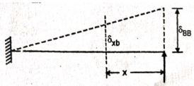
Remove the support B and apply unit load at B Moment C is
|
|
Integrating above equation,
|
Integrating it again we get,
|
Applying boundary condition, at support A, both slope and deflection is zero.
Hence, at Substituting above value,
And at Substituting above values,
Therefore,
Substituting values of C1 and C2
|
This is the general expression of deflection
Deflection at B: At B, Substituting above value in expression of deflection,
We know that, reaction at B,
Put
|
ILD for RB:
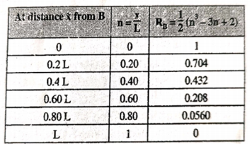
Prepare a table of the values of RB for n ranging from 0 to 1, as under
|
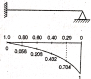
The ILD for RB can now be plotted as shown in figure below
|
b. ILD for moment at A
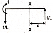
- Remove fixed support A
- Apply unit couple at A
|
iii. Determine slope at A
|
Integrating this equation w.r.t. x
|
Integrating it again we get,
|
|
Applying boundary condition,
Hence, at B At B Substituting above value,
Substituting values of C1 and C2
This is the general expression of deflection And,
At A,
Slope at A
ILD for moment at A
Put
|
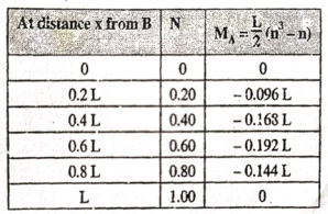
Prepare a table of the values of MA for n ranging from 0 to 1, as under
|
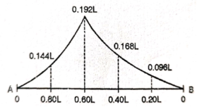
The ILD for moment at A can now be plotted as shown in figure below
|
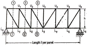
To find the ILD for the forces in member, method of section is used. It gives the simple relation with end reactions, when unit load is not on panel. When the unit load is on the panel point, the forces in the member varies linearly. This method is illustrated with the example given below:
Example:
|
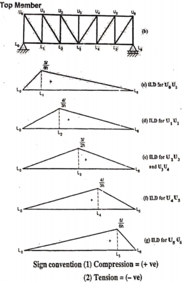
- ILD for Top chord members
Take the section 1 – 1 as shown in above figure. Section 1 – 1 cuts three members. To find forces in U1 U2. We have to take moment all forces about L1 because the remaining two parts are passing through L1, so moment of that member force are zero. When unit load is in left part, consider right part is in equilibrium and vice versa.
b. When unit load is at L1, R2 = 1/6
c. When unit load is in portion L1 to L6, taking moment about L1 we get,
When unit load is at L1, R1 = 5/6
When unit load is at L6, R1 = 0
|
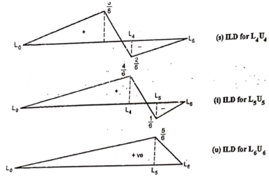
Thus, it is similar to ILD for the moment at L1 divided by height. Similarly, ILD for U1 U2, U2 U3, U3 U4, U4 U5 and U5 U6 may be found by using ILD for the bending moments at L2, L3, L4 and L5 respectively.
|
2. ILD for bottom chord member
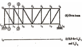
- ILD for L0L1: There should not be any force in member L0L1, through the unit load moves to any panel point. As unit load is vertical, so at the joint L0, no horizontal member or force acts other than L0L1.
|
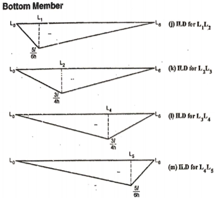
By observation Similarly, ii. ILD for L1 L2 : When unit load is on left part of section, consider right part of section in equilibrium section from figure (h)
When unit load is at L0, R2 = 0
When unit load is at L1, R2 = 5/6
When unit load is on right part,
When unit load is at L1, R2 = 5/6
When unit load is at L6, R1 = 0
|
Thus, it is similar to ILD of the bending moment at U1 divided by height. Similarly, ILD for L2 L3, L3 L4 and L4 L5 may be found by using ILD for the bending moments at U2, U4 and U5 respectively as shown in figure (k), (l) and (m).
|
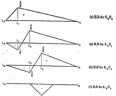
3. ILD for vertical members.
Consider a through truss as shown in figure (n)
|
Take section 1-1 as shown in figure (n) and consider part of section. At L0, When unit load is at L0, R1 = 0
When unit load is at L1, R1 = 5/6
When unit load is at L6, R1 = 0
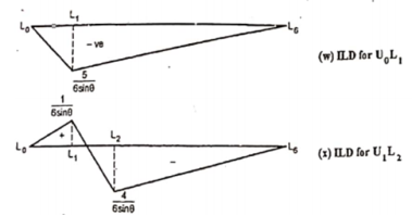
ii. ILD for member U1L1 Take section 2-2 as shown in figure (n) and consider part of section. When unit load is in portion L0 to L1, When unit load is at L0, R2 = 0
When unit load is at L1, R2 = 1/6
When unit load is in portion L2 to L6,
When unit load is at L2, R1 = 4/6=2/3 (compression)
|
Thus, ILD for vertical member at L1 and L2 is the Shear force at the joints respectevly. Similarly forces in members U2L2, U3L3, U4 L4, U5L5, and U6 L6 are shown in figure below.
|
|
4. ILD for diagonal members
To draw ILD for diagonal members take section as shown in figure (v)
|
When unit load is at L0, R2 = 0
For unit load on right part, consider equilibrium of left part
When unit load is at L1, R1 = 5/6
When unit load is at L6, R1 = 0
ii. Consider section 2-2 as shown in figure (v). For unit load on left part, consider equilibrium of right part
When unit load is at L0, R2 = 0
When unit load is at L1, R2 = 1/6
For unit load on right part, consider equilibrium of left part
When unit load is at L2, R1 = 4/6
When unit load is at L6, R1 = 0
|
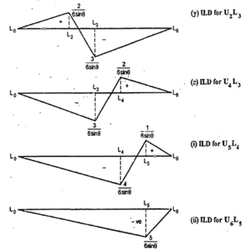
Similarly, ILD for U2L3, U4L3, U5L4 and U6L5 are drawn as shown in figure below
|
|
References
- Structural Analysis by Bhavikatti SS
