Unit-5
Slope and Deflection of Determinate Beams
When the beam is subjected to loading, it deflects from its original position.
The curve in which it bends is called as elastic curve.
The vertical distance at any point in a beam between the elastic curve and original axis of beam is called as deflection at that point.
The amount of beam deflected depends upon its cross-section and bending moment. When the beam is adequately stiff to resist deflection, that design is based on stiffness criteria.
The beam should be stiff enough so that the deflection of beam will not break its permissible limits.
Deflection of Beam
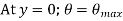
The deflection of beam is defined as the vertical distance between the axis of the beam before and after loading at that point.
It is denoted by y.
Deflection is always zero at the supports.
Slope of Beam
Slope at any point is the angle in radian between the tangent to the elastic curve at that point and the original axis of the beam.
It is denoted by 
|

Boundary Conditions
|


|
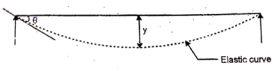
Fig.1 Simply supported beam
b. Cantilever Beam
|


|
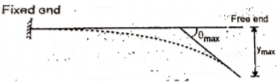
Fig.2 Cantilever beam
Curvature of the Bending Beam
Consider a abeam AB of Span L subjected to a bending moment M.
Let the beam is deflected in a circular arc as shown in figure below.
|
Fig.3 Beam deflected in circular arc
Let, R = Radius of curvature of bent up y = Deflection of beam at center beam
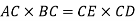
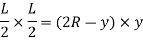
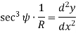
From the geometry of circle,
In practice, deflection of beam ‘y’ is very small and hence its square can be neglected. Therefore,
By using Flexure formula,
Hence,
From the geometry of figure, the slope of the beam at A is also equal to angle AOC
Since,
|


Differential Equation for deflection
Consider an elemental part AB of beam as shown in figure below.
|
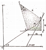
Fig.4 Elemental part AB of beam
Let, Ds = Length of bram AB
R = Radius of bent arc C = Center of arc From the geometry of figure,
And length of arc,
|


Consider  as shown in figure below.
|
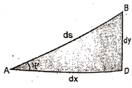
If x and y are coordinate of point A.
Then AD = dx and BD = dy
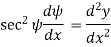
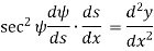
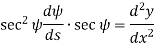
Differentiating above equation we get,
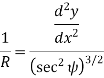
Now we have,
Hence,
|


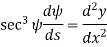


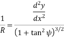
In practice, the slope (dy/dx) at any point of beam is very small, therefore, the square of  is negligible.
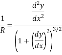
Therefore,
If M is the bending moment which has produced the radius of curvature R, then using bending equation.
Hence, we get,
This is the differential equation of deflection of beam. |


Double Integration Method
Double Integration Method is the very basic method to find the slope and deflection of a beam under load.
In this method a beam is cut into sections and for each section, slope and deflection is found out for critical points.
We have,
Integrating above equation once, we get slope And integrating it again helps to find the deflection y. Procedure to solve problem by Double Integration Method: Step 1: Find the support reactions Step 2: Divide the beam into sections at critical points. Step 3: Find the equation of Moment for each section at a point at distance x from the end point of beam section. Where, M = f(x) Step 4: Use differential equation of deflection to find slope and deflection.
|


Macaulay’s method is similar to double Integration Method.
In this method, bending moment at any section is expressed in the systematically order.
The section x is to be taken in the last portion of the beam.
In this section, bending moment for each force or udl is separated by a compartment lines.
Integrating Bending Moment equation, we will get slope equation.
Again integrating slope equation, we get deflection equation.
For example, consider a beam subjected to loading as shown in fig.
|
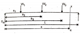
Fig.6 Beam subjected to loading
Step 1: Determine support reactions
Step 2: Consider a section x-x at a distance x covering all the loads from the left end of the beam as shown in figure.
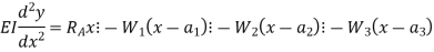
Step 3: Take moment of all force about section x-x, considering sagging BM as a positive and hogging BM as negative
|

Step 4: Use differential equation of deflection
Step 5: Integrating above equation, we get
|

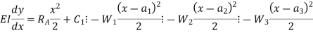
Note: Do not simply the bracket, integrate bracket expression as a whole assuming single term. Write constant of integration C, in first compartment only.
Step 6: Again integration above equation, we get
|

Step 7: The constant of Integration  and
and  is calculated by applying boundary conditions.
Step 8: Substituting the value of constant, in equation obtained in step 5 gives general equation for slope and equation in step 6 gives generate equation for deflection.
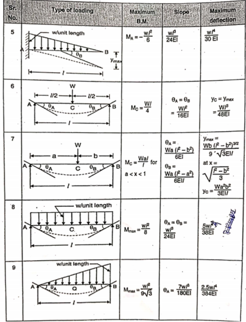
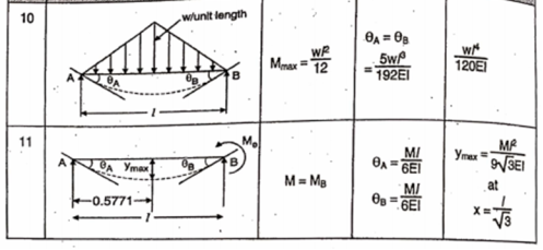
Following is standard formulas for some standard beams with standard loadings:
|
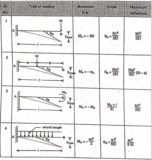
|
|
The moment-area method of finding the deflection of a beam will demand the accurate computation of the area of a moment diagram, as well as the moment of such area about any axis. To pave its way, this section will deal on how to draw moment diagrams by parts and to calculate the moment of such diagrams about a specified axis
Basic principles for moment diagram by parts:
- The bending moment caused by all forces to the left or to the right of any section is equal to the respective algebraic sum of the bending moments at that section caused by each load acting separately.
|
2. The moment of a load about a specified axis is always defined by the equation of a spandrel
|

3. Where n is the degree of power of x.
The graph for the above mentioned equation is
|
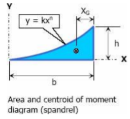
The area and location of centroid is given by
|


Moment-Area Method to find slope and deflection
Moment area method is another method of determining the slopes and deflections in beams. It includes the area of the moment diagram to solve the problem.
|
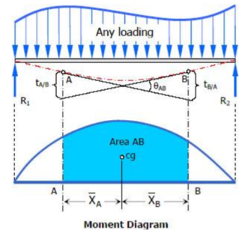
Theorem 1 for Area Moment Method:
The change in slope between the tangents drawn to the elastic curve at any two points A and B is equal to the product of  multiplied by the area of the moment diagram between these two points.
|
Theorem 2 for Area Moment Method:
The deviation of any point B relative to the tangent drawn to the elastic curve at any other point A, in a direction perpendicular to the original position of the beam, is equal to the product of  multiplied by the moment of an area about B of that part of the moment diagram between points A and B.
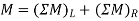
And
|
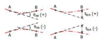
Rules of Sign:
- The deviation at any point is positive if the point lies above the tangent, negative if the point is below the tangent.
- Measured from left tangent, if θ is counterclockwise, the change of slope is positive, negative if θ is clockwise
|
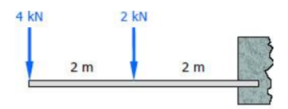
Example 1:
|
Solution:
|
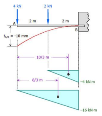
|
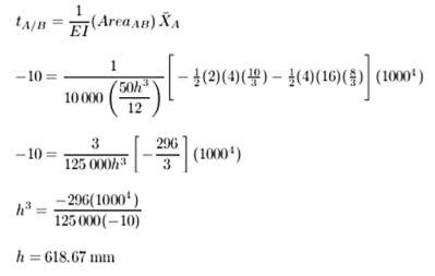
|
Solution:
|
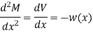
The conjugate beam method is another method for solving the problems on deflections in beams. The relationships between the loading, shear, and bending moments are given by
Where M is the bending moment; V is the shear And w(x) is the intensity of distributed load. Similarly, we have the following
|

If we compare the above two equations, it indicates that if  is loading on an imaginary beam, the resulting shear and moment in the beam are the slope and displacement of the real beam, respectively. This imaginary beam is known as the conjugate beam and its length is same as the original beam.
Conjugate beam method consists of two major steps.
Step 1: Set up an additional beam, known as conjugate beam.
Step 2: Determine the shearing forces and bending moments in the conjugate beam.
The loading diagram showing the elastic loads that are acting on the conjugate beam is nothing but the bending moment diagram of the actual beam and divided by the flexural rigidity EI of the actual beam. If the bending moment is sagging, the elastic load is taken downward.
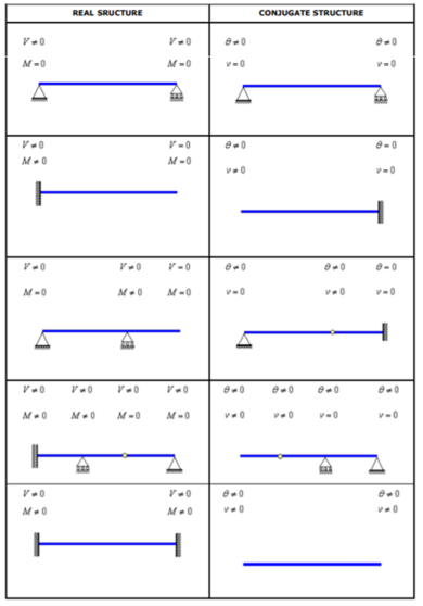
For each existing support condition of the actual beam, there is a corresponding support condition for the conjugate beam. The following table shows the corresponding conjugate beam for different types of actual beams.
|
The actual beam and also the conjugate beam are always in static equilibrium condition.
The slope of the centerline of the actual beam at any cross-section is equal to the shearing force at the corresponding cross-section of the conjugate beam.
This slope is taken positive or in anti-clockwise direction if the shearing force is positive in order to rotate the beam element in anti-clockwise direction in beam convention.
The deflection of the centerline of the actual beam at any point is equal to the bending moment of the corresponding conjugate beam at the corresponding point.
This deflection is taken downward or negative if the bending moment is positive in order to cause top fiber in compression in beam convention.
The positive shearing force and bending moment are shown in the Figure below:
|
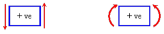
Positive shearing force or bending moment
|
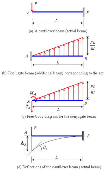
Solution:
The conjugate beam of the actual beam is shown in Figure 4.8(b). A linearly varying distributed upward elastic load with intensity equal to zero at A and equal to PL/EI at B. The free-body diagram for the conjugate beam is shown in Figure 4.8(c). The reactions at A of the conjugate beam are given by
|
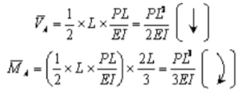
The slope at A,  and the deflection
  at the free end A of the actual beam in Figure (d) are respectively equal to the shearing force
  and the bending moment
  at the fixed end A of the conjugate beam in Figure (d)
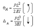
Hence,
|
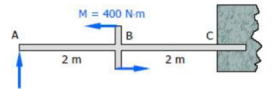
Example 2: Determine the deflection at the free end of the beam shown in Figure below, using conjugate beam method.
|
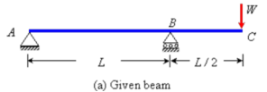
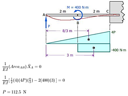
Solution:
The corresponding conjugate beam and loading are shown in Figure (b).
|
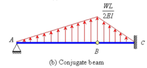
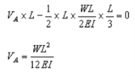
The loading is upward linearly distributed load with maximum value of  at B. Taking moment about point B, the vertical reaction at A in the conjugate beam is given by
|
The bending moment at C (by taking moment about C) is given by
|
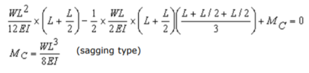
Hence, the deflection of point C will be equal to  in the downward direction.
References
- Strength of Material by S. S. Ratan


