Unit -2
Geodetic Surveying
Triangulation is a surveying method that measures angles in a triangle formed by three survey control points. Using trigonometry and measured length of just one side, the other distances in the triangle are calculated.
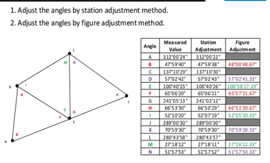
A triangulation figure or triangulation system is a group of triangles, with a single
and common side to preceding and following figures.
System of framework,
The common figures or system used in triangulation system are:
- Single Chain of Triangles
- Double Chain of Triangles
- Central Point Figures
- Quadrilaterals
1. Single Chain of Triangles in Triangulation
Single chain of triangles are used to survey narrow strip of terrain. This figure or system is rapid and economical. The figures made in this method is not so accurate and is not used for primary works. The number of conditions that are used to fulfill figure conditions is relatively small.
In this method, two independent routes cannot be used to determine solution of the triangles. Hence, to reduce accumulation of errors, it is recommended to introduce baseline frequently.
Double chain figures are used for covering larger area.
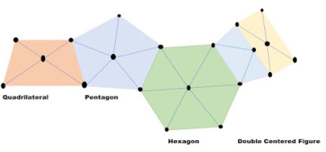
It is used to cover area in a flat country. It provides satisfactory results. The centered figures can be quadrilaterals, hexagons, or pentagons with central stations. The figure provide desired checks during computations. The progress of centered figures work is slow as they require more instrument setting.
The quadrilateral with four corner stations and observed diagonal forms the best figures. It is best suited for hilly country. Since computed length of the sides can be carried through the system by different combinations of sides and angles, system is most accurate.
baseline measurement
Base line is laid down with great accuracy of measurement
It is the alignment asit forms the basis for the computations of triangulation system the length of the base line depends upon the grades of thetriangulation.
Equipment for Baseline Measurements
- Tape
- Straining Device
- Spring balance or weight and pulley
- Thermometers and a finely divided scale
- Marking tripod or station rakes
- Supporting tripods or stakes
base measurement by rigid bar and flexible apparatus,
Methods used to measure Baseline
- Rigid bar method
- Wheeler’s method
- Jaderin’s method
- Hunter’s short base method
- Tacheometric method
|
Choices
Choices of Site selection for baseline
Following factors must be accounted for while selecting the site for baseline
a. Ground should be firm and smooth
b. Two ends of baseline must be intervisible.
c. Site must be free from any obstruction throughout base length.
d. Site should be well shaped triangle can be obtained while connecting it’s and stations to main triangulation station.
e. Site should be such that less length of baseline as specified is available.
f. Site must be level.
g. High undulating ground should be avoided.
Instrument and accessories of baseline
1) Tape
2) Straining device
3) Weight and pulley
4) Thermometer and finely divided scale.
5) Marking tripod or station rakes
6) Supporting tripods
7) Chains
Extension of baseline correction
Chain / Tape corrections
1)Correction due to standardization Correction per chain length
Total correction
True length of line Alternate solution of Q →(1) Core (1) L = 30m andL' = 30.40 m 1) C' = L'-L = 30.40-30 = (+) 0.40m 2) Number of chains = n = 3) Total correction
4) Total length l = 12690+169.20 = 16459.2 |
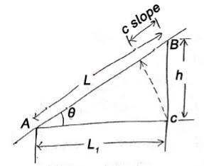
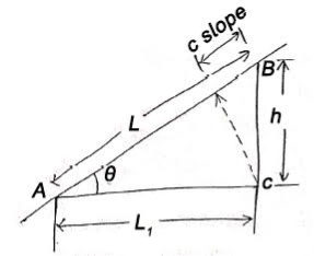
2) Correction due to slope
This correction is always a negative correction. - Correct distance between any two points on ground is horizontal distance. Correction required = L –
If
|
3) Correction due to wrong alignment
Same as slope correction If endpoint of chain is not put on the straight line between points to be measured
Correction is always negative. |
4)Temperature correction If
L = length of chain / tape
|
2) Pull correction
L = length of chain / tape
E = Young's modulus Pull correction =
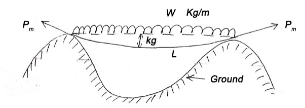
3) Sag correction
This collection is always negative. Formal tension The value of pull For which positive pull correction is exactly equal to negative sag correction is called normal tension.
|
SUBSTANCE BAR
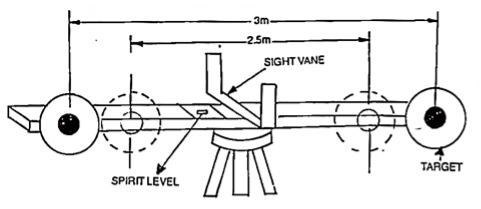
A subtense bar (fig. is a horizontal staff with targets fixed at a known distance apart. It is about 4m long having a small spirit level and a quick levelling head.
A sight rule, provided at its centre, can be placed along line of sight by viewing the telescope of the theodolite thought the vanes. The bar is mounted on a tripod and is placed at right angles to line of sight for making observations. After levelling and aligning, it is clamped by means of clamp screw.
The targets, made of discs of about 20 cm diameter are painted red on one side, and white on the other. The centres of body sides of the targets are painted black in 7.5 cm diameter. The targets are placed at a distance of 2.5 m and 3 m. When targets are placed 2.5 m apart, the white faces are to face instrument and when they are placed 3m apart, the red faces face instrument.
|
The horizontal and vertical angles are measured with a transit theodolite. For measuring vertical angles method will be similarly to the movable hair method of stadia tacheometry and distances are similarly deduced. For measuring horizontal angles, subtended at the instrument station by two targets, method of repetition is used, the horizontal distance.
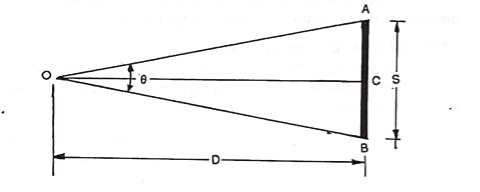
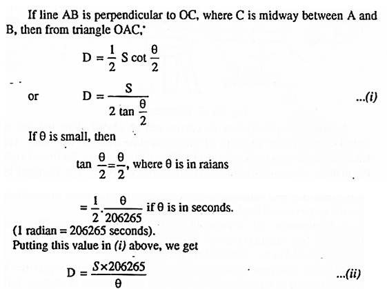
D between the instrument station and the subtense bar station is found as follows:
Let O= the position of the instrument for measuring the horizontal angle 0 by the horizontal circle of theodolite.
AB= horizontal base of a length S.
|
|
- Subtense bars pre-date electronic distance measurement
- It is used when direct taping between points was not possible.
- They were not universally adopted as a primary distance measuring device
- They are included here, not because anyone will use one today, but because they are an interesting way of distance determination.
(1) Geometry
(a) Principle
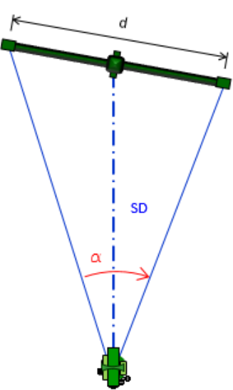
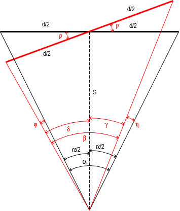
The triangle formed by the subtense bar and instrument is a long narrow isosceles triangle. The angle measured at the instrument is small making for some weak geometry, particularly in long distances.
(b) Behavior
(c) Compensation
(2) Orientation
(a) Principle
Distance determination is predicated on the subtense bar being perpendicular to the line. Most had a sighting system which helped orient the bar correctly
| |
Figure |
(b) Behavior
Misorientation of the bar introduces a systematic error, Figure
| |
Figure |
|
Without knowing the rotation angle and its direction, however, it's impossible compute the corrections. Even if the rotation were known, the horizontal angle corrections would be small. For example, at 100 meters, a 2 meter long bar rotated 10° results in a horizontal angle error of 0°00'07". This would be well inside pointing and setup errors.
(c) Compensation
Experience; Careful equipment set up.
(1) Refraction and Curvature
(a) Principle
The line of sight, on which subtense bar use depends, is bent by the atmosphere and deviates from a level line due to earth curvature. The effect of each increases as does distance. However, the line of sight to each end of the bar deviates the same amount and in the vertical direction so the combined effect does not affect the horizontal angle measurement.
At a distance of 1000 ft (pushing it with a subtense bar) and a 65°00'00" zenith angle (pretty steep), varying the angle 4.9" makes a difference of 0.01 ft horizontal and 0.02 ft vertical, neither of which affects the distances.
For all intents and purposes, curvature and refraction don't affect subtense bar measurements.
(b) Behavior
Systematic but negligible.
(c) Compensation
Not necessary
(2) Atmospheric conditions
(a) Principle
In addition to refraction, local atmospheric anomalies can have varying effect when the line of sight passes near a radiant surface which reflects direct sunlight pr emits absorbed heat. The line of sight in such conditions is not stable which introduces pointing errors.
(b) Behavior
Random
(c) Compensation
Select locations either removed from heat wave sources or limit observations to time of day (early) before the sun heats the intermediate surface or absorption takes place.
(3) Temperature
(a) Principle
Subtense bars are constructed of low thermal expansion alloy materials. They are not affected by temperature changes sufficiently to alter distance measurement within useful operating range.
Temperature is more an instrument operator comfort issue.
(b) Behavior
Systematic but negligible.
(c) Compensation
Not necessary.
(1) Set up
(a) Principle
Both the subtense bar and measuring instrument bust be set up over their respective points. This is more fully discussed in the Electronic Distance Measurement section.
(b) Behavior
Random
(c) Compensation
Careful set ups with practice will minimize the random error.
(2) Pointing
(a) Principle
The surveyor must sight both targets as accurately as possible. Longer distances are increasingly affected as the overall angle between subtense target gets smaller.
(b) Behavior
(c) Compensation
(3) Computations
(a) Behavior
(b) Compensation
Signals: -
- It is small device which is used to define location of triangulation station such that it is easily observed from other stations.
- Signal must be vertical over station.
- It is placed centrally over station mark.
- It is important to place over station mark because accuracy of triangulation system depends on signal that is entering of signal.
Signal:-
1) Opaque signal
2) Luminous signal
a) Opaque signal:-
Is type of signal used where less accuracy and for short sight distance ( i.e. not more than 30 kilometer)
It must be used in day time only.
Cheaper than luminous signal.
Example of opaque signal
(i)Target signal – suitable for distance upto 30 km
(ii) Pole signal- distance up to 6 km
(iii) Elevated signal – elevated tower are used as signal and suitable for distance upto 30 to 40 km.
(iv)Stone signpost
(v)Pole and brush signal
b)Luminous signal:-
This type of signal basically used for geodetic survey because of quite distinct and have clear visibility even for long distance (more than 30 km).
It is used for day as well as night also.
Luminous signal
-Sun signal
-Light signal
(i) Sun signal - also known as heliotrope. Heliotrope reflect sun rays towards station.
(ii) Night signals - observation is at night. Eg. Drummond's light and magnesium lamp with parabolic reflector
Satellite station
It is also known as eccentric station.
Satellite station is a false station because it is not possible to set the instrument over the structure false station point is assumed.
It is also a place where movement of satellite is followed and receive information from them.
Reduction to centre
It is defined as the process of computing the correct angle from observed angle is called reduction to centre.
Triangulation network:-
It is a network of of triangles used to find the distance and position of point.
Network is done by measuring length of one side of a triangle and reducing its angle and length of other two sides by observation from baseline.
Reference Books:
1. Principles of Surveying. Vol. I by J. G. Olliver, J. Clendinning - Van Nostrand
Reinhold.
2. Plane Surveying by A. M. Chandra, New Age International Publishers.
3. Surveying Vol. I & II by Dr. K. R. Arora, Standard Book House.
4. Elements of Photogrammetry - Paul R. Wolf, McGraw Hill Publication.
5. Remote sensing and Geographical Information System- A. M. Chandra and S. K.
Ghosh, Narosa Publishing House.
6. Advanced Surveying -Total Station, GIS and Remote Sensing – Satheesh Gopi, R.
Sathikumar and N. Madhu, Pearson publication.
7. The GIS Book, 5Th Edition, George B. Korte, PE onwards press.
