Introduction and principle of EDM: -
EDM is electronic distance measurement survey which is used to find the distance of two point or object. This techniques provide precise and more faster surveying than the old and conventional instruments that are used earlier. In old and conventional surveying, in linear measurement,chain and tape are used while in angular measurements compass are used, Dumpy level and a leveling staff are used in work of leveling. With this instruments, survey work become tedious
Hence in this case,the modern surveying instruments are used and this techniques are replacing the old surveying instruments such as Dumpy level ,chain,tape and compass. With the help of this modern techniques, survey work will be more , faster and precise.
Electronic distance measurement is the way of finding the length between two points by using electronic energy waves by taking the time and velocity.
planks gives the principle in which electromagnetic radiation travel with speed of light and time travel by waves can be noted which colloids with target .and hence distance can be find out by the below given formula:-
distance = velocity of light X travel time
Modulation:-
Distance measurement in EDM and in modern surveying are done electronically. Distance is taken as the function of the speed of light, elapsed time and frequency of electromagnetic.
Frequency occur in electronic distance measuring device (EDM) can be used to find the elapsed travel time of its signal, because the signal reflect or bounce off a reflector and returns to origin point where it started.
EDM needs one oscillator at the origin, as the electromagnetic wave travels to a retroprism and reflected back to its origin. Both transmitter and the receiver of the signal are used. the instrument can take half the time elapsed between the moment of transmission and the moment of reception, multiply by the speed of light,it give the distance between the object and origin point.
The elements for the calculation of the distance measured by an EDM, then take
ρ are the time elapsed between transmission and reception of the signal, Δt, and the speed of light, c.
Distance = ρ, Elapsed Time = Δt, Rate = c
Distance = Elapsed Time x Rate
Types of Electronic Distance Measurement Instrument:-
The following are the instrument which are used in EDM as carrier wave:-
- Microwave instruments
- Infrared wave instruments
- Light wave instruments.
- Microwave Instruments - other name is tellurometers, microwaves are used in this instrument.
- Infrared Wave Instruments – it Uses prism reflectors that pick up amplitude modulated infrared waves.
- Visible Light Wave Instruments – it Uses modulated light waves to find out the specific range.
Microwaves are used in this instrument.In 1950 in South Africa by Dr. T.L. Wadley and named later as Tellurometers.. The range of these instruments is up to 100 km. 12 to 24 V batteries are required in this instrument ,That’s why light and portable. This instrument can be used in both day and night time.
It consists of two identical units.
1.master unit and
2.remote unit.
pressing a button in insturment, master unit can be converted into a remote unit and viceversa. It requires two skilled persons to operate.
These instruments is useful for the most of the civil works.In this instrument amplitude modulated infrared waves are used. The range of these instruments is up to 3 km. Prism reflectors is used at the end to find the line to be measured.
accuracy upto ± 10 mm is achieved in this instrument.These instrument is economical and can be mounted on theodolite
DISTOMAT DI 1000 and DISTOMAT DI 55 are the name of instrument used as infrared wave instrument.
Total Station:-
A total station is an electronic/optical instrument used in modern surveying and building construction that uses electronic transit theodolite in conjunction with electronic distance meter (EDM).It is also integrated with microprocessor, electronic data collector and storage system.
The instrument is used to measure sloping distance of object to the instrument, horizontal angles and vertical angles. This Microprocessor unit enables for computation of data collected to further calculate the horizontal distance, coordinates of a point and reduced level of point.
Data collected from total station can be downloaded into computer/laptops for further processing of information.
Total stations are mainly used by land surveyors and civil engineers, either to record features as in topographic surveying or to set osut features (such as roads, houses or boundaries). They are also used by archaeologists to record excavations and by police, crime scene investigators, private accident Reconstructionist and insurance companies to take measurements of scenes.
- Missing line measurement (MLM}
- Control Survey (Traverse).
- Archaeologists use total station to record excavations and its details
- Height measurement (Remove elevation measurement- REM).
- Resection are easy by total station.
- Remote Distance Measurement (RDM)
- General purpose of angle and distance measurement
- detailed maps
Total Station are use in following areas:-
- Road Survey
- Rail Survey
- Canal Survey
- Mine Survey
- Engineering Survey
- Large Scale Survey
Parts of a Total Station
There are mainly four main components which are
- EDM (Electronic Distance Measurement),
- electronic theodolite,
- microprocessor and
- electronic display
Accessories of Total Station
Accessories of total station are as follows:-
- Total Station Battery & Charger,
- Total Station Prism,
- Total Station Tripod & Bipod,
- Total Station Prism Pole and
- Stand For Total Station.
Advantages of Using Total Stations:-
- Field work is very fast as compared to conventional survey.
- Calculation is also fast and accurate.
- Accuracy is very high.
- Manual errors can be eliminated.
- Computers can used for map making and contour and its cross-sections
Applications of Total Station:-
the following application of total station are as given below:-
- Detail survey is carried out easily by this technique.
- Missing Line Measurement (MLM)
- Plotting of contours
- Carrying out controlled surveys
- Used to fix the missing pillars and column.
- Area calculations
Field Procedure for Total Station
Basic Steps involved in Total station surveying
Step-1: Setting up the of the instrument along with the tripod
Step-2: Levelling of the instrument approximately with the help of “bull’s eye bubble” and then verifying the levelling electronically
Step-3: Adjustment of reticle focus and image.
Step-4: Recording all the measurements
Step-5: Data Processing
Step 1: Tripod Setup Tripod legs should be equally spacedTripod head should be approximately levelHead should be directly over survey point
Step 2: Mount Instrument on TripodPlace Instrument on Tripod Secure with centering screw while bracing the instrument with the other hand Insert battery in instrument before leveling
Step 3: Focus on Survey PointFocus the optical plummet on the survey point
Step 4: Leveling the InstrumentAdjust the leveling foot screws to center the survey point in the optical plummet reticle Center the bubble in the circular level by adjusting the tripod legs
Step 4: Leveling ... Loosen the horizontal clamp and turn instrument until plate level is parallel to 2 of the leveling foot screws Center the bubble using the leveling screws- the bubble moves toward the screw that is turned clockwiseRotate the instrument 90 degrees and level using the 3rd leveling screw
Step 4: Leveling ... Observe the survey point in the optical plummet and center the point by loosening the centering screw and sliding the entire instrumentAfter re-tightening the centering screw check to make sure the plate level bubble is level in several directions
Step 5: Turn on the instrument by pressing and holding the “on” button The opening screen will be the “MEAS” screen. Select the Tilt function and then adjust the foot level screws to exactly center the electronic “bubble
Total Station Errors:-
50
1 CALIBRATION OF TOTAL STATIONS
Maintaining the high level of accuracy offered by modern total stations, there is much more emphasis on monitoring instrumental errors, and some construction sites require all instruments to be checked regularly using procedures outlined in the quality manuals.
Some instrumental errors can be eliminated by observing on two faces of the total station and averaging, but because one face measurements is the preferred method on site, it is important to determine the amount of instrumental errors and correct for them.
For total stations, instrumental errors are measured and corrected by electronic calibration procedures that are carried out at any time and are applied to the instrument on site.
Since calibration parameters can change due to mechanical shock, temperature changes and rough handling of high-precision instrument, an electronic calibration should be carried out on a total station as follows:
- Before using the instrument for the first time
- After long storage periods
- After rough or long transportation
- After long periods of work
- Following big changes in temperature
- Regularly for precision surveys
Before every calibration, it is essential to allow the total station enough to reach the ambient temperature.
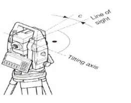
2. HORIZONTAL COLLIMATION (OR LINE OF SIGHT ERROR)
This axial error happens when the line of sight is not perpendicular to the tilting axis. It affects all horizontal circle readings and increases parallel to steep sightings, but this is eliminated by observing on two faces. For single face measurements,
an on-board calibration function is used to determine c, the deviation between the actual line of sight and a line perpendicular to the tilting axis. A correction will be applied automatically for this to all horizontal circle readings.
|
3 TILTING AXIS ERROR
axial errors occur when the titling axis of the total station is not perpendicular to its vertical axis, this has no effect on sightings taken when the telescope is horizontal, but produces errors into horizontal circle readings when the telescope is tilted, especially for steep sightings.
But with horizontal collimation error, this error is erased by two face measurements, or the tilting axis error (a) is measured in a calibration procedure and a correction applied for this to all horizontal circle readings.
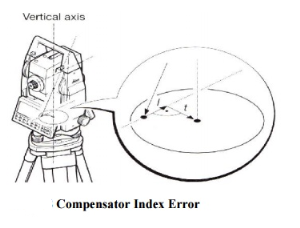
4 COMPENSATOR INDEX ERROR
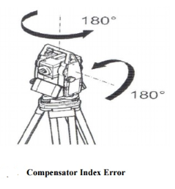
Errors that were caused by not levelling a theodolite or total station carefully cannot be eliminated by taking face left and face right readings. If the total station is fitted with a compensator it will measure residual tilts of the instrument and will apply corrections to the horizontal and vertical angles for these.
All compensators will have a longitudinal error l and traverse error t known as zero point errors which are averaged using face left and face right readings but for single face readings must be determined by the calibration function of the total station.
|
A vertical collimation error exists on a total station if the 0o to 180o line in the vertical circle does not coincide with its vertical axis and this zero point error is present in all vertical circle readings and like the horizontal collimation error, it is eliminated by taking FL and FR readings or by determining i
Any difference between the measured horizontal and vertical angles is then identified as an instrumental error and applied to all readings. The total station is thus calibrated and the procedure is the same for all of the error type.
|
GPS(Global Positioning System)
GPS is a navigation system using satellites, a receiver and algorithms to synchronize location, velocity and time data for air, sea and land travel.
GPS Satellite Constellation
The satellite constellation consists of 24-satellite constellation. The satellites are placed in six Earth centered orbital planes with four satellites in each plane. The nominal orbital period of a GPS satellite is one-half of a side realday. The orbits are circular and equally spaced about the equator at a 60°separation with an inclination relative to the equator of nominally 55°. The orbital radius (i.e., nominal distance from the center of mass of the Earth to the satellite) is approximately 26,600km.
GPS Accessories:
- GPS Cables & Antennas,
- GPS Cases,
- GPS Chargers & Adapters,
- GPS Maps,
- GPS Mounts
Segments
GPS is made up of three different components, called as segments:
The three segments of GPS are:
- Space (Satellites) —satellites circling the Earth, transmitting signals to users on geographical position and time of day.
- Ground control —Control Segment is made up of Earth-based monitor stations, master control stations and ground antenna.It include tracking and operating the satellites in space and monitoring transmissions.
- User equipment — GPS receivers and transmitters including items like watches, smartphones etc
Satellite and receiver clock errors
Each GPS Block II and Block IIA satellite contains four atomic clocks, two cesium and two rubidium. The newer generation Block IIR satellites carry rubidium clocks only. One of the onboard clocks, a cesium for Block II and IIA, is selected to provide the frequency and the timing requirements for generating the GPS signals.
OCS Operations
The MCS is the center of the control segment operations and is found at Falcon Air Force Base,Colorado Springs, CO. The monitor stations inactively track the GPS satellites as they pass overhead by making pseudorange and delta range measurements. These measurements are made using both the L1 and L2 GPS satellite downlink frequencies. This raw data and the received navigation message with local weather is transmitted to the MCS through the Defense Satellite Communications System and other ground communications systems.
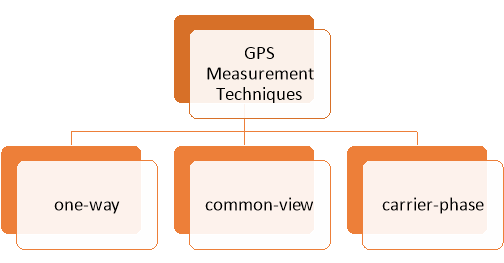
GPS Measurement Techniques:-
- there are many different types of GPS measurements used in time and frequency metrology.
- These measurements can be divided into three generalcategories: one-way, common-view, and carrier-phase.
- normally GPS measurements made in calibration and testing laboratories are one-way measurements.
|
- In GPS measurement techniques -One-way measurements are easy to make and their uncertainties are small enough to meet the requirements calibration and testing laboratory.
Common-view and carrier-phase measurements require more effort in processing of the measurement data. For this reason, they are usually used for small as possible.
1-Way GPS Measurements:-
- one-way GPS technique measurement use the signals obtained from receiver of GPS as the reference for calibration.
- GPS signals are used in real time, and no post processing of the measurement results is required.
- The purpose of the measurement is usually either to synchronize a non-time pulse, or to calibrate frequency source.
Errors and Biases
Multipath is a error source for both the carrier-phase and pseu-dorange measurements. Multipath error occurs if the GPS signal arrives at the receiver antenna through different paths. These paths can be the direct line of sight signal and reflected signals from objects surrounding the receiver antenna.
Multipath distorts the original signal by interference with the reflected signals at the GPS antenna. It affects both the carrier phase and pseudorange measurements whereas its size is much larger in the pseu-dorange measurements.
GPS ephemeris errors
Satellite positions as a function of time, which where included in the broadcast satellite navigation message and are predicted from previous GPS observations at the ground control stations. Overlapping 4-hour GPS data spans are used by the operational control system to predict fresh satellite orbital elements for each 1-hour period.
Surveying with GPS:-
- Now a days GPS is part of everyday life.
- The following things were the GPS is used are as follows
- mobile phones,
- navigation in car
- rescue and search equipment.
- GPS was rapidly using for surveying, as it can give direct position of Latitude, Longitude and Height , without measureing angles and distances between 2 points or intermediate points.
- clear view of the sky is required so the signal from the GPS satellites could received clearly.
Accuracy considerations
Some factors that can hinder GPS accuracy inculde :-
- Atmospheric effects: heavy storm cover and solar storms can all affect GPS devices.
- Numerical miscalculations: This might be a factor when the device hardware is not designed to specifications.
- Artificial interference: These include GPS spoofs
- Physical obstructions: Arrival time measurements can be skewed by large masses like mountains, buildings, trees and more.
- The feature set of a GNSS device
- The position of the satellites at the time the recording was made
- The characteristics of the surrounding landscape
It is a collection of computer software and information which is used for viewing, analysing, managing and displaying geographical data.
presenting data in simple visual ways.
The three types of GIS Data are
-spatial,
–attribute, &
—metadata
- Spatial Data
- vector data
- Point Data — layers containing by points (or “events”) described by x,y (lat,long; easting, northing)
- Line/Polyline Data — layers that are described by x,y points (nodes, events) and lines (arcs) between points (line segments and polylines)
- Polygon Data — layers of closed line segments enclosing areas that are described by attributes
- vector data
iv. |
iv. Polygon data can be “multipart” like the islands of the state of Hawaii.
B. raster or grid data (matrices of numbers describing e.g., elevation, population, herbicide use, etc.
C. images or pictures such as remote sensing data or scans of maps or other photos. This is special “grid” where the number in each cell describes what color to paint or the spectral character of the image in that cell. (to be used, the “picture” must be placed on a coordinate system, or “rectified” or “georeferenced”)
D. TINs – Triangular Irregular Networks – used to discretize continuous data
E. Terrain datasets built from lidar and other point clouds.Demo in ArcGIS
2. Attribute data are non-spatial characteristics that are connected by tables to points, lines, “events” on lines, and polygons (and in some cases GRID cells)
- A point, vector or raster geologic map might describe a “rock unit” on a map with a single number, letter or name, but the associated attribute table might have
- age
- lithology
- percent quartz
- etc, for each rock type on the map.
- most GIS programs can either plot the polygon by the identifier or by one of the attributes
3. Metadata
- metadata are the most forgotten data type
- absolutely necessary if you’re going to use data, or if someone is going to use your data later (or your derivative information)
- contains information about
- scale
- accuracy
- projection/datum
- data source
- manipulations
- how to acquire data
More specifically, GIS is used through:
- Environmental Geography – to analyse the impact people have on the environment.
- Physical Geography – to study the elements of atmosphere, biosphere and geosphere.
- Emergency Management Information System – to give real time data to emergency responders about the geographical layout.
- Health Geography – to use geographical information to study health related issues such as disease and illness.
- Economic Geography – to study economic activities across the earth.
- Transportation Geography – to investigate the spatial interactions of people or things.
Topographic map
This is the first step of the Engineering survey, using a topographic map of the area under consideration, which can be availed from the Survey of India, we can propose different alternatives of the road alignment.
This topographic map in general have a contour interval of around 30 m to 40 m.
Reconnaissance Survey: it is the second phase where survey team is headed to the area under study with the minor surveying instruments like Abney level, Tangent Clinometer etc. to do a rough survey of the area under study.
The rough survey is done along the alternatives proposed in the map study and feasibility of the road alignment is checked along the different routes. Some of the routes may be cancelled out or they may be changed if they appear to impossible in this study. So finally they will have a set of routes which are to be further studies in the next step.
Preliminary Survey: In this step the alternative routes which are proposed after a rough survey in the second step are surveyed in details using some advanced instruments like levels, chain and theodolite. Aerial Photogrammetry is best suited for this type of survey.
All the necessary details to carry out the comparative study of the different routes are collected and then finally we have to decide one alignment best suited for the alignment of the road.
Detailed Survey: In this part we have carry out the detailed study of the final route using some very precise instruments like Theodolite and Chain to gather all the necessary data for the final estimation, design and preparing drawings using which the construction can be started. A detailed project report is to be prepared and all the necessary data is collected to prepare that report.
So, the profiling, cross-sectioning and soil investigation are carried out very precisely. CBR values are also found to find out the design thickness of the pavement. After collecting the data a final drawing a report is prepared which concludes the highway planning part.
Reference Books:
1. Principles of Surveying. Vol. I by J. G. Olliver, J. Clendinning - Van Nostrand
Reinhold.
2. Plane Surveying by A. M. Chandra, New Age International Publishers.
3. Surveying Vol. I & II by Dr. K. R. Arora, Standard Book House.
4. Elements of Photogrammetry - Paul R. Wolf, McGraw Hill Publication.
5. Remote sensing and Geographical Information System- A. M. Chandra and S. K.
Ghosh, Narosa Publishing House.
6. Advanced Surveying -Total Station, GIS and Remote Sensing – Satheesh Gopi, R.
Sathikumar and N. Madhu, Pearson publication.
7. The GIS Book, 5Th Edition, George B. Korte, PE onwards press.


