Unit -4
Curves
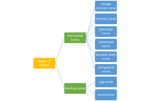
Curves –
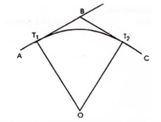
When two straight lines intersect at some angle then a curve is provided in between them which meets the straight line tangentially.
Curve are in fact Arc with some definite radius and center that is they are a part of circle. it is due to the curves only that the change in direction is made possible a very smooth task
Necessity (Curves are provided for following reasons)
- Curves are needed on highways Railways and Canal for bringing about gradual change of direction of motion
- to bring about gradual changes in direction of motion
- to connect important places
- to avoid obstructions
- to bring about gradual changes in grade and for good visibility
- to balance earthquake in acceleration cutting
- minimizing construction cost
Designation of curves
A curve may be designated either by the
- radius or
- angle (in degrees) subtended at the center by a chord of 30 meters (100 ft.) length.
Relation between degree and radius of curve.
Arc definition / Chord Definition: -
Arc definition of degree of curve: According to this, degree of curve in the central angle subtended by an arc of length of 20m or 30 m. If R = radius of curve D = degree of curve as per arc definition for 30m arc length. D° = Q (radians) =
For 20 mm length
|
|
Simple curves
|
- simple curve consists of a single arc of a circle connecting two straights.
- It consists radius of the same magnitude throughout.
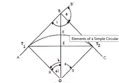
- T1 D T2 is the simple curve with T1O as its radius
Elements,
|
|
Compound curves
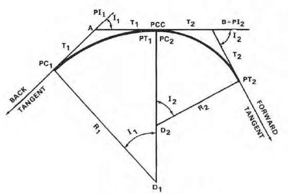
Compound curve is a combination of curves of two or more radii.
Elements
Compound curve has seven elements
- Radius R1,
- Radius R2,
- deflection angle φ,
- deflection angle of the first arc φ1,
- deflection angle of the second arc φ2,
- tangent length LT1 and LT2.
Elements of Compound Curves
∆ = ∆ 1 + ∆ 2
Length of the main tangents IT1 and IT2:
|
Design of compound curves
Compound Curve between Successive PIs
The calculations and procedure for laying out a compound curve between successive PIs are outlined in the following steps. This procedure is illustrated in figure 11a.
|
- Find out the PI of the first curve at point A from field data or last computations.
- make I1, I2, and distance AB from the field data.
- Find the value of D1, the D for the first curve.
- Compute R1, the radius of the first curve
- find T1, the tangent of the first curve.
T1 = R1(Tan ½ I) - find T2, the tangent of the 2ndcurve.
T2 = AB – T1 - findR2, the radius of the 2nd curve.
R2 = T2 / Tan ½ I - findD2 for the second curve.
- Compare D1 and D2. They should not differ by more than 3 degrees, if not then check again
- If the two Ds are fine, then compute the remaining data and deflection angles for the first curve.
- Compute the PI of the second curve. Since the PCC is at the same station as the PT of the first curve, then PI2 = PT1 + T2.
- Compute the remaining data and deflection angles for the second curve, and lay in the curves.
Compound Curve between Successive Tangents.
Place the instrument at the PI and sight along the back tangent.
- Lay out a distance AC from the PI along the back tangent, and set PI1.
- See the back tangent from PI2 a distance T1, and set PC1.
- Sight along the forward tangent with the instrument still at the PI.
- Lay out a distance BC from the PI along the forward tangent, and set PI2.
- see along the forward tangent from PI a distance T2, and set PT2.
- Check the location of PI1 and PI2 by either measuring the distance between the two PIs and comparing the measured distance to the computed length of line AB, or by placing the instrument at PI1, sighting the PI, and laying off I1. The resulting line-of-sight should meet PI2.
Design procedure of compound curves
Step 1 : Locate tangent point T, by measuring back the total tangent length (Tt) along back tangent, from the point of intersection V.
Likewise, locate the tangent point T' by measuring along forward tangent the distance Tt from V.
Setting out of transition curve :
Step 2 : Set a theodolite over the point T. Set vernier A to zero, and clamp the upper plate.
Step 3 : Direct the line of sight of theodolite to intersection point V, and clamp lower plate.
Step 4 : Release upper plate. Set the vernier A to first deflection angle (a1).
The line of sight now points towards the first peg on transition curve.
Step 5 : With the zero of the tape pinned at T and an arrow kept at mark corresponding to the first length of the chord, assistant will swing the tape till the arrow is bisected by line of sight.
Fix the first peg at arrow point.
Step 6 : Set the vernier A on the second deflection angle (a2) to direct line of sight to the second peg.
Step 7 : With zero of the tape pinned at T, and keeping an arrow at mark corresponding to the total length of the first and second chords, assistant will swing an arc till the arrow is bisected by the line of sight.
Fix the second peg at arrow point. It should be remembered that the distance is measured from the point T and not from proceeding point.
Step 8 : repeat steps (6) and (7) till the last point C on transition curve is reached.
Setting out of the circular curve :
Step 9 : For setting out circular curve CC', shift the theodolite to junction point C.
Orient theodolite with reference to the common tangent CC1 by directing line of sight towards CT with vernier. A set at a reading equal to , and swinging the telescope clockwise in azimuth by fs(Figure 39.4).
Now line of sight is directed along the common tangent CC1 and the vernier reads zero.
Step 10 : Plunge telescope. The line of sight is now directed along the tangent C1C produced.
deflection angles D1, D2, etc. have been calculated with reference to the tangent C1C produced at C (Figure 38.2).
The line of sight is now correctly oriented, and reading of the vernier A is zero.
Step 11 : Set the vernier A to first deflection angle D1, and locate the first peg on circular curve at a distance of c' from C, where c' is length of the first sub-chord.
Step 12 : Likewise, locate the second peg on circular curve at the distance c equal to the normal chord from first peg with the deflection angle D2 at C.
Step 13 : Continue the above process till junction point C' is reached.
Step 14 : Set out the transition curve T'C' from T' using same procedure as that for transition curve TC.
Setting out of compound curves
Setting a compound curve
- Calculate all elements ∆1 , ∆2, ∆, R1, R2, IT2 and IT1.
- Locate PI (I), PC (T1) and PT (T2)
- Calculate chainage of T1 (chainage of I – tangent length IT1)
- Calculate chainage of the point of compound curvature D.
- Chainage of D = Chainage of T1 + length of arc T1D = chainage of T1 + ΠR1 ∆1 / 180o
- Calculate chainage of T2 = chainage of D + ΠR2 ∆2 / 180o
- Calculate the deflection angles for both the arcs from their tangents, e.g. ∆1 = δ1 = 1719 C1 / R, where C1 is the chord length and R is the radius
Length of curve and other relation
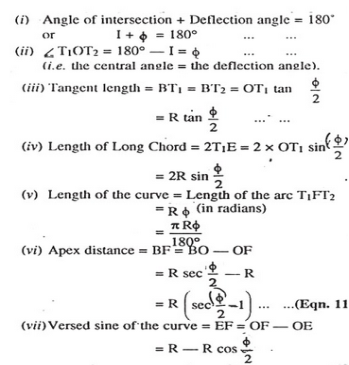
Formula for elements of a simple circular curve
a) Relation between degree and radius of curve.
Arc definition / Chord Definition: -
Arc definition of degree of curve: According to this, degree of curve in the central angle subtended by an arc of length of 20m or 30 m. If R = radius of curve D = degree of curve as per arc definition for 30m arc length. D° = Q (radians) =
For 20 mm length
(b) length of curve
If a 30m arc or chord definition is used
If a 20 m arc orchard definition is used.
(c) Length of tangent: - Tangent length (T) = (d) long chord length Length of long chord (L) From
(e) Apex distance: -
(f) Mid ordinate: -
|
Transition curve
- It is a curve introduced between a simple circular curve industry tour between two simple circular curves.
- Also known as easement curve.
- Its videos, gradually changing from a finite to infinite value or vice versa.
- It is generally used in highway and Railway.
Length of transition curve: -
a) Method of arbitrary gradient: - e = total super elevation provided at junction of transition curve with circular curve L = ne Where rate of super elevation is ∆ in n
(b) Method of Time rate: -
Method of rate of change of radial acceleration
t is the time attained by radial acceleration (a) a =
|
Super elevation or Cant:
It is defined as the raising of outer end of a road or outer rail over inner one. h = super elevation = e w = weight of vehicle P = centrifugal force g = acceleration due to gravity R = radius of curve G = gauge distance between rails u = speed of vehicle B = width of pavement
h = super elevation = e w = weight of vehicle P = centrifugal force g = acceleration due to gravity R = radius of curve G = gauge distance between rails u = speed of vehicle B = width of pavement
|
Method of setting out curve
Linear method (i) Offset from long chord
Where
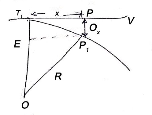
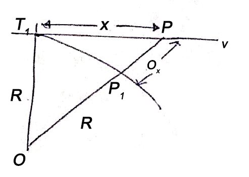
(ii) Perpendicular offset from tangent
(iii) Radial offset from tangent:
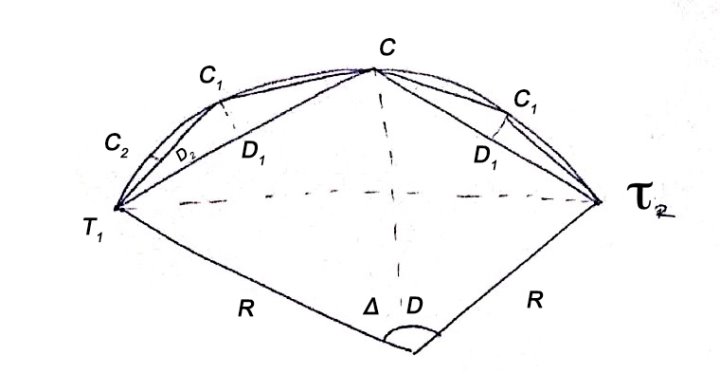
(iv) Successive Bisection of Arc or chord
(v) By offset from chord produced
|
b) Angular method
i) Rankine's method of deflection angle
- It is generally used for setting out a circular curve of long length and large radius.
- It give good result except then chords are long as compared to radius, so that variation between length of an Arc and its cord becomes considerable.
- It is used in highway and Railway

 = Tangential angle
C = chord length
(ii) Tachometric method
-It is similar to Rankine’s method of deflection angle.
- The theodolite at  may be used as Tacheometric and Tacheometric observation are made.
- Less accurate as compared to Rankins.
- Chaining is completely dispersed in this method.

(For Incline and line of sight)

(For horizontal line of sight)
i) Two theodolite method
- Convenient than any of to our method when ground is undulating rough and not suitable for Linear measurements.
- Two theodolite are used and linear measurement are completely eliminated.
- Hence, most accurate method.
- It is based on principle that angle between the tangent and chord is equal to angle subtended by chord in opposite segment.
- Time consuming method
- Most accurate method
- Highly expensive.
Vertical curves
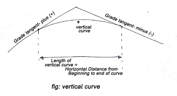
These are curves in a vertical plane, used to join two intersecting grade lines.
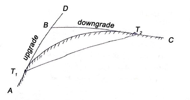
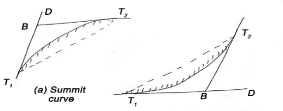
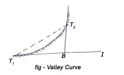
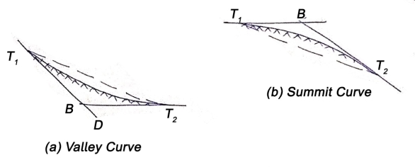
A vertical summit curve is provided when a rising grade join a falling grade and a vertical curve is provided when a falling grade joins a rising grade.
|
|
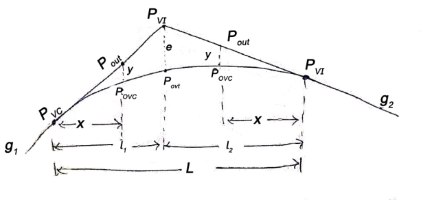
PVC – point of vertical curvature place where curve begins
PVT – point of vertical tangency, where curve end.
PVI – point of vertical intersection, where grade tangents intersect.
POVC - point on vertical curve applies to any point on parabola
POVT - point on vertical tangent, applies to any point on other tangent
(a) Length of vertical curve L = algebraic difference of two grades/ rate of change of grade
(b) Change of end of curve PVT = change of intersection point + half the length
|
Types of vertical curves i) Upgrade followed by a downgrade
ii) Upgrade followed by another upgrade
iii) A downgrade followed by an upgrade
iv) A downgrade followed by an another downgrade
|
Reference Books:
1. Principles of Surveying. Vol. I by J. G. Olliver, J. Clendinning - Van Nostrand
Reinhold.
2. Plane Surveying by A. M. Chandra, New Age International Publishers.
3. Surveying Vol. I & II by Dr. K. R. Arora, Standard Book House.
4. Elements of Photogrammetry - Paul R. Wolf, McGraw Hill Publication.
5. Remote sensing and Geographical Information System- A. M. Chandra and S. K.
Ghosh, Narosa Publishing House.
6. Advanced Surveying -Total Station, GIS and Remote Sensing – Satheesh Gopi, R.Sathikumar and N. Madhu, Pearson publication.
7.The GIS Book, 5Th Edition, George B. Korte, PE onwards press.


