Unit -5
Photogrammetry
Introduction to Photogrammetry Surveying
Photogrammetry is a mapping and surveying procedure or technique, which has many applications in Transportation Department.
Applications of Photogrammetry are as follows: -
- surveying includes site planning,
- data collection of DEM (digital elevation models)
- image-based mapping which is known as orthophotography
- topographic mapping,
- and earthwork volume estimation for roads
The term “photogrammetry” is made of by two words, which is “photo”, and “meter” means measurements from photographs.
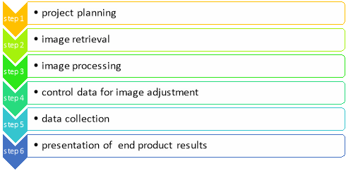
The photogrammetric process consists of following phases: -
|
BASIC CONCEPT: -
The basic or fundamental principle used by photogrammetry is the triangulation. Clicking photograph from at least 2 different areas, so-known “lines of sight” can be developed from each camera to points on the object. This LOS(lines of sight) are mathematically crossed or intersected to made the 3-D coordinates of the points of interest.
Parallax
The movement or displacement of an object caused by a change in the point of observation is known Parallax. By taking photographs of the same object but from the different point is Stereoscopic parallax. aircraft’s motion causes the Change in position of image from one photo to the other or next.
aspects of stereoscopic parallax are as follows: -
- Parallax of any point is directly related to the height of that point
- Parallax is higher for high points as compared to low points
Types of photogrammetry
- Aerial Photogrammetry
- The camera is mounted in an aircraft, usually pointed perpendicular towards the ground with the camera axis vertical or nearly so.
- Many photographs are taken with the clincher – built concept. Later the processing of these photographs done using stereo-plotter.
- Photos are also being used in for Digital Elevation Model (DEM) creation.
- Terrestrial Photogrammetry
- Photographs are taken from a stable, usually known as, position on or near the ground and with the camera axis horizontal or nearly so.
- The position and orientation of the camera are frequently measured directly at the time of exposure. Instrument used for exposing such photograph is known photo theodolite.
- Space Photogrammetry
- In this typoe of photogrammetry, satellites are used.
- Global coverage of satellite image is taken in lesser time with a high-resolution data.
- Interpretative Photogrammetry
- Images are studied and identification is done for judging their significance with standard and careful analysis.
Characteristics: -
An aerial photograph is a central projection, in which the bundles of perspective rays meet at a point of origin known perspective centre. A map is an orthogonal projection, where every point on the ground is projected perpoendicular on to the map on a reduced scale. One of the greatest advantage of central projectionis its ability to produce a three dimensional model of the terrain under the stereoscopes.
1.Fiducial marks:
Fiducial marks are marks built into aerial cameras which can be seen on the sides or in the corners of the photo (or both), and which are used to determine the position of the principal point.
2.Fiducial axes:
lines joining the fronting fiducial marks on a photograph are known fiducial axes.
3.Principal point:
It is a point where the perpendicular projected through the center of the lens meets the photo image.
4. Conjugate principal point:
It is the principal point of an aerial photograph represented on adjacent aerial photograph.
Principal point (PP) and conjugate principal point (CPP)
5. Nadirpoint:
It is a point vertically below camera centre or aircraft.
6.Isocentre:
The point on an air photo which lies midway between the Principal Point and t Nadir point. On a true vertical aerial photograph all these three would be at the same point. There is no such thing as a true vertical aerial photo. Each and every air photo have some degree of tip or tilt.
7.Air base (B):
line joining two air stations is known as Air base.
8.Photobase (b):
air base is known photobase on aerial photograph and it is the interval between the principal point of one photograph and conjugate principal point of adjacent photograph.
9.Forward overlap/Endlap:
The quantity of overlap in the middle of successive photos in a flight line to allow for stereo viewing (usually 60 –70%).
10.Sidelap/Lateral overlap:
The amount of overlap in the middle of air photos in adjacent flight lines (usually 20 –30%).
11.Tilt: I
it is the angle in between the camera axis and vertical. It is also known as rotation of the camera away from the vertical, about the x-or y-axis.
12.Focal length (f):
Distance from the optical centre of the lens to the focal plane.
13.Flying height/altitude (H):
It is a perpendicular distance of aircraft above the datum (usually mean sea level) during flight. It is measured using an instrument known Altimeter mounted in an aircraft.
14.Scale of aerial photograph:
Scale of aerial photograph is known as the ratio of photo distance to the corresponding ground distance.
Terrestrial photogrammetry
- Photographs are taken from a stable, usually known as, position on or near the ground and with the camera axis horizontal or nearly so.
- The position and orientation of the camera are frequently measured directly at the time of exposure. Instrument used for exposing such photograph is known photo theodolite.
The scale of an aerial photograph is the ratio of the distance on the photo to the corresponding distance on the ground, i.e. 1 unit on the photo equals "x" units on the ground. Aerial photograph scale is usually expressed one of two ways:
|
- Unit Equivalent - For example 1cm= 1km
- Representative Fraction- Expressed as a unit-less ratio, 1: 25,000 or 1/25,000. This is the most common way scale is expressed in aerial photographs.
Typically, photographic scales are expressed as representative fractions and unit equivalent scales can easily be converted to representative fractions.
For example, a photographic scale of 1 cm on the photograph represents 1 km on the ground would be expressed as follows: 1 km = 100,000 cm → 1: 100,000 or 1/100,000.
Perspective Geometry of Aerial photograph
Viewing perspective of a map-
On a map objects are both planimetrically and geometrically accurate.
Hence objects are located on the map in exactly same position relative to each other as they are on the surface of the Earth, except in change in scale. because that maps use an orthographic projection and constant scale to represent features.
(orthographic projection is using parallel lines of site)
Whereas Aerial photographs are formed by perspective projection. Therefore, the relative position and geometry of the objects depicted depends upon the location from which the photo was taken.
Hence due to this we get certain forms of displacement and distortion in Air Photos
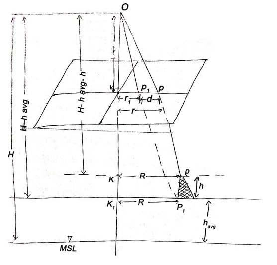
Relief and Tilt Displacement
|
|
From (1) and (2)
If the point is taken to datum, (havg – 0)
|
Shift of Image of a point on photograph, if the point is taken to detum is called relief displacement.
Tilted aerial photograph
f -focal length
n -nadir point
s –swing
p -principal point
t -angle of tilt
i –isocenter
tan (t/2) = (pi)/f ; (pi) = f tan (t/2)
tan (t) = (pn)/f ; (pn) = f tan (t)
Flight Planning
- Confirm project outline conforms to customer’s project requirements.
- Confirm project specifications or requirements for the flight plan. (scale, GSD, camera or sensor type) based on customer dialog or scope of work)
- Make the flight plan in accordance with client provided specifications.
- QC flight plan to confirms the plan adheres to project specifications/requirements.
- Export flight plan in the required format, and send to the customer for review and approval (kml, shapefile)
- After final customer approval, forward the flight plan to Flight Operations for project setup.
- Flight Ops will make a sensor specific flight plan, disseminate to the crews.
Stereoscopy
- A comboination of stereoscopic photographs or images can be viewed stereoscopically by viewing at the left image with the left eye and the right image with the right eye. It is known stereoscopy.
- Stereoscopy is based on Porro-Koppe's Principle that the same light path will be generated through an optical system if a light source is gauge onto the image taken by an optical system. The principle will be realized in a stereo model if a combination of stereoscopic images is reconstructed using the relative location or tilt at the time the photography was taken. Such an adjustment is known relative orientation in photogrammetric terms.
- The eye-base and the photo-base must be running parallel in order to view at a stereoscopic model.
Usually a stereoscope is used for image interpretation. There are several types of stereoscope, for example, portable lens stereoscope, stereo zoom transfer scope and many more.
The process of stereoscopy for aerial photographs is as follows. At first the center of both aerial photographs, known the principal point, should be noted. Secondly the principal point of the right image should be plotted in its location on the left image. At the same time the principal point of the left image should be also plotted on the right image. The principal points and shifted points should be aligned along a straight line, known as the base line, with an appropriate separati5.on.
The advantage of stereoscopy is the power to extract three dimensional information, for example, classing between tall trees and low trees, terrestrial features such as height of terraces, slope gradient, detail geomorphology in flood plains, dip of geological layers and so on.
The principle of height measurement by stereoscopic vision is based by the use of parallax, which is the distance between image points, of the same object on the ground, on the left and right image. The height difference can be computed if the parallax difference is measured between two points of different height, using a parallax bar
Ground Control extension for photography mapping
Ground control can be categorized as targeted and photo-identifiable (picked) control points, and can also be known as horizontal control, vertical only control, or as 3-D control. Horizontal and vertical controls need different configurations to make them serve their intended purposes. The use of only ground control is now restricted to small projects, such as bridge sites, borrow areas and where only one or two models are needed. Photo identifiable control points are needed. The surveyor must know what type of control is known for when he or she attempts to pick or photo-identify the point. Accessibility for surveying should also be considered while selecting the position for control points
Ground Control
- Research project region for existing control. Existing control that can be choose to save time and money by avoiding unnecessary field surveys. it is more cost efficient to expand the aerial photography slightly beyond the project area to include existing control than to make a new control.
- Selecting operations is an essential part of photogrammetric mapping to be considered prior to establishing a control survey. Preflight targeting is done to make ground locations of control points to clear on the photographs. Easy identification and clear image of the control points on the photograph increases the accuracy and efficiency of the photogrammetric procedure Highway design mapping usually requires careful pre-flight planning for optimal target placement. To reduce the possibility of pre-marked points being moved or lost prior to the aerial mission, it is important to either paint them on a hard surface or schedule the field panelling operation as near as possible to the anticipated flight. Targets should be located where shadows will not affect the visibility of the panel.
- Field surveys for photogrammetric control should be seen as ordinary surveys. The procedures that are described in the manual should be applied to photogrammetric control field work. The issue here is to choose suitable survey procedures that address the project requirements.
- Photogrammetric control points are spaced widely around the project area. For large projects, distancing could be extensive enough to require a significant surveying effort. Therefore, GPS is the better suited surveying method for largest photogrammetric projects.
- Ground control that is used in successive photogrammetric projects or field surveys should be monumented.
- Compute, adjust the field data and make a coordinate values for the control points.
- Make a report on the surveys and on the results. An accuracy analysis of the results should be included in the report. The analysis must indicate the methodology used to find that the results are in agreement with the project statement.
Application of aerial photography:
Mapping: Itis a valuable tool for soil mapping. It is found to fast, precise, indispensable in inaccessible areas and it is cost effective in the long run.
Interpretation: Photointerpretation has revolutionalised the method of data collection in many disciplines. It decreases the field work and thereby the cost. The information is reliable and acceptance for most studies forvexample as in the fields of geology, water resources, geomorphology, hydrogeology, forestry and ecology, and urban and regional planning.
Aerial Triangulation
The term applied to the process of finding out x,y, and z ground coordinate of each separate points by measuring from the photograph.
The priniciple behind this application is extending ground control through strip fro use in subsequent photogrammetric operation.
Method of Aerial triangulation: -
- Analogue Aerial triangulation
- Semi Analytical Aerial triangulation
- Analytical Aerial triangulation
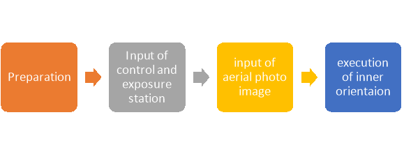
Procedure of Aerial triangulation: -
|
Benefits of aerial triangulation: -
- It minimizes delays and hardships due to worst weather condition
- Field surveying in difficult area, such as Marshes, slope, hazardous rock formation, etc; from aerial triangulation it can be minimized.
Reference
1. Principles of Surveying. Vol. I by J. G. Olliver, J. Clendinning - Van Nostrand
Reinhold.
2. Plane Surveying by A. M. Chandra, New Age International Publishers.
3. Surveying Vol. I & II by Dr. K. R. Arora, Standard Book House.
4. Elements of Photogrammetry - Paul R. Wolf, McGraw Hill Publication.
5. Remote sensing and Geographical Information System- A. M. Chandra and S. K.
Ghosh, Narosa Publishing House.
6. Advanced Surveying -Total Station, GIS and Remote Sensing – Satheesh Gopi, R.Sathikumar and N. Madhu, Pearson publication.
7.The GIS Book, 5Th Edition, George B. Korte, PE onwards press.


