Unit 2
Principles of Pipelining and Vector Processing
Have you ever visited an industrial plant works and sees the lines over there? However, a product passes through the assembly line and whereas passing it's worked on, at completely different phases at the same time. At the primary stage, the auto chassis is ready, within the next stage staff add body to the chassis, further, the engine is put in, then painting work is
The group of staff when engaged on the chassis of the primary automobile doesn’t sit idle. They begin engaged on the chassis of the following automobile. And also the next cluster takes the chassis of the automobile and adds body there to. The constant issue is continual at each stage, when finishing the work on the present automobile body they defy following automobile body that is that the output of the
Here, though' the primary automobile is completed in many hours or days, thanks to the line arrangement it becomes attainable to own a replacement automobile at the tip of an The output of the primary pipeline becomes the input for the following pipeline. It's sort of a set of knowledge process units connected asynchronous to utilize the processor up to its most.
Pipelining is a technique of rising the general process performance of a processor. This architectural approach allows the simultaneous execution of several instructions. Pipelining is clear to the programmer; it exploits parallelism at the instruction level by overlapping the execution method of directions. It is analogous to an assembly line where workers perform specific tasks and pass the partially completed product to the next worker.
The pipeline is an implementation technique that exploits parallelism among the instructions in a sequential instruction stream. The pipeline allows us to overlap the execution of multiple instructions. A Pipeline is like an assembly line each step or pipeline stage completes a part of instructions. Each stage of the pipeline will be operating a separate instruction. Instructions enter at one end progress through the stage and exit at the other end. If the stages are perfectly balanced.(Assuming ideal conditions), then the time per instruction on the pipeline processor isgiven by the ratio:
Time per instruction on un-pipelined machine/ Number of Pipeline stages
Under these conditions, the speedup from pipelining is equal to the number of stage pipeline. In practice, the pipeline stages are not perfectly balanced and the pipeline does involve some overhead. Therefore, the speedup will be always then practically less than the number of stages of the pipeline. Pipeline yields a reduction in the average execution time per instruction. If the processor is assumed to take one (long) clock cycle per instruction, then pipelining decreases the clock cycle time. If the processor is assumed to take multiple CPI, then pipelining will aid to reduce the CPI.
An instruction in a process is divided into 5 subtasks likely,

Now, understanding the division of the instruction into subtasks. Let us understand, how the n number of instructions in a process, are pipelined.
Look at the figure below the 5 instructions are pipelined. The first instruction gets completed in 5 clock cycle. After the completion of first instruction, in every new clock cycle, a new instruction completes its execution.
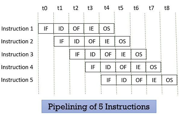
Observe that when the Instruction fetch operation of the first instruction is completed in the next clock cycle the instruction fetch of second instruction gets started. This way the hardware never sits idle it is always busy in performing some or other operation. But, no two instructions can execute their same stage at the same clock cycle.
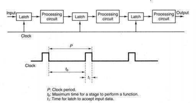
The pipeline design technique decomposes a successive method into many sub-processes, referred to as stages or segments. A stage that performs a selected perform associated produces an intermediate result. It consists of an associate input latch, additionally referred to as a register or buffer, followed by a processing circuit. (A processing circuit is a combinable or successive circuit.) The processing circuit of a given stage is connected to the input latch of the future stage .A clock signal is connected to every input latch. At every clock pulse, each stage transfers its intermediate result to the input latch of the future stage. During this manner, the ultimate result's made once the computer file has capable the whole pipeline, finishing one stage per clock pulse. The amount of the clock pulse ought to be massive enough to supply adequate time for a sign to traverse through the slowest stage, which is termed the bottleneck (i.e., the stage needing the longest quantity of your time to complete).additionally, there ought to be enough time for a latch to store its input signals. If the clock's amount, P, is expressed as P = tb tl, then tb ought to be larger than the utmost delay of the bottleneck stage, and tl oughtto be adequate for storing data into a latch.
The pipeline processors were classified supported the degree of the process by Handler in 1977.
Given below is the classification of pipeline processor by given by Handler :
An arithmetic pipeline usually breaks a mathematical process into multiple arithmetic steps. So within the arithmetic pipeline, the mathematical process like multiplication, addition, etc. is divided into a series of steps that may be dead one by one piecemeal within the Arithmetic Logic Unit (ALU).
Example of Arithmetic pipeline
Listed below are samples of arithmetic pipeline processor:
8 stage pipeline utilized in TI-ASC
4 stage pipeline utilized in Star-100
2. Processor pipeline
In a processor pipeline process of equivalent information, the stream is finished by a cascade of processors. In this, every cascade of a method or is allotted and process a particular task.
There is no sensible example found for the processor pipeline.
3. Instruction pipeline
In the instruction pipeline processor, the execution of a stream of directions is pipelined by overlapping the execution of the present instruction with the fetch, decode, and quantity fetch of future directions.
Example of the Instruction pipeline
All superior computers these days area unit equipped with an instruction pipeline processor.
1.31 Performance and Issues in Pipelining
First, we take the ideal case for measuring the speedup.
Let n be the total number of tasks executed through m stages of pipelines.
Then m stages can process n tasks in clock cycles = m + (n-1)
Time is taken to execute without pipelining = m.n
Speedup due to pipelining = m.n/[m +(n-1)]
As n>=∞, there's a speed of n times over the non-pipelined execution.
the total time span together with the idle time.
Let c be the clock period of the pipeline, the
Efficiency E can be denoted as:
E = (n. m. c) / m. [m*c + (n-1).c] = n / (m + (n-1)
As n-> ∞, E becomes 1.
T = n / [m + (n-1)]. c = E / c
Throughput denotes the computing power of the pipeline.
Maximum speed up, efficiency and throughput are the ideal cases but these are notachieved in the practical cases, as the speedup is limited due to the following factors:
the instructions of 2 tasks utilized in the pipeline. As an example, one instruction cannot
be started till the previous instruction returns the results, as each are interdependent.
Another instance of data dependency are once that each instruction try and modify
the same data object. These are known as data hazards.
Pipeline Conflicts
There are some factors that cause the pipeline to deviate from its normal performance. Some of these factors are given below:
5. Data Dependency: It arises once an instruction depends upon the results of a previous instruction however this result's not nevertheless on the market.
Advantages of Pipelining
Disadvantages of Pipelining
It is a way for compensating for the comparatively slow speed of DRAM (Dynamic RAM). During this technique, the most memory is split into memory banks which might be accessed severally with none dependency on the opposite.
For example: If we've got four memory banks(4-way Interleaved memory), with every containing 256 bytes, then, the Block destined scheme(no interleaving), can assign virtual address zero to 255 to the primary bank, 256 to 511 to the second bank. however in Interleaved memory, virtual address zero are going to be with the primary bank, one with the second memory bank, a pair of with the third bank and three with the fourth, and so four with the primary memory bank once more.
Hence, the C.P.U. will access alternate sections forthwith while not looking ahead to memory to be cached. There are multiple memory banks that move for the availability of information.
Memory interleaving could be a technique for increasing memory speed. It’s a method that creates the system a lot of economical, fast, and reliable.
For example: within the higher than example of four memory banks, information with virtual addresses zero, 1, 2, and three will be accessed at the same time as they reside in separate memory banks, thence we tend to don't have to be compelled to look ahead to the completion of information fetch, to start with, the next.
An interleaved memory with n banks is alleged to be n-way interleaved. In associate degree interleaved memory system, there are still 2 banks of DRAM however logically the system appears one bank of memory that's double as massive.
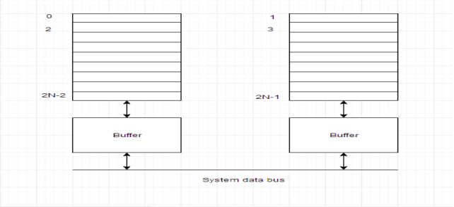
In the interleaved bank illustration below with a pair of memory banks, the primary long word of bank zero is followed by that of bank one, that is followed by the second long word of bank zero, that is followed by the second long word of bank one, and so on.
The following figure shows the organization of 2 physical banks of n long words. All even long words of the logical bank are settled in physical bank zero and every one odd long words are settled in physical bank one.
Classification of Memory Interleaving:
Memory interleaving is classified into two types:
1. High Order Interleaving –
In high-order interleaving, the foremost vital bits of the address choose the microchip. The smallest amount vital bits are sent as addresses to every chip. One downside is that consecutive addresses tend to be within the same chip. The utmost rate of data transfer is restricted by the memory cycle time.
It is conjointly referred to as Memory Banking.
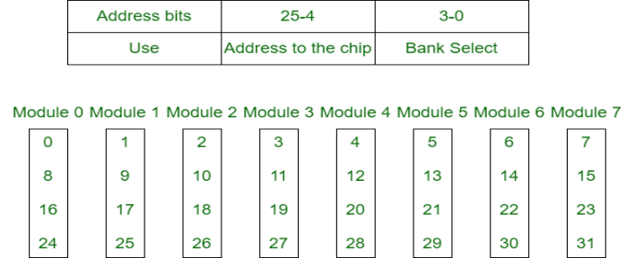
2. Low Order Interleaving–
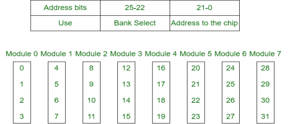
In low-order interleaving, the smallest amount vital bits choose the memory bank (module). In this, consecutive memory addresses are in numerous memory modules. This enables access at a lot of quicker rates than allowed by the cycle time.
Performance of a system depends on
• hardware technology
• architectural features
• efficient resource management
• algorithm design
• data structures
• language efficiency
• programmer skill
• compiler technology
When we talk about performance of computer system we would describe how quickly a given system can execute a program or programs. Thus we are interested in knowing the turnaround time. Turnaround time depends on:
• disk and memory accesses
• input and output
• compilation time
• operating system overhead
• CPU time
An ideal performance of a system suggests that an ideal match between the machine capability and program behaviour. Machine capability is improved by victimization better hardware technology and economical resource management. However as so much as program behaviour cares it depends on code used, the compiler used, and another run-time conditions. Also, a machine performance might vary from program to program. Because there area unit too several programs and it's impractical to check a CPU's speed on all of them, benchmarks were developed. Computer architects have return up with a spread of metrics to describe laptop performance.
Clock rate and CPI / IPC: Since I/O and system overhead oft over lap processing by different programs, it's truthful to contemplate solely the C.P.U. time utilized by a program, and the user C.P.U. time is that the most significant issue. C.P.U. is driven by a clock with a constant cycle time (usually measured in nanoseconds that control the speed of internal operations within the C.P.U. The clock largely contains a constant cycle time (t in nanoseconds).
The inverse of the cycle time is that the clock rate (f = 1/τ, measured in megahertz). A shorter
clock cycle time, or equivalently a bigger variety of cycles per second, implies additional
operations is performed per unit time. The dimensions of the program is set by the
instruction count (Ic). The dimensions of a program are set by its instruction count, Ic, the
number of machine directions to be dead by the program. Completely different machine
instructions need completely different numbers of clock cycles to execute. CPI (cycles per
instruction) is therefore a vital parameter.
Average CPI: It is straightforward to see the common variety of cycles per instruction for a selected processor if we all know the frequency of incidence of every instruction kind.
Of course, any estimate is valid just for a particular set of programs (which defines the
instruction mix), and so as long as there are a sufficiently massive numbers of directions.
In general, the term CPI is employed with relevance a selected instruction set and a given
program combine. The time needed to execute a program containing IC directions is simply T
= Ic * CPI * τ.
Each instruction should be fetched from memory, decoded, then operands fetched from
memory, the instruction dead, and also the results hold on. The time needed to access memory is named the memory cycle time, that is typically k times the processor cycle time τ. the worth of k depends on the memory technology and the processor-memory interconnection theme. The processor cycles needed for every instruction (CPI) is attributed to cycles required for instruction rewrite and execution (p), and cycles required for memory references (m* k). The total time required to execute a program will then be rewritten as
T = Ic* (p + m*k)*τ.
MIPS: The countless directions per second, this can be calculated by dividing the quantity
of directions dead in an exceedingly running program by the time needed to run the program. The MIPS rate is directly proportional to the clock rate and reciprocally proportional to the CPI. All four systems attributes (instruction set, compiler, processor, and memory
technologies) have an effect on the unit rate that varies additionally from program to program. MIPS does not encourage be effective because it doesn't account for the very fact that completely different systems often need a distinct variety of directions to implement the program. It doesn't inform regarding what number directions area unit needed to perform a given task. With the variation in instruction designs, internal organization, and variety of processors per system it is nearly unimportant for scrutiny 2 systems.
MFLOPS: (pronounced megaflops'') stands for millions of floating-point operations per second.'' this is {often this can be} often used as a bottom-line'' figure. If one is aware of sooner than time howevermany operations a program has to perform, one will divide the quantity of operations by the execution time to come back up with associate MFLOPS rating. As an example, the quality algorithm for multiplying n*n matrices needs 2n^3 –n operations (n2 inner merchandise, with n multiplications and n-1additions in every product). Suppose you cipher the product of 2 a hundred *100 matrices in zero.35 seconds. Then the pc achieves
(2(100) ^3 – 100)/0.35 = 5,714,000 ops/sec = five.714 MFLOPS
The term theoretical peak MFLOPS'' refers to what number operations per second would
be potential if the machine did nothing however numerical operations. it's obtained by
calculating the time it takes to perform one operation and so computing what number of
them may well be worn out one second. as an example, if it takes eight cycles to try to to one floating-point multiplication, the cycle time on the machine is twenty nanoseconds, and arithmetic operations aren't overlapped with each other, it takes 160ns for one multiplication, and (1,000,000,000 nanosecond/1sec)*(1 multiplication / a hundred and sixty nanosecond) = half dozen.25*106 multiplication /sec therefore the theoretical peak performance is half dozen.25 MFLOPS. Of course, programs aren't simply long sequences of multiply and add directions, therefore a machine rarely comes getting ready to this level of performance on any real program. Most machines can achieve but 100% of their peak rating, however vector processors or different machines with internal pipelines that have a good CPI close to one.0 will typically win seventieth or additional of their theoretical peak on tiny programs.
Throughput rate: Another necessary issue on that a system’s performance is measured
is the throughput of the system that is essentially what percentage programs a system will execute per unit time Ws. In execution, the system throughput is commonly under the CPU throughput Wp that is outlined as
Wp = f/(Ic * CPI)
The unit of Wp is programming/second.
Ws execution surroundings there's invariably extra overheads like timesharing OS etc. Ideal behaviour isn't achieved in parallel computers because whereas death penalty a parallel rule, the process parts cannot devote 100% of their time to the computations of the rule. Potency may be a live of the fraction of your time that an alphabetic character is usefully used. In a perfect parallel system, efficiency is capable one. In follow, potency is between zero and ones of overhead related to parallel execution.
Speed or Throughput (W/Tn) - the execution rate on AN n processor system, measured in FLOPs/unit-time or instructions/unit-time.
Speedup (Sn = T1/Tn) - what quantity quicker in AN actual machine, n processors compared to 1 can perform the work. The quantitative relation T1/T∞is referred to as the straight line quickening.
Efficiency (En = Sn/n) - a fraction of the theoretical most quickening achieved by n processors.
Degree of correspondence (DOP) - for a given piece of the work, the quantity of processors which will be unbroken busy sharing that piece of computation equally. Neglecting overhead, we tend to assume that if k processors work along on any work, the workgets done k times as quick as consecutive execution.
Scalability - The attributes of a computing system which permit it to be graciously and
linearly scaled up or down in size, to handle smaller or larger workloads, or to get
proportional decreases or will increase in speed on a given application. The applications run
on a scalable machine might not scale well. Smart scalability needs the algorithm and therefore themachine to own the correct properties
Thus generally there are 5 performance factors (Ic, p, m, k, t) that are influenced by
four system attributes:
• Instruction-set architecture (affects Ic and p)
• Compiler technology (affects Ic and p and m)
• CPU implementation and control (affects p*t) cache and memory hierarchy
(affects operation latency,kt)
• Total C.P.U. time is used as a basis in estimating the execution rate of a
processor.
There is a category of machine issues that are beyond the capabilities of a conventional computer. These issues need large range of computations on multiple data things, which will take a traditional computer (with scalar processor) days or maybe weeks to finish.
Such complicated instructions that operates on multiple data at constant time needs a much better approach of instruction execution that was achieved by Vector processors.
Scalar CPUs will manipulate one or 2 data things at a time, that isn't terribly economical. Also, straightforward instructions like ADD A to B, and store into C don't seem to be much economical.
Addresses are used to point to the memory location wherever the information to be operated are going to be found, that ends up in value-added overhead of data search. Therefore till the information is found, the mainframe would be sitting ideal, that may be a huge performance issue.
Hence, the conception of Instruction Pipeline comes into image, during which the instruction passes through many sub-units successively. These sub-units perform varied freelance functions, for example: the primary one decodes the instruction, the second sub-unit fetches the information and also the third sub-unit performs the mathematics itself. Therefore, whereas the information is fetched for one instruction, mainframe doesn't sit idle, it rather works on decryption future instruction set, ending up operating like a mechanical system.
Vector processor, not solely use Instruction pipeline, however it additionally pipelines the information, functioning on multiple data at constant time.
A normal scalar processor instruction would be ADD A, B, that ends up in addition of 2 operands, however what if we will instruct the processor to add a {group a gaggle a bunch} of numbers(from zero to n memory location) to another group of numbers(let’s say, n to k memory location). This can be achieved by vector processors.
In vector processor one instruction, will provoke multiple data operations that saves time, as instruction is decoded once, and so it keeps on operational on completely different data things.
Vector instructions can be classified as below:
• Vector-Vector Instructions: In this type, vector operands are fetched from the vector register and stored in another vector register. These instructions are denoted with the following function mappings:
F1: V -> V
F2: V × V -> V
For example, vector square root is of F1 type and addition of two vectors is of F2.
• Vector-Scalar Instructions: In this type, when the combination of scalar and vector are fetched and stored in vector register. These instructions are denoted with the following function mappings:
F3: S × V -> V where S is the scalar item
For example, vector-scalar addition or divisions are of F3 type.
• Vector reduction Instructions: When operations on vector are being reduced to scalar items as the result, then these are vector reduction instructions. These instructions are denoted with the following function mappings:
F4: V -> S
F5: V × V -> S
For example, finding the maximum, minimum and summation of all the elements of
Vector are of the type F4. The dot product of two vectors is generated by F5.
• Vector-Memory Instructions: When vector operations with memory M are performed then these are vector-memory instructions. These instructions are denoted with the following function mappings:
F6: M-> V
F7: V -> V
For example, vector load is of type F6 and vector store operation is of F7.
Vector Processing with Pipelining: Since in vector processing, vector instructions perform the same computation on different data operands repeatedly, vector processing is most suitable for pipelining. Vector processors with pipelines are designed to handle vectors of varying length n where n is the length of vector. A vector processor performs better if length of vector is larger. But large values of n causes the problem in storage of vectors and there is difficulty in moving the vectors to and from the pipelines.
Pipeline Vector processors adopt the subsequent 2 study configurations for this design problem as mentioned below:
We have seen that for acting vector operations, the pipelining idea has been used. There is another methodology for vector operations. If we've got array of n process elements (PEs) i.e., multiple ALUs for storing multiple operands of the vector, then an instruction, for instance, vector addition, is broadcast to any or all PEs such they add all operands of the vector at identical time. Which means all PEs can perform computation in parallel. All PEs square measure synchronised beneath one management unit. This organization of synchronous array of PEs for vector operations is named associate degree Array Processor. The organization is that the same as in SIMD that we tend to studied in unit two. An array processor will handle one instruction and multiple information streams as we've got seen within the case of the SIMD organization. Therefore, array processors are referred to as SIMD array computers.
The organization of associate degree array processor is shown in Figure. The subsequent parts are organized in array processor.

Control Unit (CU): All PEs area unit below the control of 1 control unit. Cu controls the inter communication between the PEs. There’s a local memory of cu also known as CY memory. The user programs area unit loaded into the cu memory. The vector instructions in the program are decoded by cu and broadcast to the array of PEs. Instruction fetch and decoding is completed by the cu solely.
Processing parts (PEs): every process part consists of ALU, its registers and
a local memory for storage of distributed information. These PEs are interconnected via AN inter connection network. All PEs receive the instructions from the control unit and also the different element operands area unit fetched from their native memory. Thus, all PEs perform the same perform synchronously during a lock-step fashion below the control of the cu. It may be attainable that each one PEs needn't participate within the execution of a vector instruction.
Therefore, it's needed to adopt a masking scheme to control the standing of every pe. A masking vector is used to control the standing of all PEs such solely enabled PEs area unit design allowed to participate within the execution and others are disabled.
Interconnection Network (IN): IN performs information exchange among the PEs, information routing and manipulation functions. This IN is below the control of cu.
Host Computer: AN array processor is also connected to a number pc through the control unit. The aim of the host pc is to broadcast a sequence of vector instructions through cu to the PEs. Thus, the host pc could be a general-purpose machine that acts as a manager of the whole system.
1.71 Systolic Arrays:
Parallel processing approach diverges from ancient von Neumann design. One such approach is that the concept of systolic process using systolic array.
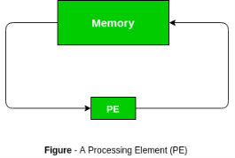
A systolic array may be a network of processors that rhythmically compute and pass data through the system. They derived their name from drawing an analogy to however blood rhythmically flows through a biological heart because the data flows from memory during a rhythmic fashion passing through several elements before it returns to memory. It is also an example of pipelining alongside parallel computing. It was introduced in Seventies and was employed by Intel to create CMU’s iWarp processor in 1990.
In a systolic array there are an outsized range of identical straightforward processors or process elements (PEs) that are organized during a well union structure like linear or 2 dimensional array. Every process component is connected with the opposite PEs and has a restricted personal storage.
Characteristics:
Advantages of systolic array –
Disadvantages of systolic array –
Reference Books: