An associative memory can be considered as a memory unit whose stored data can be identified for access by the content of the data itself rather than by an address or memory location.
Associative memory is often referred to as Content Addressable Memory (CAM).
When a write operation is performed on associative memory, no address or memory location is given to the word. The memory itself is capable of finding an empty unused location to store the word.
On the other hand, when the word is to be read from an associative memory, the content of the word, or part of the word, is specified. The words which match the specified content are located by the memory and are marked for reading.
The following diagram shows the block representation of an Associative memory.
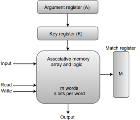
Fig 1 - block representation of an Associative memory
From the block diagram, we can say that an associative memory consists of a memory array and logic for 'm' words with 'n' bits per word.
The functional registers like the argument register A and key register K each have n bits, one for each bit of a word. The match register M consists of m bits, one for each memory word.
The words which are kept in the memory are compared in parallel with the content of the argument register.
The key register (K) provides a mask for choosing a particular field or key in the argument word. If the key register contains a binary value of all 1's, then the entire argument is compared with each memory word. Otherwise, only those bits in the argument that have 1's in their corresponding position of the key register are compared. Thus, the key provides a mask for identifying a piece of information which specifies how the reference to memory is made.
The following diagram can represent the relation between the memory array and the external registers in an associative memory.
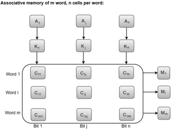
Fig 2 - the relation between the memory array and the external registers in an associative memory
The cells present inside the memory array are marked by the letter C with two subscripts. The first subscript gives the word number and the second specifies the bit position in the word. For instance, the cell Cij is the cell for bit j in word i.
A bit Aj in the argument register is compared with all the bits in column j of the array provided that Kj = 1. This process is done for all columns j = 1, 2, 3......, n.
If a match occurs between all the unmasked bits of the argument and the bits in word i, the corresponding bit Mi in the match register is set to 1. If one or more unmasked bits of the argument and the word do not match, Mi is cleared to 0.
Key takeaway
An associative memory can be considered as a memory unit whose stored data can be identified for access by the content of the data itself rather than by an address or memory location.
Associative memory is often referred to as Content Addressable Memory (CAM).
▪Memory latencies and even latencies to lower level caches are becoming longer w.r.t. processor cycle times
▪There are basically 3 ways to hide/tolerate such latencies by overlapping computation with the memory access
–Dynamic out-of-order scheduling
–Prefetching
–Multithreading
▪OOO execution and prefetching allow overlap of computation and memory access within the same thread (these were covered in CS3 Computer Architecture)
▪Multithreading allows overlap of memory access of one thread/process with computation by another thread/process
Blocked Multithreading
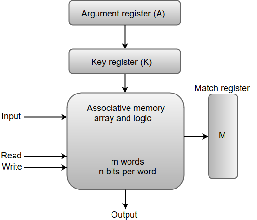
▪Basic idea:
–Unlike in multi-tasking, context is still kept in the processor and OS is not aware of any changes
–Context switch overhead is minimal (usually only a few cycles)
–Unlike in multi-tasking, the completion of the long-latency operation does not trigger a context switch (the blocked thread is simply marked as ready)
–Usually the long-latency operation is a L1 cache miss, but it can also be others, such as a fp or integer division (which takes 20 to 30 cycles and is unpipelined)
▪Context of a thread in the processor:
–Registers
–Program counter
–Stack pointer
–Other processor status words
▪Note: the term “multithreading” is commonly used to mean simply the fact that the system supports multiple threads

▪Hardware mechanisms:
–Keeping multiple contexts and supporting fast switch
▪One register file per context
▪One set of special registers (including PC) per context
–Flushing instructions from the previous context from the pipeline after a context switch
▪Note that such squashed instructions add to the context switch overhead
▪Note that keeping instructions from two different threads in the pipeline increases the complexity of the interlocking mechanism and requires that instructions be tagged with context ID throughout the pipeline
–Possibly replicating other microarchitectural structures (e.g., branch prediction tables)
▪Employed in the Sun T1 and T2 systems (a.k.a. Niagara)
▪Simple analytical performance model:
–Parameters:
▪Number of threads (N): the number of threads supported in the hardware
▪Busy time (R): time processor spends computing between context switch points
▪Switching time (C): time processor spends with each context switch
▪Latency (L): time required by the operation that triggers the switch
–To completely hide all L we need enough N such that (N-1)*R + N*C = L
▪Fewer threads mean we can’t hide all L
▪More threads are unnecessary
Note: these are only average numbers and ideally N should be bigger to accommodate variation

Fine-grain or Interleaved Multithreading
▪Basic idea:
–Instead of waiting for long-latency operation, context switch on every cycle
–Threads waiting for a long latency operation are marked not ready and are not considered for execution
–With enough threads no two instructions from the same thread are in the pipeline at the same time → no need for pipeline interlock at all
▪Advantages and disadvantages over blocked multithreading:
+ No context switch overhead (no pipeline flush)
+ Better at handling short pipeline latencies/bubbles
–Possibly poor single thread performance (each thread only gets the processor once every N cycles)
–Requires more threads to completely hide long latencies
–Slightly more complex hardware than blocked multithreading (if we want to permit multiple instructions from the same thread in the pipeline)
▪Some machines have taken this idea to the extreme and eliminated caches altogether (e.g., Cray MTA-2, with 128 threads per processor)
▪Simple analytical performance model
▪Assumption: no caches, 1 in 2 instruction is a memory access
–Parameters:
▪Number of threads (N) and Latency (L)
▪Busy time (R) is now 1 and switching time (C) is now 0

–The minimum value of N (i.e., N=L+1) is the saturation point (Nsat)
–Again, there are two regions of operation:
▪Before saturation, adding more threads increase processor utilization linearly
▪After saturation, processor utilization does not improve with more threads, but is 100% (i.e., Usat = 1)

Simultaneous Multithreading (SMT)
▪Basic idea:
–Don’t actually context switch, but on a superscalar processor fetch and issue instructions from different threads/processes simultaneously
–E.g., 4-issue processor

▪Advantages:
+ Can handle not only long latencies and pipeline bubbles but also unused issue slots
+ Full performance in single-thread mode
–Most complex hardware of all multithreading schemes
▪Fetch policies:
–Non-multithreaded fetch: only fetch instructions from one thread in each cycle, in a round-robin alternation
–Partitioned fetch: divide the total fetch bandwidth equally between some of the available threads (requires more complex fetch unit to fetch from multiple I-cache lines)
–Priority fetch: fetch more instructions for specific threads (e.g., those not in control speculation, those with the least number of instructions in the issue queue)
▪Issue policies:
–Round-robin: select one ready instruction from each ready thread in turn until all issue slots are full or there or no more ready instructions (note: should remember which thread was the last to have an instruction selected and start from there in the next cycle)
–Priority issue:
▪E.g., threads with older instructions in the issue queue are tried first
▪E.g., threads in control speculative mode are tried last
▪E.g., issue all pending branches first
Key takeaway
▪Memory latencies and even latencies to lower level caches are becoming longer w.r.t. processor cycle times
▪There are basically 3 ways to hide/tolerate such latencies by overlapping computation with the memory access
–Dynamic out-of-order scheduling
–Prefetching
–Multithreading
The speed of microprocessors has increased by more than a factor of ten per decade, but the speed of commodity memories (DRAMs) has only doubled, i.e., access time is halved. Therefore, the latency of memory access in terms of processor clock cycles grow by a factor of six in 10 years. Multiprocessors intensified the problem.
In bus-based systems, the establishment of a high-bandwidth bus between the processor and the memory tends to increase the latency of obtaining the data from the memory. When the memory is physically distributed, the latency of the network and the network interface is added to that of the accessing the local memory on the node.
Latency usually grows with the size of the machine, as more nodes imply more communication relative to computation, more jump in the network for general communication, and likely more contention. The main goal of hardware design is to reduce the latency of the data access while maintaining high, scalable bandwidth.
Overview of Latency Tolerance
How latency tolerance is handled is best understood by looking at the resources in the machine and how they are utilized. From the processor point of view, the communication architecture from one node to another can be viewed as a pipeline. The stages of the pipeline include network interfaces at the source and destination, as well as in the network links and switches along the way. There are also stages in the communication assist, the local memory/cache system, and the main processor, depending on how the architecture manages communication.
The utilization problem in the baseline communication structure is either the processor or the communication architecture is busy at a given time, and in the communication pipeline only one stage is busy at a time as the single word being transmitted makes its way from source to destination. The aim in latency tolerance is to overlap the use of these resources as much as possible.
Latency Tolerance in Explicit Message Passing
The actual transfer of data in message-passing is typically sender-initiated, using a send operation. A receive operation does not in itself motivate data to be communicated, but rather copies data from an incoming buffer into the application address space. Receiver-initiated communication is done by issuing a request message to the process that is the source of the data. The process then sends the data back via another send.
A synchronous send operation has communication latency equal to the time it takes to communicate all the data in the message to the destination, and the time for receive processing, and the time for an acknowledgment to be returned. The latency of a synchronous receive operation is its processing overhead; which includes copying the data into the application, and the additional latency if the data has not yet arrived. We would like to hide these latencies, including overheads if possible, at both ends.
Latency Tolerance in a Shared Address Space
The baseline communication is through reads and writes in a shared address space. For convenience, it is called read-write communication. Receiver-initiated communication is done with read operations that result in data from another processor’s memory or cache being accessed. If there is no caching of shared data, sender-initiated communication may be done through writes to data that are allocated in remote memories.
With cache coherence, the effect of writes is more complex: either writes leads to sender or receiver-initiated communication depends on the cache coherence protocol. Either receiver-initiated or sender-initiated, the communication in a hardware-supported read writes shared address space is naturally fine-grained, which makes tolerance latency very important.
Block Data Transfer in a Shared Address Space
In a shared address space, either by hardware or software the coalescing of data and the initiation of block transfers can be done explicitly in the user program or transparently by the system. Explicit block transfers are initiated by executing a command similar to a send in the user program. The send command is explained by the communication assist, which transfers the data in a pipelined manner from the source node to the destination. At the destination, the communication assist pulls the data words in from the network interface and stores them in the specified locations.
There are two prime differences from send-receive message passing, both of which arise from the fact that the sending process can directly specify the program data structures where the data is to be placed at the destination, since these locations are in the shared address space.
Proceeding Past Long-latency Events in a Shared Address Space
If the memory operation is made non-blocking, a processor can proceed past a memory operation to other instructions. For writes, this is usually quite simple to implement if the write is put in a write buffer, and the processor goes on while the buffer takes care of issuing the write to the memory system and tracking its completion as required. The difference is that unlike a write, a read is generally followed very soon by an instruction that needs the value returned by the read.
Pre-communication in a Shared Address Space
Pre-communication is a technique that has already been widely adopted in commercial microprocessors, and its importance is likely to increase in the future. A prefetch instruction does not replace the actual read of the data item, and the prefetch instruction itself must be non-blocking, if it is to achieve its goal of hiding latency through overlap.
In this case, as shared data is not cached, the prefetched data is brought into a special hardware structure called a prefetch buffer. When the word is actually read into a register in the next iteration, it is read from the head of the prefetch buffer rather than from memory. If the latency to hide were much bigger than the time to compute single loop iteration, we would prefetch several iterations ahead and there would potentially be several words in the prefetch buffer at a time.
Multithreading in a Shared Address Space
In terms of hiding different types of latency, hardware-supported multithreading is perhaps the versatile technique. It has the following conceptual advantages over other approaches −
This trend may change in future, as latencies are becoming increasingly longer as compared to processor speeds. Also with more sophisticated microprocessors that already provide methods that can be extended for multithreading, and with new multithreading techniques being developed to combine multithreading with instruction-level parallelism, this trend certainly seems to be undergoing some change in future.
Key takeaway
The speed of microprocessors has increased by more than a factor of ten per decade, but the speed of commodity memories (DRAMs) has only doubled, i.e., access time is halved. Therefore, the latency of memory access in terms of processor clock cycles grow by a factor of six in 10 years. Multiprocessors intensified the problem.
There are several disadvantages in Symmetric Shared Memory architectures.
Ø First, compiler mechanisms for transparent software cache coherence are very limited.
Ø Second, without cache coherence, the multiprocessor loses the advantage of being able to fetch and use multiple words in a single cache block for close to the cost of fetching one word.
Ø Third, mechanisms for tolerating latency such as prefetch are more useful when they can fetch multiple words, such as a cache block, and where the fetched data remain coherent; we will examine this advantage in more detail later.
These disadvantages are magnified by the large latency of access to remote memory versus a local cache. For these reasons, cache coherence is an accepted requirement in small-scale multiprocessors.
For larger-scale architectures, there are new challenges to extending the cache-coherent shared-memory model. Although the bus can certainly be replaced with a more scalable interconnection network and we could certainly distribute the memory so that the memory bandwidth could also be scaled, the lack of scalability of the snooping coherence scheme needs to be addressed is known as Distributed Shared Memory architecture.
The first coherence protocol is known as a directory protocol. A directory keeps the state of every block that may be cached. Information in the directory includes which caches have copies of the block, whether it is dirty, and so on.
To prevent the directory from becoming the bottleneck, directory entries can be distributed along with the memory, so that different directory accesses can go to different locations, just as different memory requests go to different memories. A distributed directory retains the characteristic that the sharing status of a block is always in a single known location. This property is what allows the coherence protocol to avoid broadcast.
Figure 3.5 shows how our distributed-memory multiprocessor looks with the directories
Added to each node.
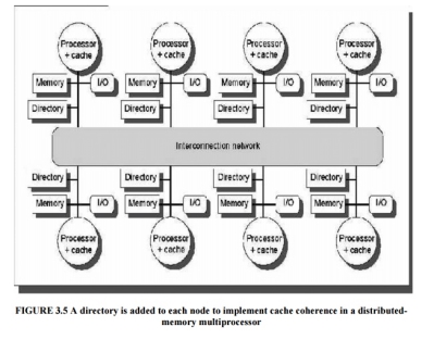
Fig 3 - Shows how our distributed-memory multiprocessor looks with the directories
Directory-Based Cache-Coherence Protocols: The Basics
There are two primary operations that a directory protocol must implement:
Ø handling a read miss and handling a write to a shared, clean cache block. (Handling a write miss to a shared block is a simple combination of these two.)
Ø To implement these operations, a directory must track the state of each cache block.
In a simple protocol, these states could be the following:
Ø Shared—One or more processors have the block cached, and the value in memory is up to date (as well as in all the caches)
Ø Uncached—No processor has a copy of the cache block
Exclusive—Exactly one processor has a copy of the cache block and it has written the block, so the memory copy is out of date. The processor is called the owner of the block.
In addition to tracking the state of each cache block, we must track the processors that have copies of the block when it is shared, since they will need to be invalidated on a write.
The simplest way to do this is to keep a bit vector for each memory block. When the block is shared, each bit of the vector indicates whether the corresponding processor has a copy of that block. We can also use the bit vector to keep track of the owner of the block when the block is in the exclusive state. For efficiency reasons, we also track the state of each cache block at the individual caches.
A catalog of the message types that may be sent between the processors and t he directories. Figure 6.28 shows the type of messages sent among nodes. The local node is the node where a request originates.
The home node is the node where the memory location and the directory entry of an address reside. The physical address space is statically distributed, so the node that contains the memory and directory for a given physical address is known.
For example, the high-order bits may provide the node number, while the low-order bits provide the offset within the memory on that node. The local node may also be the home node. The directory must be accessed when the home node is the local node, since copies may exist in yet a third node, called a remote node.
A remote node is the node that has a copy of a cache block, whether exclusive (in which case it is the only copy) or shared. A remote node may be the same as either the local node or the home node. In such cases, the basic protocol does not change, but interprocessor messages may be replaced with intraprocessor messages.
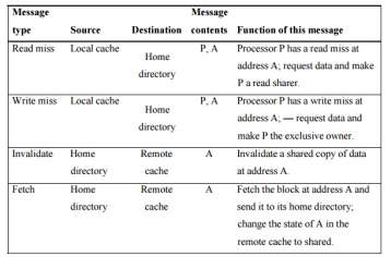
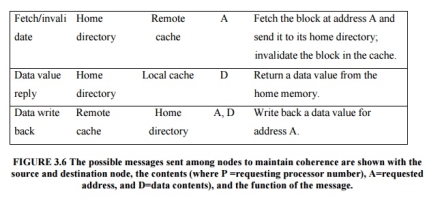
Fig 4 – The possible message sent among nodes to maintain coherence
Key takeaway
Ø First, compiler mechanisms for transparent software cache coherence are very limited.
Ø Second, without cache coherence, the multiprocessor loses the advantage of being able to fetch and use multiple words in a single cache block for close to the cost of fetching one word.
Ø Third, mechanisms for tolerating latency such as prefetch are more useful when they can fetch multiple words, such as a cache block, and where the fetched data remain coherent
Text Books:
Reference Books: