Unit -3
Advanced SQL
PL/SQL (Procedural Language/SQL) is extension to SQL. PL/SQL consist two versions first is a component of the Oracle server, and second is a separate engine embedded during a number of Oracle tools. They very almost like one another and have an equivalent programming constructs, syntax, and logic mechanisms, although PL/SQL for Oracle tools has some extensions to suit the wants of the actual tool.
PL/SQL has concepts almost like modern programming languages, like variable and constant declarations, control structures, exception handling, and modularization. PL/SQL is a block-structured language and blocks are separate or nested within each other.
The PL/SQL programming language was developed by Oracle Corporation as procedural extension language for SQL and therefore the Oracle relational database. Following are some facts about PL/SQL
• PL/SQL is a portable, high-performance transaction-processing language.
• PL/SQL provides a built-in, interpreted and OS independent programming environment.
• PL/SQL also can directly be called from the command-line SQL*Plus interface.
• Direct call is made up of external programing language calls to database.
• PL/SQL's general syntax is designed depends on ADA and Pascal programming language.
• Aside from Oracle, PL/SQL is out there in TimesTen in-memory database and IBM DB2.
Features of PL/SQL
PL/SQL has the subsequent features
Advantages of PL/SQL
PL/SQL has the following advantages
3.1.1 Basic Introduction
The basic units contains a PL/SQL program are procedures, functions, and anonymous blocks. A PL/SQL block has up to 3 parts:
• An optional declaration part, during which variables, constants, cursors, and exceptions are defined and possibly initialized;
• A compulsory executable part, during which the variables are manipulated;
• Exception part which is optional used to handle any exceptions raised during execution.
Declarations
Variables and constant variables can be declared before they are referenced inother statements, including other declarative statements. Examples of declarations are:
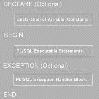
Figure 3.1.1(I)General structureof a PL/SQLblock.
vStaffNo VARCHAR2(5);
vRent NUMBER(6, 2) NOT NULL :5 600;
MAX_PROPERTIES CONSTANT NUMBER: 5 100;
It is possible to declare a variable as NOT NULL and initial value must be assigned to the variable. it's also possible to declare a variable to be of an equivalent type as a column during a specified table or another variable using the type attribute. for instance , to declare that the vStaffNo variable is that the same type because the staffNo column of the Staff table, we write as:
vStaffNoStaff.staffNo %TYPE;
vStaffNo1vStaffNo%TYPE;
Same as we will declare a variable to be of an equivalent type as a whole row of a table or view using the %ROWTYPE attribute. during this case, the fields within the record take their names and data types from the columns within the table or view. for instance , to declare a vStaffRec variable to be a row from the Staff table, we could write:
vStaffRec Staff %ROWTYPE;
%TYPE and %ROWTYPE aren't standard SQL.
Assignments
In the executable a part of a PL/SQL block, variables are often assigned in two ways: using the traditional assignment statement (:5) or because the results of an SQL SELECT or FETCH statement. For example:
vStaffNo :5 ‘SG14’;
vRent :5 500;
SELECT COUNT(*) INTO x FROM PropertyForRent WHERE staffNo 5 vStaffNo;
In the third case, the variable x is about to the results of the SELECT statement. within the SQL standard, an assignment uses the SET keyword at the beginning of the line with the “5” symbol, rather than the “:5”. For example:
SET vStaffNo 5 ‘SG14’
Control Statements
PL/SQL supports the standard conditional, iterative, and sequential flow-of-control mechanisms. Conditional IF statement The IF statement has the subsequent form:
IF (condition) THEN
[ELSIF (condition) THEN ]
[ELSE ]
END IF;
The SQL standard specifies ELSEIF rather than ELSIF. For example:
IF (position 5 ‘Manager’) THEN
salary :5 salary*1.05;
ELSE
salary :5 salary*1.03;
END IF;
Conditional CASE statement The CASE statement allows the choice of an execution path supported a group of alternatives and has the following form:
CASE (operand)
[WHEN (whenOperandList) | WHEN (searchCondition)
THEN ]
[ELSE ]
END CASE;
For example:
UPDATE Emp CASE lowercase(x) SET salary 5 CASE WHEN ‘a’ THEN x :5 1;
WHEN position 5 ‘Manager’ WHEN ‘b’ THEN x: 5 2;
THEN salary * 1.05 y :5 0;
ELSE
WHEN ‘default’ THEN x :5 3;
THEN salary * 1.03
END CASE;
END;
Iteration statement (LOOP) The LOOP statement has the subsequent form:
[labelName:]
LOOP
<SQL statement list>
EXIT [labelName] [WHEN (condition)]
END LOOP [labelName];
Consider that the SQL standard specifies LEAVE instead of EXIT WHEN (condition).
For example:
x:51;
myLoop:
LOOP
x :5 x11;
IF (x . 3) THEN
EXIT myLoop; --- exit loop immediately
END LOOP myLoop;
--- control resumes here
y :5 2;
In above example, the loop is terminated when x becomes greater than 3 and controlresumes immediately after the END LOOP keyword.
Iteration statement the WHILE and REPEAT statements have the following form
PL/SQL SQL
WHILE (condition) LOOP
<SQL statement list>
END LOOP [labelName]; WHILE (condition) DO
<SQL statement list>
END WHILE [labelName];
REPEAT
<SQL statement list>
UNTIL (condition)
END REPEAT [labelName];
Iteration statement FOR has the following form:
PL/SQL SQL
FOR indexVariable
IN lowerBound ..upperBound LOOP
<SQL statement list>
END LOOP [labelName]; FOR indexVariable
AS querySpecification DO
<SQL statement list>
END FOR [labelName];
The following is an example of a FOR loop in PL/SQL:
DECLARE
numberOfStaff NUMBER;
SELECT COUNT(*) INTO numberOfStaff FROM PropertyForRent
WHERE staffNo 5 ‘SG14’;myLoop1:
FOR iStaff IN 1 ..numberOfStaff LOOP
.....
END LOOP
myLoop1;
Subprograms are named PL/SQL blocks it take parameters and be invoked. PL/SQL has two forms of subprogram called procedures and functions. Procedures and functions can take a group of parameters given to them by the calling program and perform a group of actions. Both can modify and return data passed to them as a parameter. The difference between a procedure and a function is that a function will always return one value to the caller, whereas a procedure doesn’t. Usually, procedures are used unless just one return value is required .Procedures and functions are very similar to those found in most high-levelprogramming languages, and have an advantages like they supply modularity and extensibility, reusability, maintainability, and abstraction. A parameter features define a name and data type but also can be designated as:
• IN – parameter is used for input value only.
• OUT – parameter is used to output value only.
• IN OUT – parameter is used as both an input and an output value.
For example, we could change the anonymous PL/SQL block into a procedure by adding the subsequent lines at the start:
CREATE OR REPLACE PROCEDURE PropertiesForStaff
(IN vStaffNo VARCHAR2)
AS . . .
The procedure could then be executed in SQL*Plus as:
SQL> SET SERVEROUTPUT ON;
SQL> EXECUTE PropertiesForStaff (‘SG14’);
One easy way to determine whether a view are often used to update a base table is to look at the view’s output. If the first key columns of the base table you would like to update still have unique values within the view, the base table is updatable.
After creating the updatable view you'll use the UPDATE command to update the view. Figure shows how the UPDATE command is used and the final contents of the PRODMASTER table are after the UPDATE has been executed.
FIGURE 8.27 PRODMASTER table update, using an updatable view
Although the batch update procedure just illustrated meets the goal of updating a master table with data from a transaction table, the popular real-world solution to the update problem is to use procedural SQL.
Procedural SQL
You have learned to use SQL to read, write, and delete data within the database. For example, you learned to update values during a record, to add records, and to delete records. Unfortunately, SQL doesn't support the conditional execution of procedures that are typically supported by a programming language using the overall format:
IF
THEN
ELSE
SQL also fails to support the looping operations in programming languages that allow the execution of repetitive actions typically encountered during a programming environment. The standard format is:
DO WHILE
END DO
Traditionally, if you wanted to perform a conditional (IF-THEN-ELSE) or looping (DO-WHILE) form of operation, you'd use a programming language like Visual Basic .NET, C#, or COBOL. That’s why many older business applications are supported enormous numbers of COBOL program lines. Although that approach remains common, it always involves the duplication of application code in many programs. Therefore, when procedural changes are needed then program modifications are performed in various programs. An environment characterized by such redundancies creates data management problems.
A better approach is to isolate critical code then have all application programs call the shared code. The advantage of that modular approach is that the appliance code is isolated during a single program, thus yielding better maintenance and logic control. In any case, the increase of distributed databases and object-oriented databases required that more application code be stored and executed within the database. To fulfill that requirement, most RDBMS vendors created numerous programming language extensions. Those extensions include:
• Flow-control procedural programming structures like IF-THEN-ELSE, DO-WHILE for logic representation.
• Variable declaration and designation within the procedures.
• Error management.
A persistent stored module (PSM) is a block of code contains standard SQL statements and procedural extensions that's stored and executed at the DBMS server. The PSM describe business logic which will be encapsulated, stored, and shared among multiple database users. A PSM lets an administrator assign specific access rights to a stored module to make sure that only authorized users can use it. Support for persistent stored modules is left to every vendor to implement. In fact, for several years, some RDBMSs like Oracle, SQL Server, and DB2 supported stored procedure modules within the database before the official standard was promulgated.
MS SQL Server implements persistent stored modules through the Transact-SQL and other language extensions.
Oracle implements PSMs through its procedural SQL language. Procedural SQL that is PL/SQL is a language that creates it possible to use and store procedural code and SQL statements within the database and to merge SQL and traditional programming parts same as variables, conditional processing (IF-THEN-ELSE), basic loops (FOR and WHILE loops,) and error trapping. The procedural code is executed as a unit by the DBMS when it is executed by the end user. End users can use PL/SQL to create:
• Anonymous PL/SQL blocks.
• Triggers.
• Stored procedures.
• PL/SQL functions.
SQL built-in functions are used only within SQL statements, while PL/SQL functions are used in PL/SQL programs like triggers and stored procedures. Functions are called within SQL statements, as long as they conform to very specific rules that are dependent on your DBMS environment.
PL/SQL, triggers, and stored procedures are described within the context of an Oracle DBMS. All examples within the following sections consider the utilization of Oracle RDBMS. Using Oracle SQL*Plus, you'll write a PL/SQL code block by enclosing the commands inside BEGIN and END clauses.
BEGIN
INSERT INTO VENDOR
VALUES (25678,'Microsoft Corp. ', 'Bill Gates','765','546-8484','WA','N');
END;
/
PL/SQL block executes when you press the Enter key after typing the forward slash. Following the PL/SQL block’s execution, you'll see the message “PL/SQL procedure successfully completed.”
But suppose that you simply need a more specific message displayed on the SQL*Plus screen after a procedure is completed, like “New Vendor Added.” to supply a more specific message, you need to perform two things:
1. At the SQL > prompt, type SET SERVEROUTPUT ON. This SQL*Plus command enables the client console to receive messages from the server side.
2. To display the output on console it use the DBMS_OUTPUT.PUT_LINE function.
The following anonymous PL/SQL block inserts a row within the VENDOR table and displays the message “New Vendor Added!”
BEGIN
INSERT INTO VENDOR
VALUES (25772,'Clue Store', 'Issac Hayes', '456','323-2009', 'VA', 'N');
DBMS_OUTPUT.PUT_LINE ('New Vendor Added!');
END;
/
In Oracle, you'll use the SQL*Plus command SHOW ERRORS to diagnose errors found in PL/SQL blocks.
The SHOW ERRORS command perform additional debugging information when you generate an error after creating or executing a PL/SQL block.
The following example of an anonymous PL/SQL block shows several of the constructs supported by the procedural language.
DECLARE
W_P1 NUMBER(3) := 0;
W_P2 NUMBER(3) := 10;
W_NUM NUMBER(2) := 0;
BEGIN
WHILE W_P2 < 300 LOOP
SELECT COUNT (P_CODE) INTO W_NUM FROM PRODUCT
WHERE P_PRICE BETWEEN W_P1 AND W_P2;
DBMS_OUTPUT.PUT_LINE ('There are ' || W_NUM || ' Products with price between ' || W_P1|| ' and ' || W_P2);
W_P1:= W_P2 + 1;
W_P2:= W_P2 + 50;
END LOOP;
END;
/
The block’s code and execution are shown in Figure.
The PL/SQL block has the following characteristics:
TABLEPL/SQL Basic Data Types
DATA TYPE | DESCRIPTION |
CHAR
| Character values of a fixed length; for example: W_ZIP CHAR(5) |
VARCHAR2
| Variable length character values; for example: W_FNAME VARCHAR2(15) |
NUMBER
| Numeric values; for example: W_PRICE NUMBER(6,2) |
DATE
| Date values; for example: W_EMP_DOB DATE |
%TYPE
| Inherits the data type from a variable that you declared previously or from an attribute of a database table; for example: W_PRICE PRODUCT.P_PRICE%TYPE |
Assigns W_PRICE an equivalent data type as the P_PRICE column within the PRODUCT table
A WHILE loop is used. The syntax is:
WHILE condition LOOP
PL/SQL statements;
END LOOP
• The SELECT statement uses the INTO keyword to assign the output of the query to a PL/SQL variable. You’ll use the INTO keyword only inside a PL/SQL block of code. If the SELECT statement returns more than one value, you'll get an error.
• Note the utilization of the string concatenation symbol “||” to display the output.
• Each statement inside the PL/SQL code must end with a semicolon “;”.
PL/SQL blocks can contain only standard SQL data manipulation language (DML) commands like SELECT, INSERT, UPDATE, and DELETE. The use of data definition language (DDL) commands isn't directly supported during a PL/SQL block.
The most useful feature of PL/SQL blocks is that they allow you to create code which will be named, stored, and executed either implicitly or explicitly by the DBMS. That capability is particularly desirable once you got to use triggers and stored procedures.
Triggers
Automating business procedures and to maintaining data integrity and consistency are difficult in modern business environment. The most difficult business procedures is proper inventory management. For instance, you need to sure that current product sales are supported with sufficient product availability.
Therefore, it's necessary to make sure that a product order be written to a vendor when that product’s inventory drops below its minimum allowable quantity on hand. For automatic product ordering need to make sure that the product’s quantity which reflects an up-to-date and consistent value. After the actual product availability requirements are set, two key issues are occurred:
1. Business logic need an update of the product quantity on hand whenever there's a sale of that product.
2. If the product’s quantity falls down its minimum allowable inventory level, the product need to be reordered.
To complete these two tasks, you'll write multiple SQL statements: one to update the product quantity available and another to update the product reorder flag. There’s need to run every statement within the correct order whenever there was a new sale. Such a multistage process no sufficient because a series of SQL statements must be written and executed whenever a product is sold.
A trigger is procedural SQL code which is automatically fired by the RDBMS when event is occurred because of the Data manipulation. It’s useful to remember that:
• A trigger is executed before or after a data row is inserted, updated, or deleted.
• A trigger is related to a database tables.
• Every database table contains one or more triggers.
• A trigger is executed as a part of the transaction.
Triggers are critical to proper database operation and management. For example:
• Triggers are used to apply constraints that can't be enforced at the DBMS design and implementation levels.
• Triggers add functionality by automating critical actions and providing appropriate warnings and suggestions for remedial action. In fact, one among the most common uses for triggers is to facilitate the enforcement of referential integrity.
• Triggers are often used to update table values, insert records in tables, and call other stored procedures.
Triggers play a critical role in making the database truly useful; they also add processing power to the RDBMS and to the database system as an entire. Oracle used triggers for:
• Auditing purposes (creating audit logs).
• Automatic generation of derived column values.
• Enforcement of business or security constraints.
• Creation of replica tables for backup purposes.
To understand trigger consider the example of inventory management problem. I this if a product’s quantity on hand is updated when the product is sold, the system automatically check whether the quantity on hand falls below its minimum allowable quantity or not.
The syntax to make a trigger in Oracle is:
CREATE OR REPLACE TRIGGER trigger_name
[BEFORE / AFTER] [DELETE / INSERT / UPDATE OF column_name] ON table_name
[FOR EACH ROW]
[DECLARE]
[variable_namedata type[:=initial_value] ]
BEGIN
PL/SQL instructions;
..........
END;
A trigger definition contains the following parts:
• The triggering timing: BEFORE or AFTER. This timing shows when the trigger’s PL/SQL code executes that before or after the triggering statement is completed.
• The triggering event: With help of the statement trigger work to execute (INSERT, UPDATE, or DELETE).
• The triggering level: Two types of triggers are present likestatement-level triggers and row-level triggers.
A statement-level trigger is consider if you omit the for every ROW keywords. This type of trigger is executed once, before or after the triggering statement is completed.
A row-level trigger needs use of the for every ROW keywords. This type of trigger is executed once for every row affected by the triggering statement. The triggering action: The PL/SQL code enclosed between the BEGIN and END keywords. Every statement inside the PL/SQL code need to end with a semicolon “;”.
Stored Procedures
A stored procedure is a set of procedural and SQL statements. Same as database triggers, stored procedures are stored within the database. The main advantages is that they're used to encapsulate and represent business transactions. For example, you'll create a stored procedure to show a product sale, a credit update, or the addition of a new customer. By performing that, you'll encapsulate SQL statements within one stored procedure and execute them as a single transaction. There are two advantages of stored procedures:
• Stored procedures substantially minimize network traffic and increase performance. Because the procedure is stored at the server and there's no transmission of individual SQL statements over the network. The use of stored procedures boosts system performance because all transactions are executed locally on the RDBMS, so every SQL statement doesn't need to travel over the network.
• Stored procedures help reduce code duplication by means of code isolation and code sharing, thereby minimizing the prospect of errors and therefore the cost of application development and maintenance.
To create a stored procedure, you use the following syntax:
CREATE OR REPLACE PROCEDURE procedure_name [(argument [IN/OUT] data-type, A)]
[IS/AS]
[variable_namedata type[:=initial_value] ]
BEGIN
PL/SQL or SQL statements;
...
END;
Following are the details about stored procedures and their syntax:
• Argument specifies the parameters that are passed to the stored procedure. A stored procedure could have zero or more arguments or parameters.
• IN/OUT indicates whether the parameter is for input, output, or both.
• Data-type is one among the procedural SQL data types used in the RDBMS. The data types normally match those used in the RDBMS table-creation statement.
• Variables are often declared between the keywords IS and start. You want to specify the variable name, its data type, and an initial value.
PL/SQL Processing with Cursors
All of the SQL statements you've got used inside a PL/SQL block have returned a single value. If the SQL statement returns more than one value, you'll generate an error. If you would like to use an SQL statement that returns more than one value inside your PL/SQL code, you would like to use a cursor.
A cursor may be a special construct used in procedural SQL to carry the data rows returned by an SQL query. You’ll consider a cursor as a reserved area of memory during which the output of the query is stored, like an array containing columns and rows. Cursors are held during a reserved memory area within the DBMS server, not within the client computer.
There are two forms of cursors as implicit cursors and explicit cursors. An implicit cursor is automatically created in procedural SQL when the SQL statement returns only one value. An explicit cursor is used to hold the output of an SQL statement which will return two or more rows. To make an explicit cursor, you use the following syntax inside a PL/SQL DECLARE section:
CURSOR cursor_name IS select-query;
Once you've got declared a cursor, you'll use specific PL/SQL cursor processing commands OPEN, FETCH, and CLOSE anywhere between the BEGIN and END keywords of the PL/SQL block.
1. OPEN
Opening the cursor executes the SQL command and use the cursor with data for opening the cursor for processing. The cursor declaration command only reserves a named memory area for the cursor. Before you'll use a cursor requiredto open it. For example:
OPEN cursor_name
2. FETCH
Once the cursor is opened, you'll use the FETCH command to retrieve data from the cursor and copy it to the PL/SQL variables for processing. The syntax is:
FETCH cursor_name INTO variable1 [, variable2, ...]
The PL/SQL variables used to hold the data need to declared within the DECLARE section and must have data types compatible with the columns retrieved by the SQL command. If the cursors SQL statement returns five columns, there's five PL/SQL variables to receive the data from the cursor.
This type of processing resembles the one-record-at-a-time processing utilized in previous database models. The first time you fetch a row from the cursor, the first row of data from the cursor is copied to the PL/SQL variables; the second time you fetch a row from the cursor, the second row of data is placed within the PL/SQL variables; then on.
3. CLOSE
The CLOSE command closes the cursor for processing. Cursor-style processing take a part for retrieving data from the cursor one row at a time. Once you open a cursor, it becomes an active data set. That data set contains a “current” row pointer. Therefore, after opening a cursor, the present row is that the first row of the cursor.
When you fetch a row from the cursor, the data from the “current” row within the cursor is copied to the PL/SQL variables. After the fetch, the “current” row pointer moves to subsequent row within the set and continues until it reaches the end of the cursor.
Following are the cursor attributes.
%ROWCOUNT Returns the amount of rows fetched thus far. If the cursor isn't OPEN, it returns an error. If no FETCH has been done but the cursor is OPEN, it returns 0.
%FOUND Returns TRUE if the last FETCH returned a row and FALSE if not. If the cursor isn't OPEN, it returns an error. If no FETCH performed then it contains NULL.
%NOTFOUND this attribute returns TRUE when last FETCH didn't return any row and FALSE. If the cursor isn't OPEN, it returns an error. If no FETCH has done, it contains NULL.
%ISOPEN Returns TRUE if the cursor is open and ready for processing or FALSE if the cursor is closed.
There is need to before you'll use a cursor, you want to open it.
PL/SQL Stored Functions
Using programmable or procedural SQL, you'll create your own stored functions. Stored procedures and functions are same. A stored function may be a named group of procedural and SQL statements that returns a value. To make a function, you use the following
Syntax:
CREATE FUNCTION function_name (argument IN data-type, A) RETURN data-type [IS]
BEGIN
PL/SQL statements;
...
RETURN (value or expression);
END;
Stored functions are often executed only from within stored procedures or triggers and can't be invoked from SQL statements.
A package may be a collection of procedures, functions, variables, and SQL statements that are grouped together and stored as one program unit. A package has two parts: a specification and a body. A package specification defines all public constructs of the package, and then the body defines all constructs that is public and private of the package, and implements the specification. In this packages provide a type of encapsulation. Oracle performs the following steps when a procedure or package is created:
• It compiles the procedure or package.
• It stores the compiled code in memory.
• It stores the procedure or package within the database.
We can create a package as:
CREATE OR REPLACE PACKAGE Staff_PropertiesPackage ASprocedure Properties_ForStaff (vStaffNo VARCHAR2);
END Staff_PropertiesPackage ;
and we create the package body as:
CREATE OR REPLACE PACKAGE BODY Staff_PropertiesPackage
AS
. . .
END Staff_PropertiesPackage ;
To reference the items declared within a package specification, we use the dotnotation. For example, we call the Properties_ForStaff procedure as follows:
Staff_PropertiesPackage .Properties_ForStaff (‘SG14’);
A synonym is an alternate name for objects like tables, views, sequences, stored procedures, and other database objects. Youuse synonyms once you are granting access to an object from another schema and you do not want the users to have to worry about undestanding which schema owns the object.
Create Synonym (or Replace)
To create a synonym users do not have to prefix the table name with the schema name when using the table in a query.
Syntax
The syntax to create a synonym in Oracle is:
CREATE [OR REPLACE] [PUBLIC] SYNONYM [schema .] synonym_name
FOR [schema .] object_name [@ dblink];
OR REPLACE
Allows you to recreate the synonym without having to issue a DROP synonym command.
PUBLIC
It means the synonym can be a public synonym and is accessible to all or any users. The user must first have the appropriate privileges to the object to use the synonym.
Schema
The appropriate schema. If this phrase is omitted, Oracle consider that you are referring to your own schema.
object_name
Following are the name of the object for which you are creating the synonym.
Example
Let's consider example of how to create a synonym in Oracle.
For example:
CREATE PUBLIC SYNONYM suppliersFOR app.suppliers;
This first example shows how to create a synonym called suppliers. Now, users of other schemas can reference the table called suppliers without prefix the table name with the schema named app. For example:
SELECT *FROM suppliers;
If this synonym already existed and you need to redefine it, you can use the OR REPLACE phrase as follows:
CREATE OR REPLACE PUBLIC SYNONYM suppliersFOR app.suppliers;
Drop synonym
When synonym is created in Oracle some time there is need to drop the synonym.
Syntax
The syntax to drop a synonym is:
DROP [PUBLIC] SYNONYM [schema] synonym_name [force];
PUBLIC
Allows you to drop a public synonym. If you have specified PUBLIC, then you need not to specify a schema.
force
It will force to drop the synonym even if it has dependencies. It is bad idea to use force as it can cause invalidation of Oracle objects.
Example
Consider an example of how to drop a synonym in Oracle.
For example:
DROP PUBLIC SYNONYM suppliers;
This DROP statement drop the synonym called suppliers.
The central concept in distributed database systems can be a database link. A database link is a connection between two physical database servers that allow a client to access them together logical database.
A database link may be a pointer that defines a one-way communication path from an Oracle Database server to a different database server. The link pointer is really defined as an entry during a data dictionary table. To access the link, you need to be connected to the local database that contains the data dictionary entry.
A database link connection is one-way that a client connected to local database A can use a link stored in database A to access information in remote database B, but users connected to database B cannot use an equivalent link to access data in database A. If local users on database B want to access data on database A, then they need to define a link that's stored within the data dictionary of database B.
A database link connection allows local users to access data on a foreign database. For this connection to occur for every database within the distributed system must need a unique global database name within the network domain. The worldwide database name uniquely identifies a database server during a distributed system.
Following figure shows example of user scott accessing the emp table on the remote database with the help of worldwide name hq.acme.com:
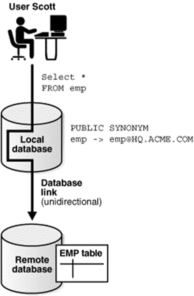
Figure 3.5(I) DatabaseLink
Database links are either private or public. If they're private, then only the user who created the link has access; if they're public, then all database users have access.
The difference between database links is that the way that connections to a foreign database occur. Users access a remote database through the following kinds of links:
Type of Link | Description |
Connected user link | Users connect as themselves, which suggests that they need to have an account on the remote database with an equivalent username and password as their account on the local database. |
Fixed user link | Users connect using the username and password referenced in the link. For example, if Jane uses a fixed user link that connects to the hq database with the username and password scott/tiger, then she connects as scott, Jane has all the privileges in hq granted to scott directly, and all the default roles that scott has been granted in the hq database. |
Current user link | A user connects as a worldwide user. A local user connect as a worldwide user within the context of a stored procedure, without storing the worldwide user's password during a link definition. For instance, Jane access a procedure that Scott wrote, accessing Scott's account and Scott's schema on the hq database. Current user links are part of Oracle Advanced Security. |
Create database links using the CREATE DATABASE LINK statement. After creation of link use it to display schema objects in SQL statements.
Need of Database Links
The great advantage of database links is that they permit users to access another user's objects during a remote database in order that they're bounded by the privilege set of the object owner. A local user can access a link to a remote database without having a user on the remote database.
For example consider that employees submit expense reports to Accounts Payable (A/P), and suppose that a user using an A/P application need to retrieve information of employees from the hq database. The A/P users ready to hook up with the hq database and execute a stored procedure within the remote hq database that retrieves the specified information. The A/P users shouldn't got hq database users to try to do their jobs; they only ready to access hq information during a controlled way as limited by the procedure.
Names for Database Links
A database link has an equivalent name because the global database name of the remote database that it references. For example, if the worldwide database name of a database is sales.us.oracle.com, then the database link is additionally called sales.us.oracle.com.
When you set the initialization parameter GLOBAL_NAMES to TRUE, the database make sure that the name of the database link is same because the global database name of the remote database. For example, if the worldwide database name for hq is hq.acme.com, and GLOBAL_NAMES is TRUE, then the link name need to called hq.acme.com. The database checks the domain a part of the worldwide database name as stored within the data dictionary, not the DB_DOMAIN setting within the initialization parameter file.
If you set the initialization parameter GLOBAL_NAMES to FALSE, then you're not need to use global naming. For instance, you'll name a database link to hq.acme.com as foo.
Types of Database Links
Oracle Database support you to create private, public, and global database links.
Type | Owner | Description |
Private | User who created the link. View ownership data with the help of: DBA_DB_LINKS ALL_DB_LINKS USER_DB_LINKS | Creates link during a specific schema of the local database. Only the owner of a private database link or PL/SQL subprograms within the schema can use this link to access database objects within the some remote database. |
Public | User called PUBLIC. View ownership data through views shown for private database links. | Creates a database-wide link. All users and PL/SQL subprograms within the database can use the link to access database objects within theremote database. |
Global | User called PUBLIC. View ownership data through views shown for private database links. | Creates a network-wide link. When Oracle network uses a directory server, the directory server automatically create and manages global database links for every Oracle Database within the network. Users and PL/SQL subprograms in any database can use a worldwide link to access objects within the corresponding remote database. |
Identify the type of database links to use in a distributed database depends on the some requirements of the applications using the system. Consider these features for your choice:
Type of Link | Features |
Private database link | This link is more secure compare with public or global link, because only the owner of the private link within the same schema use the link to access the remote database. |
Public database link | When multiple users need to access path to a remote Oracle Database, you can create a single public database link for all users in a database. |
Global database link | When an Oracle network uses a directory server, an administrator can manage global database links for all databases in the system. Database link management is centralized and simple. |
Users of Database Links
When creating the link need to determine which user should connect to the remote database to access the data. The following table shows the differences among the types of users present in database links:
User Type | Description | Sample Link Creation Syntax |
Connected user | A local user accessing a database link during which no fixed username and password are specified. If SYSTEM accesses a public link during a query, then the connected user is SYSTEM, and therefore the database connects to the SYSTEM schema within the remote database. | CREATE PUBLIC DATABASE LINK hq USING 'hq'; |
Current user | A global user in CURRENT_USER database link. The worldwide user need toauthenticate by an X.509 certificate or a password, and be a user on both databases involved within the link. | CREATE PUBLIC DATABASE LINK hq CONNECT TO CURRENT_USER using 'hq'; |
Fixed user | A user whose username/password is part of the link definition. If a link contains a fixed user then its username and password are used to connect to the remote database. | CREATE PUBLIC DATABASE LINK hq CONNECT TO jane IDENTIFIED BY doe USING 'hq'; |
Database Link Restrictions
You cannot perform the subsequent operations using database links:
• Grant privileges on remote objects
• Execute DESCRIBE operations on some remote objects. The following remote objects, however, do support DESCRIBE operations:
• Analyze remote objects
• Define or enforce referential integrity
• Grant roles to users during a remote database
• Accept no default roles on a remote database
• Execute hash query joins which use shared server connections.
• Use a current user link without authentication through SSL, password, or NT native authentication
Embedded SQL is used to discuss with SQL statements that are contained within an application programing language like Visual Basic .NET, C#, COBOL, or Java. The program being developed could be a typical binary executable in Windows or Linux.
Embedded SQL is used to maintaining procedural capabilities in DBMS-based applications. Therefore, mixing SQL with procedural languages needs that you simply understand some key differences between SQL and procedural languages.
Run-time mismatch: SQL is a nonprocedural, interpreted language in that every instruction is parsed after that syntax is checked, and execute one instruction at a time. All of the processing takes place at the server side. The host language is a binary-executable program. The host program is runs at the client side in its own memory space.
Processing mismatch: Conventional programming languages like COBOL, ADA, FORTRAN, PASCAL, C++, and PL/I process one data element at a time. Also you can use arrays to hold data and process the array elements one row at a time. This is true for file manipulation, where the host languagemanipulates data one record at a time. However latest programming environments used multiple object-oriented extensions which help the programmer to manipulate data sets in a cohesive form.
Data type mismatch: SQL provides multiple data types. To understand the differences, the Embedded SQL standard2 defines a framework to integrate SQL within many programming languages. The Embedded SQL framework defines the following:
A standard syntax verify embedded SQL coding within the host language. Host variables are variables which are present in the host language that receive data from the database and process the data within the host language. All host variables are preceded by a colon (“:”) .A communication area is used to exchange status and error information between SQL and host language.
This communications area consist of two variables SQLCODE and SQLSTATE. Also interface host languages and SQL via the use of a call level interface (CLI) during which the programmer writes to an application programming interface (API). A common CLI in Windows is supported by the Open Database Connectivity (ODBC) interface.
The process need to create and run executable program with embedded SQL statements. If you've programmed in COBOL or C++, you need the multiple steps required to get the ultimate executable program. Although the precise details vary among language and DBMS vendors, the subsequent general steps are standard:
1. The programmer writes embedded SQL code within the host language instructions. The code follows the standard syntax need for the host language and embedded SQL.
2. A preprocessor is used to transform the embedded SQL into specialized procedure calls like DBMS and language-specific. The preprocessor is provided by the DBMS vendor and is particular to the host language.
3. The program is compiled using the host language compiler. The compiler creates an object code module for the program consist of DBMS procedure calls.
4. The object code is linked to the appropriate library modules and generates the executable program. This process binds the DBMS procedure calls to the DBMS run-time libraries. The binding process creates an “access plan” module that contains instructions to run the embedded code at run time.
5. The executable is run, and then the embedded SQL statement retrieves data from the database.
You can also embed individual SQL statements or a whole PL/SQL block. Programmers embed SQL statements within a host language that it's compiled once and executed as whenrequired. To embed SQL into a host language, follow the following syntax:
EXEC SQL
SQL statement;
END-EXEC.
This syntax will work for SELECT, INSERT, UPDATE, and DELETE statements. For example following embedded SQL code will delete employee 109, George Smith, from the employee table:
EXEC SQL
DELETE FROM EMPLOYEE WHERE EMP_NUM = 109;
END-EXEC.
Remember that the above embedded SQL statement is compiled to get an executable statement. Therefore, the statement is fixed and can't change. Whenever the program runs, it deletes an equivalent row. In short above code is good just for the first run; all subsequent runs will likely generate an error.
In embedded SQL, all host variables are preceded by a colon (“:”). The host variables want to send data from the host language to the embedded SQL, or they'll be used to receive the data from the embedded SQL. To use a host variable, you need to first declare it within the host language.
For example, if you're using COBOL, you'd define the host variables within the Working Storage section. Then you'd ask them within the embedded SQL section by preceding them with a colon (“:”). Forinstance, to delete an employee having employee number is represented by the host variable W_EMP_NUM, consider the following code:
EXEC SQL
DELETE FROM EMPLOYEE WHERE EMP_NUM =:W_EMP_NUM;
END-EXEC.
At run time, the host variable value will be used to execute the embedded SQL statement. In COBOL area is known as the SQLCA area and is defined in the Data Division as follows:
EXEC SQL
INCLUDE SQLCA
END-EXEC.
The SQLCA area consist of two variables for status and error reporting. Following Tableshows some of the main values returned by the variables.
Variable name | value | Explanation |
SQLCODE |
| Old-style error reporting supported for backward compatibility only. It returns an integer value it may be positive or negative. |
| 0 | Successful completion of command |
| 100 | No data; the SQL statement did not return any rows or not select, update, or delete any rows. |
| -999 | Any negative value indicates that an error occurred. |
SQLSTATE |
| Added by SQL-92 standard to provide predefined error codes which is defined as a character string up to 5 characters. |
| 00000 | Successful completion of command. |
|
| Multiple values in the format XXYYY where: XX-> defines the class code. YYY-> defines the subclass code. |
SQL Status and Error Reporting Variables
The following embedded SQL code shows the use of the SQLCODE within a COBOL program.
EXEC SQL
EXEC SQL
SELECT EMP_LNAME, EMP_LNAME INTO: W_EMP_FNAME,:W_EMP_LNAME
WHERE EMP_NUM =:W_EMP_NUM;
END-EXEC.
IF SQLCODE = 0 THEN
PERFORM DATA_ROUTINE
ELSE
PERFORM ERROR_ROUTINE
END-IF.
In this example, the SQLCODE host variable is checked to find out the query completed successfully or not. In this case, the DATA_ROUTINE is performed or the ERROR_ROUTINE is performed.
Embedded SQL needs the use of cursors to hold data from a query that returns multiplevalue. If COBOL is used then the cursor can be declared in the Working Storage Section or in Procedure Division. The cursor need to declared and processed.Following is the syntax for cursor declaration.
EXEC SQL
DECLARE PROD_CURSOR FOR
SELECT P_CODE, P_DESCRIPT FROM PRODUCT
WHERE P_QOH > (SELECT AVG (P_QOH) FROM PRODUCT);
END-EXEC.
Next you need to open the cursor for processing:
EXEC SQL
OPEN PROD_CURSOR;
END-EXEC.
To process the data rows in the cursor use the FETCH command to retrieve one row of data at a time and place the values in the host variables. The SQLCODE must be checked to find out the FETCH command completed successfully. In this code typically contains part of a routine in the COBOL program. Such a routine is executed with the help of PERFORM command. For example:
EXEC SQL
FETCH PROD_CURSOR INTO: W_P_CODE,:W_P_DESCRIPT;
END-EXEC.
IF SQLCODE = 0 THEN
PERFORM DATA_ROUTINE
ELSE
PERFORM ERROR_ROUTINE
END-IF.
After processing all rows close the cursor as follows:
EXEC SQL
CLOSE PROD_CURSOR;
END-EXEC.
You study examples of embedded SQL in this the programmer used predefined SQL statements as well asparameters. Therefore, the end users of the programs are limited to the actions that were specified in the application programs. That style of embedded SQL is called as static SQLthat means the SQL statements will not changewhen the application is running. For example, the SQL statement read as follows:
SELECT P_CODE, P_DESCRIPT, P_QOH, P_PRICE
FROM PRODUCT
WHERE P_PRICE > 100;
The attributes, tables, and conditions are called in the preceding SQL statement. The end users seldom work in a static environment. They need the flexibility of defining their data access requirements on the fly. Therefore, the end user requires that SQL work as dynamic as the data access requirements.
Dynamic SQL used to describe an environment in which the SQL statement is not known in advance but the SQL statement is generated at run time. At run time in a dynamicenvironment, a program can generate the SQL statements that are need to respond to ad hoc queries. In such environment the programmer and the end user both areknow that what kind of queries are to be generated or how those queries are to be structured. For example, a dynamic SQL equivalent of the following example could be:
SELECT: W_ATTRIBUTE_LIST
FROM: W_TABLE
WHERE: W_CONDITION;
The attribute list and the condition are not known until the end user describes them. W_TABLE, W_ATTRIBUTE_LIST, and W_CONDITION are text variables which contain the end-user input values used in the query at the time ofgeneration. Because the program uses the end-user input to build the text variables, the end user can run the same program several times to generate changeable outputs.
For example the end user required to know what products have a price less than $100; in another case, the end user also know how many units of a given product are available for sale at any time. Dynamic SQL is flexible and such flexibility carries a price. Dynamic SQL is much slower than static SQL. Dynamic SQL also requires more computer resources.
The Information System
Database is a carefully designed and constructed repository of facts. The database is a part of a larger whole called as an information system. It provides for data collection, storage, and retrieval. The information system also facilitates the transformation of data into information, and it support for the management of data and information. A complete information system is made up of people, hardware, software, the database(s), application programs, and procedures. Systems analysis is the process that finds the need for and the extent of an information system. The process of creating an information system is called as systems development.
Important characteristic of current information systems is the strategic value of information in global business. Therefore, information systems always be aligned with the strategic business goals and the view of isolated and independent information systems is no longer used. Current information systems should always be integrated with the company’s enterprise-wide information systems architecture.
Within the framework of systems development, applications transform data into the informationfor decision making. Applications creates formal reports, tabulations, and graphic displays designed to produce insight into the information. Following figure shows that every application contains two parts that is the data and code by which the data are transformed into information. The data and code work together to represent real-world business functions and activities. At movement physically stored data shows a snapshot of the business. But the picture is not complete without an understanding of the business activities described by the code.
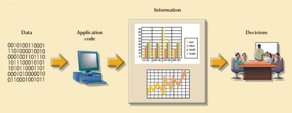
Figure 3.7(I) Generating information for decision making
The performance of information system is depends on three factors such as:
1. Database design and implementation.
2. Application design and implementation.
3. Administrative procedures.
Creating a sound information system is difficult in that systems analysis and development need more planning to ensure that all of the activities will interface with each other, that they will complement each other and completed on time.
The term database development describes the process of database design and implementation. The main objective in database design is to create complete, normalized, non-redundant, and fully integrated conceptual, logical, and physical database models. The implementation phase consist of creating the database storage structure, loading data into the database, and providing for data management.
The procedures which is used to design a small database do not precisely scale up to the procedures that required to design a database for a large corporation. To use an analogy for building a small house needs a blueprint, just as building the Golden Gate Bridge does, but the bridge need more complex and farther-ranging planning, analysis, and design compare with the house.
3.7.1 The Systems Development Life Cycle (SDLC)
The Systems Development Life Cycle (SDLC) is a life cycle of an information system. It is more important to the system designer, the SDLC provides the big picture in which the database design and application development can be mapped out and evaluated.
Figureshows the traditional SDLC which is divided into five phases: planning, analysis, detailed systems design, implementation, and maintenance. The SDLC is an iterative process. For example, the details of the feasibility study help to refine the initial assessment.
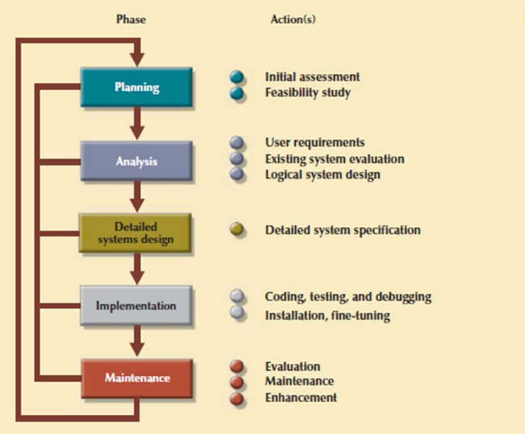
Figure 3.7.1(I)The Systems Development Life Cycle (SDLC)
1. Planning
SYSTEM
1. Planning
The SDLC planning phase represent a general overview of the company and its objectives. An initial assessment of the information flow-and-extent requirements must be made during this discovery portion of the SDLC. Such an assessment should answer some important questions:
Participants in the SDLC’s initial assessment start to study and evaluate another solutions. The feasibility study represent the following:
2. Analysis
Problems defined during the planning phase are examined in details during the analysis phase. A macro analysis is combination of individual needs and organizational needs, addressing questions like:
• What are the wants of the present system’s end users?
• Do those requirements fit into the general information requirements?
The analysis phase of the SDLC is go thorough audit of user needs. The prevailing hardware and software systems are studied during the analysis phase. The results of analysis should be a far better understanding of the system’s functional areas, actual and potential problems, and opportunities. End users and therefore the system designers got to work together to identify processes and to uncover potential problem areas.
For creating a logical design, the designer use tools like data flow diagrams (DFDs), hierarchical input process output diagrams, and entity relationship (ER) diagrams. The database design’s data-modeling activities won’t to discover and describe all entities and therefore the attributes and the relationships among the entities within the database.
3. Detailed Systems Design
In this phase the designer completes the design of the system’s processes. The design consist ofall the technical specifications for the screens, menus, reports, and other devices which is used to make the system a more efficient information generator. The steps are laid out for conversion from the old to the new system. Training principles and methodologies are also planned which is need tosubmit for management’s approval.
4. Implementation
In implementation phase, the hardware, DBMS software, and application programs are installed, and the database design is implemented. At initial stages the system enters into a cycle of coding, testing, and debugging until it is ready to be delivered. The actual database is created, and the system is customized by the creation of tables and views, user authorizations.
The database contents are added interactively or in batch mode, using multiple methods and devices:
The implementation and testing of a new system took 50% to 60% of the total development time. Therefore the advent of sophisticated application generators and debugging tools has decreased coding and testing time. After testing is completed, the final documentation is reviewed and printed and end users are trained.
5. Maintenance
When system is operational then end users begin to request changes in it. Those changes perform system maintenance activities, which is devided into three types:
Because every request for structural change needs retracing the SDLC steps, the system is always at some stage of the SDLC.Every system has a predetermined operational life span. The actual operational life span of a system based on itsperceived utility. There are more reasons for reducing the operational life of certain systems. Rapid technological change is one reason for systems depends on processing speed and expandability.
Another reason is that the cost of maintaining a system. Computer-aided systems engineering (CASE) tools like System Architect or Visio Professional, helps to supply better systems within a low amount of your time and at low cost.
3.7.2 The Database Life Cycle (DBLC)
In larger data system, the database is subject to a life cycle. The Database Life Cycle has six phases that's database initial study, database design, implementation and loading, testing and evaluation, operation as well as maintenance and evolution. Following figure shows DBLC
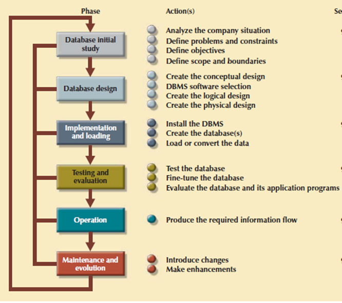
Figure 3.7.2(I)The Database Life Cycle (DBLC)
1. The Database Initial Study
If a designer has been called in, chances are the current system has did not perform functions deemed by the corporate. Additionally to review the current system’s operation within the company, the designer need find how and why the current system fails. That’s spending a longer to talking with end users. Database design may be a technical business and people-oriented. Database designers must be excellent communicators, and finely tuned interpersonal skills.
Based on the complexity and scope of the database environment consist of the database designer could also be one operator or a part of a systems development team composed of a project leader, one or more senior systems analysts, and one or more junior systems analysts. The word designer is employed generically here to hide a wide range of design team compositions. The aim of the database initial study is to:
• Analyze the company situation.
• Define problems and constraints.
• Define objectives.
• Represents scope and limits.
Following figure shows the interactive and iterative processes need to complete the primary phase of the DBLC successfully.
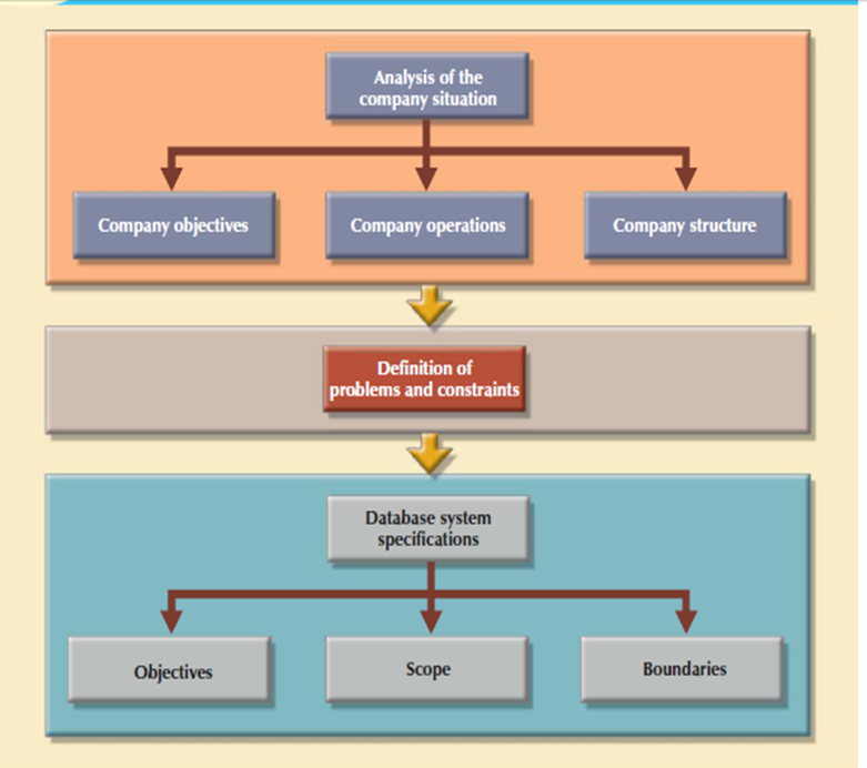
Figure 3.7.2(II)A summary of activities in the database initial study
Analyze the Company Situation
The company situation represents the general conditions in which a company operates, its organizational structure, and its mission. To understand the company situation, the database designer need to identify what the company’s operational components are, how they operate and interact.
These issues need toresolve as:
Define Problems and Constraints
The designer has formal and informal both sources of data. If the company has existed for any length of your time, it already has some kind of system in place. How does the prevailing system function? What input does the system require? What documents does the system generate? By whom and the way is that the system output used?
The process of defining problems might initially present to be unstructured. Company end users aren't ready to describe precisely the larger scope of company operations or to identify the important problems occurred during company operations. The managerial view of a company’s operation and its problems is different from that of the end users, who perform the particular routine work.
Define Objectives
A proposed database system is meant to solve major problems identified within the problem discovery process. In last example, both the marketing manager and therefore the production manager are to be suffering from inventory inefficiencies. The initial objective is to make an efficient inventory query and management system. The designer’s job is to form sure that the database system objectives, as seen by the designer, associated with those envisioned by the top user. In any case, the database designer got to represent the following questions:
• What is that the proposed system’s initial objective?
• Will the system interface with other existing or future systems within the company?
• Will the system share the data with other systems or users?
Represents Scope and limits
The designer need identify the existence of two sets of limits that's scope and limits. The system’s scope defines the extent of the design like operational needs. The designer got to know the “size of the ballpark.” Knowing the scope helps in defining the specified data structures, the type and number of entities, the physical size of the database.
The proposed system is point to limits called as boundaries those are external to the system. Has any designer ever been told, “We have all the time within the world” or “Use a vast budget and use as many of us as needed to form the design come together”? Boundaries also are imposed by existing hardware and software. Ideally, the designer select the hardware and software that fulfill the system goals.
Software selection is an important a part of the Systems Development Life Cycle. Within the real world, a system need to be designed around existing hardware. Thus, the scope and boundaries become the factors that force the design into a selected mold, and therefore the designer’s job is to design the best system possible within those constraints.
2. Database Design
The second phase focuses on the design of the database model that support company operations and objectives. This is often the most critical DBLC phase that making sure that the final product meets user and system requirements. Within the process of database design, you would like to focus on the data characteristics required to create the database model.
There are two views of the data within the system one is that the business view of data as a source of information and other is designer’s view of the data structure, its access, and therefore the activities need to transform the data into information. Following figure shows the various views. Defining data is an integral a part of the DBLC’s second phase. To complete the design introduce the DBLC consider the following points:
• The process of database design is loosely associated with the analysis and design of a bigger system. The data component is only single element of a larger information system. The systems analysts or systems programmers are in charge of designing theother system components. Their activities create the procedures which help to transform the data within the database into useful information.
• The database design doesn't support a sequential process. Rather, it's an iterative process that gives continuous feedback designed to trace previous steps.
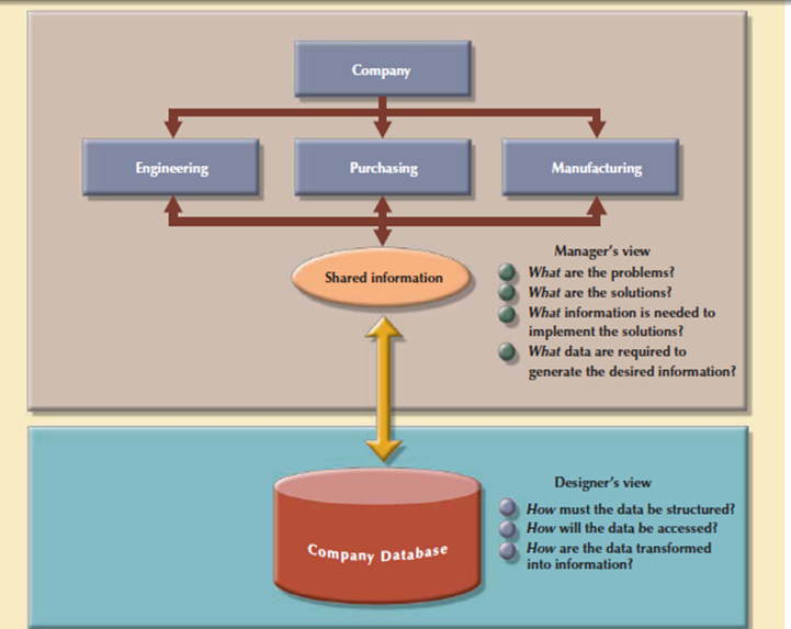
Figure 3.7.2(III)Two views of data: business manager and database designer
The database design process is shown in above Figure. It contains four stages: conceptual, logical, physical design and DBMS selection stage. The design process starts with conceptual design and moves to the logical and physical design stages.
At every stage, more details about the data model design are determined and documented. The conceptual design because the overall data as seen by the end user, the logical design because the data as seen by the DBMS, and therefore the physical design because the data as seen by the operating system’s storage management devices.
It is need to understand that the overwhelming majority of database designs and implementations are depends on the relational model. At the completion of the database design activities, you would like to complete database design able to be implemented.
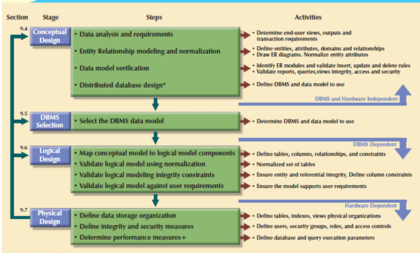
Figure 3.7.2(IV)Database design process
3. Implementation and Loading
The output of the database design phase is a series of instructions describing the creation of tables, attributes, domains, views, indexes, security constraints, and storage and performance guidelines. In this phase you can perform all these design specifications.
Install the DBMS
This step is needed only when a new dedicated instance of the DBMS is necessary for the system. In many cases, the organization will have standardized on a particular DBMS in order to leverage investments in the technology and the skills that employees have already developed. The DBMS is installed on a new server or on existing servers.
Virtualization technique creates logical representations of computing resources that are independent of the physical computing resources. This technique is used in multiple areas of computing like the creation of virtual servers, virtual storage, and virtual private networks. The database virtualization is considered as the installation of a new instance of the DBMSon a virtual server which is running on shared hardware. This task contains system and network administrators to create appropriate user groups and services in the server configuration and network routing.
Create the Databases
In latest relational DBMSs a new database implementation needs the creation of special storage-related constructs to house the end-user tables. The constructs contains the storage group, the table spaces, and the tables. Figure shows the fact that a storage space consist of more than one table space and that a table space can contain more than one table.
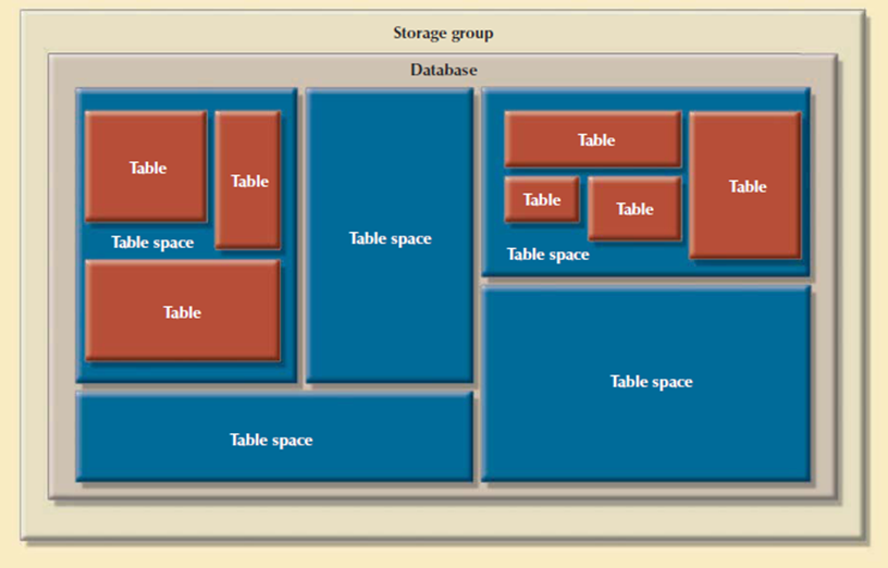
Figure 3.7.2(V)Physical organization of a DB2 database environment
For example, the implementation of the logical design in IBM’s DB2 require that you:
1. Create the database storage group. This step is compulsory for such mainframe databases as DB2. Other DBMS software may create samestorage groups automatically when a database is created. Consult your DBMS documentation to see if you must create a storage group.
2. Create the database within the storage group performed by the SYSADM.
3. Assign the rights to use the database to a database administrator (DBA).
4. Create the table space in the database.
5. Create the table within the table space.
6. Assign access rights to the table spaces and to the tables within specified table spaces.
Access rights are limited to views instead of whole tables. The creation of views is not required for database access in the relational environment. For example, access rights to a table named PROFESSOR granted to the user Shannon Scott whose identification code is SSCOTT with the help ofGRANT SELECT ON PROFESSOR TO USER SSCOTT;
Load or Convert the Data
After creation of database, the information must be loaded into the database tables. There’s need to migrated data from the prior version of the system. The data to be included within the system need to aggregate from multiple sources. During a best-case scenario, all of the data are going to be during a relational database in order that it are often transferred to the new database.
Data are often imported from other relational databases, Non-relational databases, flat files, legacy systems, or from manual paper-and-pencil systems. If the data format doesn't support direct importing into the new database then conversion programs are created to reformat the info in order that it are often imported. During a worst-case scenario, more data are often manually entered into the database. Once the data has been loaded, the DBA works with the application developers to test and evaluate the database.
4. Testing and Evaluation
In the design phase, decisions are taken to make sure integrity, security, performance, and recoverability of the database. During implementation and loading, these plans were put into place. In testing and evaluation, the DBA tests and fine-tunes the database to make sure that it performs for sure. This phase occurs in conjunction with applications programming. Programmers use database tools to prototype the applications during the coding of the programs. Tools like report generators, screen painters, and menu generators are useful to the applications programmers.
Test the Database
In this step the DBA tests the database to identify that it maintains the integrity and security of the data. Data integrity is performed by the DBMS with the assistance of proper use of primary and foreign key rules. Many DBMS support the creation of domain constraints, and database triggers. Testing identify that these constraints were properly designed and implemented. Additionally data integrity is that the results of properly implemented data management policies. These policies are a part of a comprehensive data administration framework.
Previously, users and roles were created to grant users access to the data. During this stage, not only those privileges be tested, but also the broader view of data privacy and security must be addressed. Data stored within the company database need to protect from access by unauthorized users. You would like to check for the following:
Fine-Tune the Database
Database performance is difficult to keep up because there are not any standards for database performance measures, it's the most important factors in database implementation. Different systems will place different performance requirements on the database. Systems to support rapid transactions will need the database to be implemented during a way to provide superior performance in high volumes of inserts, updates, and deletes. Other systems, like decision support systems also need high performance on complex data retrieval tasks.
Multiple factors are impact the database’s performance on various tasks. Environmental factors just like the hardware and software environment during which the database exists, can have a big impact on database performance. The characteristics and volume of the info within the database affect database performance: a search of 10 tuples is quicker than a search of 100,000 tuples. Other important factors in database performance include system and database configuration parameters like data placement, access path definition, the use of indexes, and buffer size.
Evaluate the Database and Its Application Programs
As the database and application programs are created and tested, the system need to evaluate from a more holistic approach. Testing and evaluation of the every components should culminate during a kind of broader system tests to make sure that each one of the components interact properly to satisfy the requirements of the users.
At this point integration issues and deployment plans are refined, user training is conducted, and system documentation is finalized. When the system receives final approval, it's a sustainable resource for the organization. To perform that the info contained within the database are protected against loss, backup and recovery plans are tested.
Timely data availability is crucial for each database. The database are often subject to data loss with the help of unintended data deletion, power outages, and other causes. Data backup and recovery procedures create a security valve, maintain the availability of consistent data. Typically, database vendors supports the use of fault-tolerant components like uninterruptible power supply (UPS) units, RAID storage devices, clustered servers, and data replication technologies to make sure perform continuous operation of the database just in case of a hardware failure.
Some DBMSs provide functions that helps to the database administrator to schedule automatic database backups to permanent storage devices like disks, DVDs, tapes, and online storage. Database backups is performed at multiple levels:
The database backup is stored during a secure place, at a different building from the database itself, and is protected against the fire, theft, flood, and other potential calamities. The main goal of the backup is to ensure database restoration following system failures. Failures that plague databases and systems are contained by software, hardware, programming exemptions, transactions, or external factors. Following figure shows the common sources of database failure.
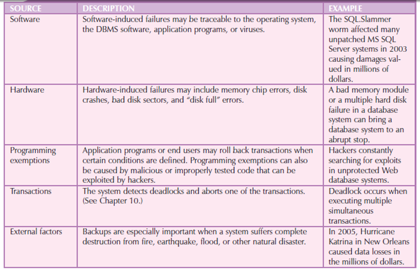
Figure 3.7.2(VI) showsCommon Sources of Database Failure
Based on the type and extent of the failure, the recovery process vary from a minor short-term inconvenience to a significant long-term rebuild. No matter the extent of the specified recovery process it's impossible without a usable backup.
The database recovery process follows a predictable scenario. First, the type and extent of the needed recovery are determine. If the entire database required to be recovered to a uniform state then the recovery uses the recent backup copy of the database during a known consistent state. The backup copy is then rolled forward to revive all subsequent transactions with the help of transaction log information.
If the database required to be recovered but the committed portion of the database still in use then the recovery process uses the transaction log to “undo” all of the transactions that do not committed. At the end the database completes an iterative process of continuous testing, evaluation, and modification that continues until the system is certified as able to enter the operational phase.
5. Operation
After passing the evaluation stage by database, it is considered to be operational. At that point, the database, management, users, and application programs is a complete information system.
The starting of the operational phase invariably starts the process of system evolution. In that all of the targeted end users have entered the operations phase. Some of the problems are serious to warrant emergency “patchwork,” For example, if the database design is implemented to interface with the Web, the sheer volume of transactions may cause even a well-designed system to be down.
6. Maintenance and Evolution
The database administrator prepared to perform routine maintenance activities in the database. Some of the needed periodic maintenance activities contains:
The new information needs and the demand for additional reports and new query formats needapplication changes and minor changes in the database components and contents. Those changes applied only when the database design is flexible and when all documents is updated and online.The best-designed database environment will no longer be capable of incorporating such evolutionary changes and then the whole DBLC process begins anew.
Following figure shows the summary of the parallel activities in SDLC and the DBLC.
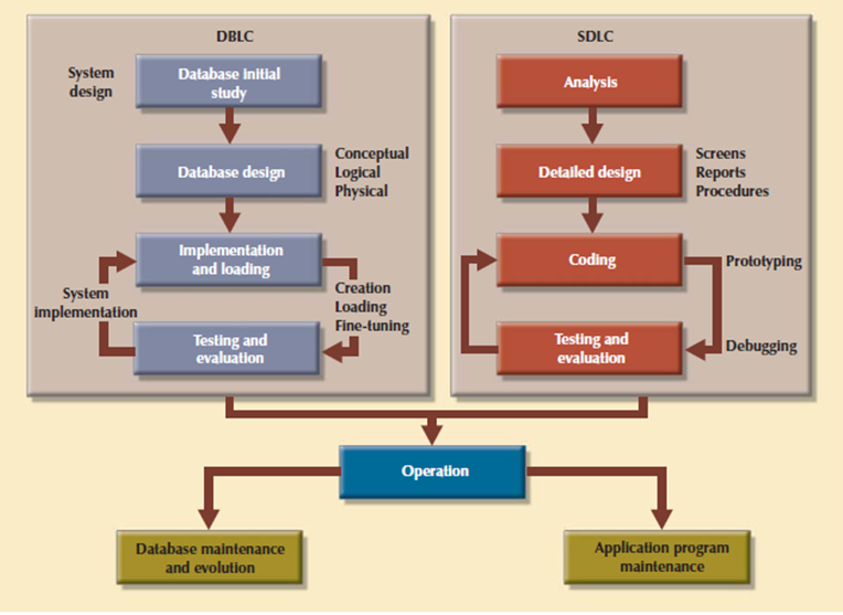
Figure 3.7.2(VII)Parallel activities in the DBLC and the SDLC
Conceptual Design
The second phase of the DBLC is database design, and its four stages: conceptual design, DBMS selection, logical design, and physical design. Conceptual design is that the first stage in the database design process. The goal of this stage is to design a database that's not dependent on database software and physical details. The output of this process may be a conceptual data model which explains the most data entities, attributes, relationships, and constraints of a given problem domain. This design is descriptive and narrative in form. It made up of a graphical representation and textual descriptions of the data elements, relationships, and constraints.
In this stage, data modeling is used to make an abstract database structure which describe real-world objects within the most realistic way possible. At this level of abstraction, the type of hardware and database model used not identified yet. Therefore, the design must be software and hardware independent therefore the system are often set up in any hardware and software platform selected.
Consider the following minimal data rule:
All that is needed is there, and all that is there is needed.
That means confirm that all data needed are in the model and that all data in the model are needed. All data elements required by the database transactions need todefine in the model, and all data elements defined in the model must be used by at least one database transaction.
When you apply the minimal data rule then avoid an excessive short-term bias. Focus on the immediate data needs of the business and the future data needs.
The conceptual design contains four steps.
1. Data Analysis and Requirements
This step is used to discover the characteristics of the data elements. An effective database is an information factory that produces key ingredients for successful decision making. Appropriate data element characteristics are those that can be transformed into appropriate information. The designer’s efforts are focused on:
The designer get the answers to those questions from a multiple sources in to compile the necessary information. Consider sources are:
Developing and gathering end-user data views.
The database designer and end users interact to jointly develop a particular description of end-user data views. The end-user data views are used to help find out the database’s main data elements.
Directly observing the current system: existing and desired output.
The end user has an existing system in place, whether it’s manual or computer-based. The designer reviews the existing system to find outthe data and their characteristics. The designer identify the input forms and files to discover the data type and volume. If the end user already has an automated system then the designer carefully examines the current and desired reports to show the data need to support the reports.
Interfacing with the systems design group.
The database design process is a component of the Systems Development Life Cycle (SDLC). Sometimes the systems analyst responsible of designing the new system also will develop the conceptual database model. In other cases, the database design is considered a part of the database administrator’s job. The presence of a database administrator that's DBA implies the existence of a proper data-processing department. The DBA designs the database with reference to the specifications created by the systems analyst.
To develop an accurate data model, the designer need to understand the company’s data types and their extent and uses. But data don't yield the specified understanding of the entire business. From a database point of view, the collection of data is meaningful only business rules are defined.
Business rules are easy to know and that they must be widely disseminated to make sure that each person within the organization shares a common interpretation of the principles. Using simple language, business rules describe the main characteristics of the data as viewed by the company. Samples of business rules are as follows:
The business rules are derived from a formal description of operations, which can be a document that gives an exact, up-to-date description of the activities that define an organization’s operating environment.
An organization’s operating environment is predicated on the organization’s mission. Forinstance, the operating environment of a university is different from that of a steel manufacturer, an airline, or a nursing home. Therefore matter how different the organizations could also be , the data analysis and requirements component of the database design process is enhanced when the data environment and data use are described accurately and precisely within a description of operations.
In a business environment, the most sources of data for the description of operations and therefore the business rules are company managers, policy makers, department managers, and written documentation like company procedures, standards, and operations manuals. A faster and more direct source of business rules is direct interviews with end users.
For example, a maintenance department mechanic believe that any mechanic can initiate a maintenance procedure, when actually only mechanics with inspection authorization should perform a task. Such a distinction is difficult but its major legal consequences. End users are crucial contributors to the development of business rules, it pays to verify end-user perceptions. Often interviews with many people that perform an equivalent job yield very different perceptions of their job components.
Understanding the business rules helps the designer to understand how the business works and what role the data plays within company operations. The designer must identify the company’s business rules and analyze their impact on the character, role, and scope of knowledge.
Business rules provides multiple important benefits within the design of latest systems:
The last point is especially noteworthy: whether a given relationship is mandatory or optional is usually a function of the applicable business rule.
2. Entity Relationship Modeling and Normalization
Before creating the ER model, the designer need to communicate and manage appropriate standards utilized in the documentation of the design. The standards contains the utilization of diagrams and symbols, documentation writing style, layout, and the other conventions which is followed during documentation. Designers often overlook this vital requirement, once they are working as members of a design team. Failure to standardize documentation means a failure to communicate later, and communications failures often cause poor design work. In contrast, well-defined and enforced standards make design work easier and promise a smooth integration of all system components.
Because the business rules define the nature of the relationship between the entities, the designer need to incorporate them into the conceptual model. The method of defining business rules and developing the conceptual model using ER diagrams is described using the following steps
TIVITY
Some of the above steps performed concurrently. And a few just like the normalization process, can generate a requirement for extra entities or attributes, thereby causing the designer to revise the ER model. For example, while identifying two main entities, the designer may additionally identify the composite bridge entity that represents the many-to-many relationship between those two main entities.
To review consider that you simply are creating a conceptual model for the JollyGood Movie Rental Corporation, whose end users want to trace customers movie rentals. The simple ER diagram shown in Figure shows a composite entity that helps track customers and their video rentals. Business rules define the optional nature of the relationships between the entities VIDEO and CUSTOMER. Consider the composite RENTAL entity that connects the 2 main entities.

Figure 3.7.2(VIII)JollyGood Movie Rental ER
The initial ER model supported too many revisions before it meets the system’s requirements. Such a revision process may be a natural. Remember that the ER model may be a communications tool and also a design blueprint. Therefore, once you meet with the proposed system users, the initial ER model should give rise to questions like, “Is this really what you meant?”
Clearly all attributes need defined and therefore the dependencies must be checked before the design are often implemented. Additionally, the design cannot support the standard video rental transaction environment. For example, each video is probably going to possess many copies available for rental purposes. However, if the VIDEO entity won’t to store the titles and therefore the copies, the design triggers the data redundancies.
VIDEO_DAYS

The initial ERD must be modified to reflect the answer to the question, “Is more than one copy available for each title?” Also, payment transactions can be supported.
ER modeling activities take place in a particular sequence. In fact, once you have completed the initial ER model there is chances to move back and forth among the activities until you are satisfied that the ER model accurately shows a database design that is capable of meeting the required system demands. The activities performed in parallel, and the process is iterative.
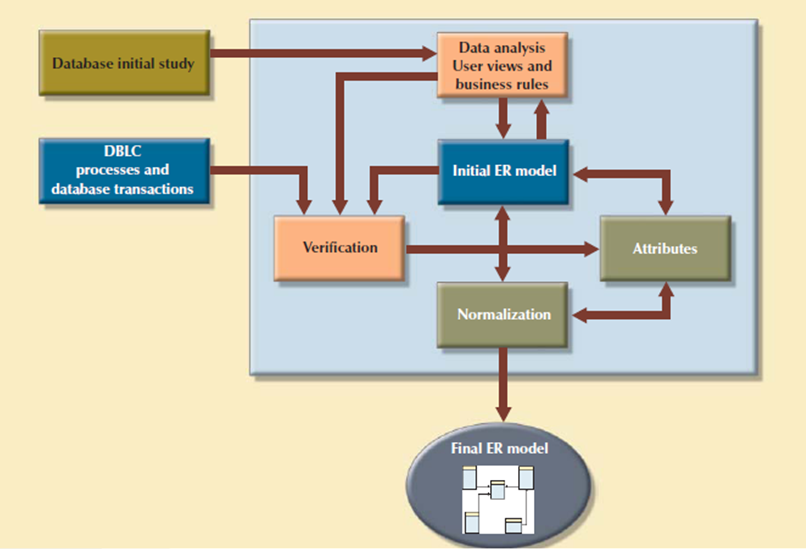
Figure 3.7.2(IX)ER modeling is an iterative process based on many activities
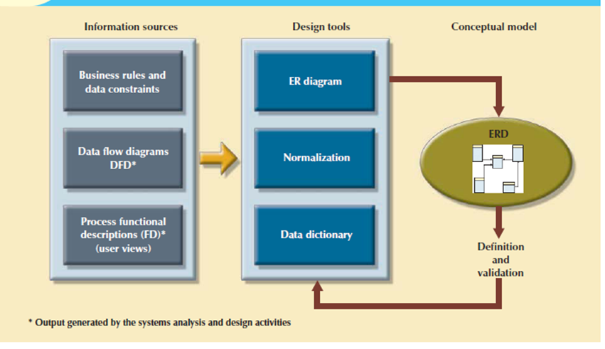
Figure 3.7.2(X) Conceptual design tools and information sources
All objects are defined during a data dictionary, which is used with the normalization process to assist remove data anomalies and redundancy problems. During this ER modeling process, the designer is:
• Define entities, attributes, primary keys, and foreign keys.
• Make decisions for adding new primary key attributes to satisfy end-user and processing requirements.
• Make decisions about the treatment of composite and multivalued attributes.
• Make decisions about adding derived attributes to fulfill the processing requirements.
• Take the choices about the location of foreign keys in 1:1 relationships.
• Avoid unnecessary ternary relationships.
• Draw the corresponding ER diagram.
• Normalize the entities.
• Include all data element definitions within the data dictionary.
• Make decisions about standard naming conventions.
The naming conventions requirement is vital and it's ignored at the designer’s risk. Real database design is completed by teams. Therefore, it's important to make sure that the team members work in an environment during which naming standards are defined and enforced. Proper documentation is need to the successful completion of the design.
3. Data Model Verification
The data model verification step is one of the last steps in the conceptual design stage, and most critical also. In this step, the ER model verified against the proposed system processes in order to corroborate that the intended processes can be supported by the database model. Verification needs the model be run through a series of tests against:
Because real-world database design is done by teams, it is very likely the database design is divided into several components called as modules. A module is an information system component used to handles some business function like inventory, orders, and payroll. In these conditions every module is supported by an ER segment that's a subset of an enterprise ER model. Working with modules accomplishes many important ends:
• The modules are often delegated to design groups within teams, speeding up the development work.
• The modules simplify the design work. The greater number of entities within a complex design are often daunting.
• Every module contains a many manageable number of entities.
• The modules are prototyped quickly. Implementation and applications programming trouble spots are often identified more readily.
• Even if the whole system can’t be brought online quickly, the implementation of 1 or more modules will shows that progress is being made which a minimum of a part of the system is prepared to begin serving the end users.
Following are fragments of ER model:
• Might present overlapping, duplicated or conflicting views of an equivalent data.
• Might not be ready to support all system’s modules processes.
The problems solution is that the modules ER fragments are merged into one enterprise ER model. This process starts by selecting a central ER model segment and iteratively adding additional ER model segments one at a time. At every stage, for every new entity added to the model, required to validate that the new entity doesn’t overlap or conflict with a previously identified entity within the enterprise ER model.
Merging the ER model segments into an enterprise ER model triggers a careful reevaluation of the entities, followed by an in depth examination of the attributes that represents those entities. This process is used for multiple important purposes:
• The emergence of the attribute details cause a revision of the entities themselves.
• The focus on attribute details can provide clues about the nature of relationships as they're defined by the primary and foreign keys. Improperly defined relationships lead to implementation problems first and to application development problems later.
• To satisfy processing or end-user requirements, it'd be useful to make a new primary key to exchange an existing primary key.
A surrogate primary key might be introduced to replace the original primary key composed of VIDEO_ID and CUST_NUMBER.
Unless the entity details are precisely defined, it is difficult to evaluatethe extent of the design’s normalization. Knowledge of the normalization levels helps guard against undesirable redundancies.
A careful review of the rough database design blueprint is probably going to lead to revisions. Those revisions will help make sure that the design is capable of meeting end-user requirements.
After finishing the merging process the enterprise ER model is verified against every modules processes. Following is the ER model verification process. Process
STEP ACTIVITY
- Internal: Updates/Inserts/Deletes/Queries/Reports
- External: Module interfaces
Consider that the verification process needs the continuous verification of business transactions also system and user requirements. The verification sequence must be repeated for every system’s modules. Figure shows the iterative nature of the process.
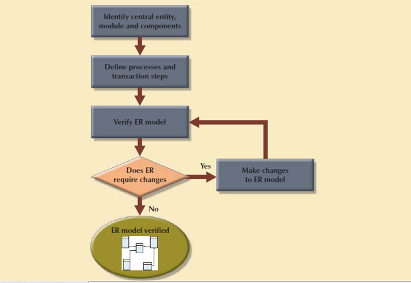
Figure 3.7.2(XI)Iterative ER model verification process
The verification process starts with selecting the central entity. The central entity is defined in terms of its participation in most of the model’s relationships, and it's the main target for many of the system’s operations. In other words, to identify the central entity, the designer selects the entity involved within the greatest number of relationships. Within the ER diagram, it's the entity with more lines connected to it than the other.
The next step is to identify the module or subsystem to which the central entity belongs and to define that module’s boundaries and scope. The entity belongs to the module that uses it most often. Once every module is identified, the central entity is placed within the module’s framework to focus your attention on the module’s details.
Within the central entity/module framework, you need to:
Processes is classified according to their:
All identified processes need to verified against the ER model. If necessary, appropriate changes are implemented. The process verification is repeated for all of the model’s modules. You’ll expect that additional entities and attributes are going to be incorporated into the conceptual model in its validation.
4. Distributed Database Design
Sometimes a database may have to be distributed between multiple geographically disperse locations. Processes that access the database may is vary from one location to a different. For example, a retail process and a warehouse storage process are to be found in several physical locations. If the database data and processes are to be distributed across the system, portions of a database, called as database fragments, present at several physical locations.
A database fragment may be a subset of a database that's stored at a given location. The database fragment could also be composed of a subset of rows or columns from one or many tables. Distributed database design defines the optimum allocation strategy for database fragments so as to make sure database integrity, security, and performance. The allocation strategy determines the way to partition the database and where to store each fragment.
The selection of DBMS software is critical to the information system’s smooth operation. The benefits and drawbacks of the proposed DBMS software should be carefully studied. To avoid false expectations, the end user must be made aware of the restrictions of both the DBMS and therefore the database. Although the factors affecting the purchasing decision vary from company to company, some of the most common are:
Logical Design
Logical design is that the second stage within the database design process. The logical design goal is to style an enterprise-wide database based on a selected data model but independent of physical-level details. Logical design requires that each one objects within the conceptual model be mapped to the precise constructs used by the chosen database model. For example, the logical design for a relational databasecontains the specifications for the relations, relationships, and constraints. The logical design is worked in four steps, which are shown as following. Steps
STEP ACTIVITY
1. Mapping the Conceptual Model to the Logical Model
The first step in creating the logical design is to map the conceptual model to the chosen database constructs. Within the world, logical design present at translating the ER model into a group of relations, columns, and constraints definitions. The process of translating the conceptual model into a group of relations is shown as follows.
ITY
A strong entity is one that present at 1 side of all its relationships, that is, an entity that doesn't have any mandatory attribute that's a foreign key to a different table. Therefore, the first entities to be translated into tables would be the employee and COURSE entities. During this case, you define what would be the table name, what would be its columns and their characteristics. Forinstance, the relation definitions for the strong entities on SimpleCollege can be:
COURSE (CRS_CODE, CRS_TITLE, CRS_DESCRIPT, CRS_CREDIT) PRIMARY KEY: CRS_CODE
EMPLOYEE (EMP_NUM, EMP_LNAME, EMP_FNAME, EMP_INITIAL, EMP_E_MAIL)
PRIMARY KEY: EMP_NUM
Once all strong entities are mapped, you're able to map any entities involved during a supertype/subtype relationship or any weak entities. Within the case of SimpleCollege, you have the PROFESSOR entity that's a subtype of the employee entity. PROFESSOR is additionally a weak entity because it inherits its primary key from EMPLOYEE and it's existence-dependent on EMPLOYEE. At this point, you furthermore may start defining the relationships between supertype and subtype entities. For example:
PROFESSOR (EMP_NUM, PROF_SPECIALTY, PROF_RANK) PRIMARY KEY: EMP_NUM FOREIGN KEY: EMP_NUM REFERENCES PROFESSOR
Next, you start mapping all binary relationships. In the previous example you have defined the Supertype/subtype relationship between EMPLOYEE and PROFESSOR. This is an instance that shown the iterative nature of this process. Continuing with the SimpleCollege ER model define the CLASS relation and define its 1: M relationships with PROFESSOR and COURSE:
CLASS (CLASS_CODE, EMP_NUM, CLASS_TIME, CLASS_DAYS, CRS_CODE)
PRIMARY KEY: CLASS_CODE FOREIGN KEYS: EMP_NUM REFERENCES PROFESSOR
CRS_CODE REFERENCES COURSE
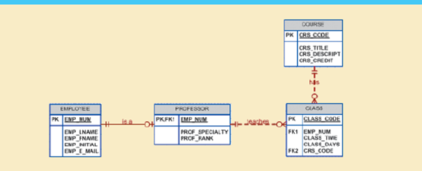
Figure 3.8(I) showsThe SimpleCollege conceptual model
The logical design’s tables must correspond to the entities shown within the conceptual design, and therefore the table columns must correspond to the attributes laid out in the conceptual design. The ultimate outcome of this process may be a list of relations, attributes, and relationships which will be the basis for future step.
2. Validate the Logical Model with the help of Normalization
The logical design contain only properly normalized tables. The method of mapping the conceptual model to the logical model may unveil some new attributes or the invention of latest multivalued or composite attributes. Therefore, it’s very likely that new attributes could also be added to tables or entire new tables added to the logical model. For every identified table, you want to make sure that all attributes are fully dependent on the identified primary key which the tables are in at least third normal form (3NF).
As indicated the database design is an iterative process. Activities like normalization happen at different stages within the design process. Whenever you reiterate a step, the model is further refined and better documented. New attributes could also be created and assigned to the proper entities. Functional dependencies among determinant and dependent attributes are evaluated and data anomalies are prevented through normalization.
3. Validate Logical Model Integrity Constraints
The translation of the conceptual model into a logical model needs the definition of the attribute domains and appropriate constraints. For example, the domain definitions for the CLASS_CODE, CLASS_DAYS, and CLASS_TIME attributes displayed within the CLASS entity are written in following way:
CLASS_CODE is a valid class code.
Type: numeric
Range: low value = 1000 high value = 9999
Display format: 9999
Length: 4
CLASS_DAYS is a valid day code.
Type: character
Display format: XXX
Valid entries: MWF, TTh, M, T, W, Th, F, S
Length: 3
CLASS_TIME is a valid time.
Type: character
Display format: 99:99 (24-hour clock)
Display range: 06:00 to 22:00
Length: 5
All those defined constraints must be supported by the logical data model. During this stage, you want to map all those constraints to the proper relational model constraints. Forinstance, the CLASS_DAYS attribute is character data that should be restricted to a list of valid character combinations. Here, you define that this attribute will have a check in constraint to enforce that the only allowed values are “MWF”, “TR”, “M”, “T”, “W”, “”R”, “F”, and “S”. During this step, you may define which attributes are necessary and which are optional and make sure that all entities maintain entity and referential integrity.
The right to use the database is additionally specified during the logical design phase. Who are going to be allowed to use the tables and what portion of the table are going to be available to which users? For solution consider following view.
CREATE VIEW SCHEDULE AS SELECT EMP_FNAME, EMP_LNAME, CLASS_CODE, CRS_TILE, CLASS_TIME, CLASS_DAYS FROM PROFESSOR, CLASS, COURSE WHERE PROFESSOR.EMP_NUM = CLASS.EMP_NUM AND CLASS.CRS_CODE = COURSE.CRS_CODE
4. Validate the Logical Model against User Requirements
The logical design convert the software independent model in a software dependent model. The final step within the logical design process is to validate all logical model definitions against all end-user data, transaction, and security requirements. A process almost like the one shown in Table takes place again to make sure the correctness of the logical model. The stage define the physical requirements that allow the system to function within the chosen DBMS/hardware environment.
Physical Design
Physical design is that the process of determining the data storage organization and data access characteristics of the database in order to make sure its integrity, security, and performance. This is often the last stage within the database design process. The storage characteristics are a function of the kinds of devices supported by the hardware, the type of data access methods supported by the system, and therefore the DBMS. Physical design are often technical job that affects not only the accessibility of the data within the storage device but also the performance of the system.
The physical design stage is composed of the following steps.
ACTIVITY
1. Define Data Storage Organization
Before you can define the data storage organization, you need find the volume of data to be managed and thedata usage patterns.
• Knowing the data volume will assist you determine how much space for storing to reserve for the database. The designer follows a process almost like the one used during the ER model verification process. For every table, identify all possible transactions, their frequency, and volume. For every transaction, you identify the amount of data to be added or deleted from the database. This information will assist you determine the quantity of data to be stored within the related table.
• Conversely, knowing how frequently the new data is inserted, updated, and retrieved will help the designer to determine the data usage patterns. Usage patterns are critical, especially in distributed database design. For example, are there any weekly batch uploads or monthly aggregation reports to be generated? How frequently is new data added to the system?
Equipped with the 2 previous pieces of information, the designer must:
Determine the location and physical storage organization for each table.
Tables are stored in table spaces and a table space can hold data from multiple tables. During this step the designer assigns which tables will use what table spaces and therefore the location of the table spaces. Forinstance, a useful technique available in most relational databases is that the use of clustered tables. The clustered table’s storage technique stores related rows from two related tables in adjacent data blocks on disk. This ensures that the data are stored in sequentially adjacent locations, thereby reducing data time interval and increasing system performance.
Identify what indexes and the type of indexes to be used for each table.
Indexes are useful for ensuring the uniqueness of data values during a column and to facilitate data lookups. You furthermore may know that the DBMS automatically creates a unique index for the primary key of every table. At this point, you identify all required indexes and determine the best type of organization to use supported the data usage patterns and performance requirements.
Identify what views and the type of views to be used on each table.
A view is beneficial to limit access to data supported user or transaction needs. Views also can be used to simplify processing and end-user data access. During this step the designer must make sure that all views are often implemented which they supply only the specified data. At this point, the designer must also get familiar with the kinds of views supported by the DBMS and the way those types of views could help meet system goals.
2. Define Integrity and Security Measures
Once the physical organization of the tables, indexes, and views are defined, the database is prepared to be used by the end users. But before a user can access the information within the database, he or she must be properly authenticated. During this step of physical design, two tasks must be addressed:
Define user and security groups and roles.
User management is more a function of database administration than database design. But, as a designer you want to remember of the various types of users and group of users so as to properly enforce database security. Most DBMS implementations support the use of database roles. A database role may be a set of database privileges that would be assigned as a unit to a user or group. For example you'll define an Advisor role that has Read access to the vSCHEDULE view.
Assign security controls.
The DBMS supports administrators to assign specific access rights on database objects to a user or group of users. As an example, you'll assign the SELECT and UPDATE access rights to the user sscott on the class table. An access right could even be revoked from a selected user or groups of users. This feature could are available handy during database backups or scheduled maintenance events.
3. Determine Performance Measures
Physical design are more complex when data are distributed at different locations because the performance is suffering from the communication media’s throughput. Considering these it's not surprising that designers favor database software that hides as many of the physical-level activities as possible. In spite of the very fact that relational models tend to hide the complexities of the computer’s physical characteristics, the performance of relational databases is suffering from physical storage characteristics.
For example, performance are often affected by the characteristics of the storage media, like seek time, sector and block size, buffer pool size, and therefore the number of disk platters and read/write heads. Additionally, factors like the creation of an index contains substantial effect on the relational database’s performance such as data access speed and efficiency.
Physical design performance measurement deals with fine-tuning the DBMS and queries to make sure that they're going to meet end-user performance requirements. The preceding sections have separated the discussions of logical and physical design activities. In fact, logical and physical design are often performed in parallel, on a table-by-table basis. Such parallel activities need the designer to have a thorough understanding of the software and hardware so as to require full advantage of both software and hardware characteristics.
3.8.1 Database Design Strategies
There are two classical approaches to database design:
1. Top-down designstarts by identifying the data sets and then defines the data elements for each of those sets.
This process involves the identification of different entity types and the definition of each entity’s attributes.
2. Bottom-up designfirst identifies the data elements and then groups them together in data sets. In other words, it first defines attributes, and then groups them to form entities.
The two approaches are shown in figure. The choice of a primary supported top-down or bottom-up procedures often depends on the scope of the problem or on personal preferences. Although the 2 methodologies are complementary instead of mutually exclusive, a primary emphasis on a bottom-up approach could also be more productive for little databases with few entities, attributes, relations, and transactions.
The situations in which the number, variety, and complexity of entities, relations, and transactions is overwhelming, a primarily top-down approach could also be more easily managed. Many companies have standards for systems development and database design already in place.
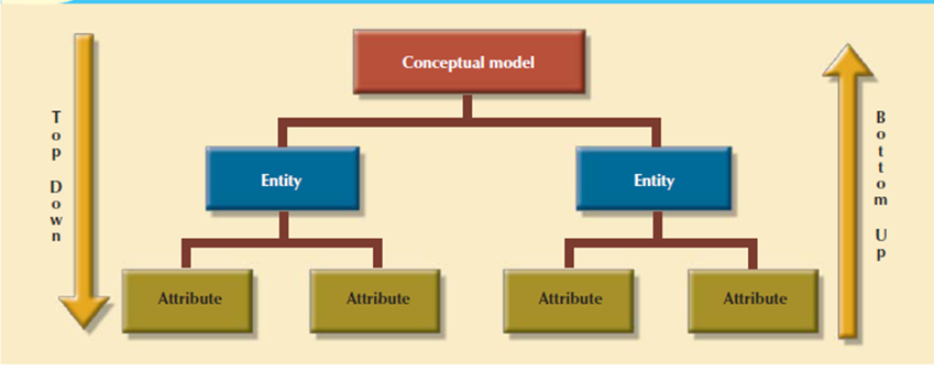
Figure 3.8.1(I)Top-down vs. bottom-up design sequencing
3.8.2 Centralized Vs. Decentralized Design
The two general approaches like bottom-up and top-down to database design are often influenced by factors like the scope and size of the system, the company’s management style, and therefore the company’s structure that's centralized or decentralized. Depending on such factors, the database design could also be supported two very different design philosophies: centralized and decentralized.
1. Centralized designis productive when the data component consists of a comparatively small number of objects and procedures. The design are carried out and represented during a fairly simple database. Centralized design is typical of relatively simple and/or small databases and may be successfully done by one person or by a little, informal design team.
The company operations and scope of the problem are limited to allow even a single designer to define the problem, create the conceptual design, verify the conceptual design with the user views, define system processes and data constraints to make sure the efficacy of the design, and make sure that the design will suits all the requirements. Following figure shows the centralized design architecture. A single conceptual design is completed and validated within the centralized design approach.
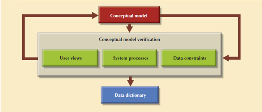
Figure 3.8.2(I)Centralized design
Conceptual
2. Decentralized designused when the data component of the system features a number of entities and complex relations on which very complex operations are performed. Decentralized design is used when the problem itself is spread across several operational sites and every element is a subset of the whole data set.
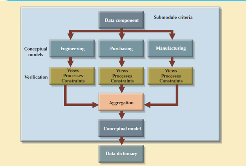
Figure 3.8.2(II)Decentralized design
In large and complicated projects, the database design can't be done by just one person. Instead, a carefully selected team of database designers is used to find a complex database project. Within the decentralized design framework, the database design task is split into several modules. Once the design criteria is formed, the lead designer assigns design subsets or modules to design groups within the team.
Because each design group focuses on modeling a subset of the system, the definition of boundaries and therefore the interrelation among data subsets is very precise. Each design group creates a conceptual data model like the subset being modeled. Each conceptual model is then verified individually against the user views, processes, and constraints for every of the modules. After the verification process has been completed, all modules are integrated into one conceptual model.
Because the data dictionary shows the characteristics of all objects within the conceptual data model, it has an important role within the integration process. The subsets are aggregated into a bigger conceptual model, the lead designer need to verify that the combined conceptual model is ready to support all of the specified transactions. The aggregation process needs the designer to make one model during which many aggregation problems need toaddress.
Reference Text Book
Reference links