Unit 2
Communication and Synchronization
Communication
Inter-process communication is that the heart of all distributed systems. It makes no sense to review distributed systems without carefully examining the ways in which processes on different machines can exchange information.
Communication in distributed systems is often supported low-level message passing as offered by the underlying network.
In distributed systems when messages are exchanged between processes the access transparency problem is occurred while sending and receiving the messages.
In a nutshell, the Birrell and Nelson suggested that allowing programs to call procedures located on other machines. When a procedure on machine A calls' a procedure on machine B. If the calling process on A is suspended then execution of the called procedure takes place on B.
Information are often transported from the caller to the callee within the parameters and can come back in the procedure result. No message passing in any respect is visible to the programmer. This method is known as Remote Procedure Call, or simply RPC.
Basic RPC operation
We first start with conventional procedure calls, so how the call itself can be split into a client and server part that are each executed on different machines.
Conventional Procedure Call
To understand RPC study of Conventional Procedure call is very important. Consider the call in C
Count=tead(fd,buff,nbytes);
Where fd is an integer file, buff is an array of characters into which data are read, and nbytes is another integer telling what percentage bytes to read.
If the call is made from the main program, the stack are as shown in Fig. 2.1(a) before the call. To make the call, the caller pushes the parameters onto the stack so as, last one first, as shown in Fig. 2.1(b).
After the read procedure has finished running, it puts the return value in an exceedingly register, removes the return address, and transfers control back to the caller. The caller then removes the parameters from the stack, returning the stack to the first state it had before the call.
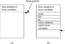
Fig 2.1 (a) shows parameter passing in a local procedure call before the stack call to read. (b) The stack when the called procedure is active.
In C there are two ways of passing parameters call by value or call by reference.A value parameter, which is fd or nbytes, is simply copied to the stack as shown in Fig. 2.1(b).
To the called procedure, a value parameter as simply an initialized local variable. The called procedure may modify it, but such changes don’t affect the original value at the calling side.
A reference parameter in C could be a pointer to a variable (i.e., the address of the variable), instead of the value of the variable. Within the call to read the second parameter could be a reference parameter because arrays are always passed by reference in C.
What is actually pushed onto the stack is that the address of the character array. If the called procedure uses this parameter to store something into the character array, it does modify the array within the calling procedure.
Client and Server Stubs
The main purpose of RPC is to be transparent, the calling procedure shouldn’t remember that the called procedure is executing on a different machine or the other way around.
For example if program must needs to read some data from a file. The programmer puts a call to read within the code to get the data.
In a traditional way single-processor system, the read routine is extracted from the library by the linker and inserted it into the object program. It’s a short procedure, which is mostly implemented by calling an analogous read call.
RPC achieves its transparency during a similar way. When read is truly a remote procedure, a unique version of read, called a client stub, is put into the library.
Following figure shows the Remote Procedure Call between client and server program.
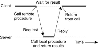
Fig 2.1 (c ) Working of RPC between a client and server program.
Following the call to send, the client stub calls receive subsequently block itself until the reply comes back. When the message arrives at the server, the server's operating system send it to a server stub. A server stub is that the server-side equivalent of a client stub: it’s a small code that transforms requests coming in over the network into local procedure calls.
A remote procedure call occurs within the next steps:
- The client procedure calls the client stub within the traditional way.
- The client stub builds a message and calls the local operating system.
- The client's as sends the message to the remote as.
- The remote as gives the message to the server stub.
- The server stub unpacks the parameters and calls the server.
- The server does the work and returns the result to the stub.
- The server stub packs during a very message and calls its local as.
- The server's as sends the message to the client's as.
- The client's as gives the message to the client stub.
- The stub unpacks the result and returns to the client.
Parameter Passing
The function of the client stub is to want its parameters, pack them into a message, and send them to the server stub. There are two ways of parameter passing value parameter and reference parameter.
- Passing value parameter
Packing parameters into a message is known parameter marshaling. Consider the easy example there’s add(i,j) procedure for addition of two numbers and it returns the sum.
Following figure shows the call to add procedure. The client stub takes its two parameters and form them in a message. It also puts the name or number of the procedure to be called within the message because the server might support multiple different calls, and it has to be told which one is required.
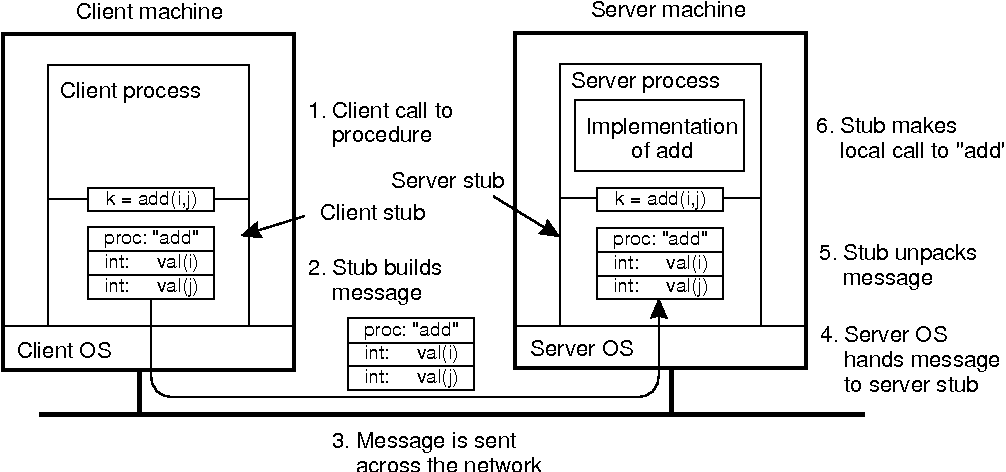
Figure 2.1 (d) the steps involved in a performing a remote computation through RPC.
When the message arrives at the server that point stub examines the message to determine which procedure is required then makes the acceptable call. If the server also supports other remote procedures, the server stub might need a switch statement in it to select the procedure to be called, looking on the primary field of the message.
The particular call from the stub to the server looks like the original client call, except that the parameters are variables initialized from the incoming message.
When the server has finished its task the server stub gains control again. It takes the result sent back by the server and formed a message. The message is sent back to the client stub. Which unpacks it and extract the result and returns the value to the waiting client procedure.
B. Passing reference parameter
Pointer is refer as address is meaningful only within the address space of the process in which it is being used. One solution is simply to forbid pointers and reference parameters in generally.
However, these are so important that this solution is extremely undesirable. The client stub knows that the second parameter points to an array of characters required for perform operation. It is also knows how big the array is. One strategy then becomes present to copy the array into the message and send it to the server.
The server stub can then call the server with a pointer to the present array, although this pointer contains a special numerical value than the second parameter of read has. Changes the server makes using the pointer points to the message buffer inside the server stub. When the server finishes, the first message is sent back to the client stub, which then copies it back to the client. Sometimes Call-by-reference has been replaced by copy/restore.
Asynchronous RPC
In conventional procedure calls, when a client calls a remote procedure, the client will block until a reply is returned from the server. This strict request-reply behavior isn’t necessary when there’s no result to return, and only ends up in blocking the client while it could have proceeded and have done useful work just after requesting the remote procedure to be called.
Examples of where there’s often not required to waiting for a reply include which includes transferring money from one account to a different, adding entries into a database, starting remote services, batch processing, and many more.
To support such situations, RPC systems may provide facilities for what are called asynchronous RPCs, by which a client immediately continues after issuing the RPC request. With asynchronous RPCs, the server immediately sends a reply back to the client at the time RPC request is received, after which it calls the requested procedure.
The reply sends an acknowledgment to the client that the server goes to process the RPC. The client will continue without further blocking as soon because it has received the server's acknowledgment.
Following fig shows how client and server interact within the case of asynchronous RPCs.

(e) (f)
Fig 1.1 (e) the figure shows interaction between client and server in a traditional RPC and fig.(f) Shows the interaction using asynchronous RPC.
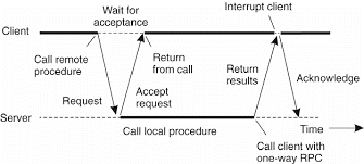
Fig 2.1 (g) A client and server interacting through two asynchronous RPCs.
Asynchronous RPCs can also can be useful when a reply going tobe returned but the client isn’t prepared to wait for it and do nothing within the meantime. As an example, a client might want to pre-fetch the network addresses of a collection of hosts that it expects to contact soon.
While a naming service is collecting those addresses, the client might want to do other things. In such cases, it makes sense to organize the communication between the client and server through two asynchronous RPCs, as shown in Fig. 2.1(g).
Example: DCE RPC
The Distributed Computing Environment (DeE) RPC system, which was developed by the Open Software Foundation (OSF), now called The Open Group.
Introduction to DCE
DCE is a truly middleware system. This system is designed to execute as a layer of abstraction between existing (network) operating systems and distributed applications. It is designed for UNIX, it has now been ported to all major operating systems including VMS and different Windows platforms, as well as desktop operating systems.
The idea is that the customer can take a set of existing machines and therein that add the DCE software, and then it will be ready to run distributed applications without disturbing existing (non-distributed) applications.
There are a variety of different services that form a part of DCE itself. The distributed file service may be a worldwide file system which provides a transparent way of accessing any file in the system within the same way.
Goals of DCE RPC
The DCE RPC system provides the relatively traditional goals to the system.The RPC system easy for a client to access a remote service by simply calling a local procedure.
This interface makes it possible for client programs to be written in a very simple way which is known to most programmers. It also provides the facility for large volumes of existing code run in a distributed environment.
The RPC systems are hide all the details from the clients, and, to some extent, from the servers also start out with, the RPC system can automatically locate the suitable server, and subsequently founded the communication between client and server software called as binding.
It can even handle the message transport in both directions, fragmenting and reassembling them as required. Finally, the RPC system can automatically handle data type conversions between the client and also the server, whether or not they run on different architectures and have a unique byte ordering.
Writing a Client and a Server
The DCE RPC system consists of a range of components, including languages, libraries, daemons, and utility programs, among others. Together these make it possible to write down clients and servers.
The entire process of writing and using an RPC client and server is summarized in Fig. 2.1(h).
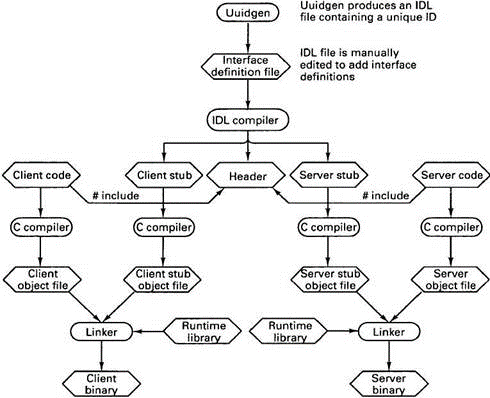
Fig 2.1(h)the steps in writing a client and a server in DCE RPC.
The first step in writing a client/server application is typically calling the uuidgen program, asking it to return up with a prototype IDL file containing an interface identifier which supplies the confirmation that never to be used again in any interface generated anywhere by uuidgen.
Uniqueness is ensured by encoding in it the actual location and time of creation. It consists of a 128-bit binary number represented within the IDL file as an ASCII string in hexadecimal. The following step is editing the IDL file, filling in the names of the remote procedures and their parameters.
It is worth noting that RPC isn’t totally transparent-for example, the client and server cannot share global variables-but the IDL rules make it impossible to represents constructs that don’t be supported. When the IDL file is complete, the IDL compiler is named to process it. The output of the IDL compiler contains three types of files:
1. A header file.
2. The client stub.
3. The server stub.
The header file consist of unique identifier, type definitions, constant definitions, and function prototypes. It should be included (using #include) in both the client and server code. The client stub contains the particular procedures that the client program will call.
These procedures are responsible for collecting and packing the parameters into the outgoing message. After that it calls the runtime system to send it. The client stub perform unpacking the reply and returning values to the client.
After that the next step is for the application writer is to write the client and server code. Both client and server are then compiled, as are the two stub procedures. The After compilation the resulting client code and client stub object files are then linked with the runtime library to provide the executable binary for the client.
Binding a Client to a Server
To allow a client to call a server, it is necessary that the server be registered and ready to simply accept incoming calls. Registration of a server makes it possible for a client to locate the server and bind to that. Server location is completed in two steps:
1. Locate the server's machine.
2. Locate the server on that machine.
To communicate with a server, the client wants to know an end point, on the server's machine therefor it can send messages. An end point is used by the server's operating system to distinguish incoming messages for different processes.
In DCE, a table which contains a(server, end point)pairs is maintained on each server machine by a process this is called as DCE daemon. Before it becomes available for incoming requests, the server needs to ask the operating system for an end point. After that it registers this end point to the DCE daemon. The DCE daemon records this information in to protocols in the end point table for future use.
The server also registers with the directory service by providing it the network address of the server's machine and a name under which the server can be looked up. Binding a client to a server then proceeds as shown in Fig.
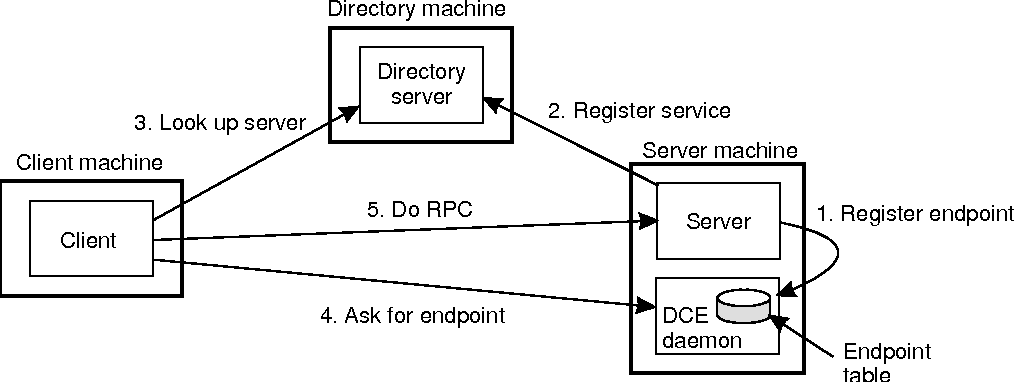
Fig 2.1(i)Client-to-server binding in DCE.
Consider the example that client wants to bind to a video server that is locally present under the name /local/multimedia/video/movies. It passes this name to the directory server and server returns the network address of the machine running the video server.
The client then goes to the DCE daemon on that machine which has a well-known end point, and asks it to look up the end point of the video server in its end point table.
Performing an RPC
The actual RPC is dispensed transparently and within the usual way. The client stub marshals the parameters to the runtime library for transmission using the protocol chosen at binding time.
When a message arrives at the server side, it’s routed to the proper server supported the end point contained within the incoming message. The runtime library passes the message to the server stub, which un-marshals the parameters and calls the server. The reply goes back by the reverse route.
Remote procedure calls and remote object invocations contribute to hiding communication in distributed systems there for they enhance access transparency.
Message-Oriented Transient Communication
Many distributed systems and applications are built directly on top of the straight forward message-oriented model provided by the transport layer.
Berkeley Sockets
The interface of the transport layer to give permission to programmers to make use of its entire suite of (messaging) protocols through a set of primitives.
As an example the sockets interface as introduced within the 1970s in Berkeley UNIX. A socket could be a communication end point to which an application can write data that are to be sent out over the underlying network, and from which incoming data may be read.
A socket forms an abstraction over the particular communication end point that is used by the local operating system for a specific transport protocol. In the following text, we consider the socket primitives for TCP, which are shown in Fig. 2.2(a).
Primitive | Meaning
|
Socket | Create a new communication end point |
Bind | Attach a local address to a socket |
Listen | Announce willingness to simply accept connection |
Accept | Block caller until connection request arrives |
Connect | Actively try to establish connection |
Send | Send some data over connection |
Receive | Receive some data over connection |
Close | Release the connection |
Fig 2.2(a) the socket primitives for TCP/IP.
Servers generally execute the primary four primitives, normally in the given order. When system call the socket primitive, the caller creates a new communication end point for respective transport protocol. The bind primitive assigns a local address with the newly-created socket.
The listen primitive is called only within the case of connection-oriented communication. It is a non-blocking call that permits the local operating system to reserve required buffers for a specified maximum number of connections that the caller is ready to simply accept.
A call to just accept blocks the caller until a connection request arrives. When a call for request arrives, the local operating system creates a new socket with the identical properties same as the original one, and returns it to the caller.
This approach will allow the server to, as an example, fork off a process that may subsequently handle the particular communication through the new connection. The server, within the meantime, can return back and wait for another connection request on the original socket.
The Message-Passing Interface (MPI)
In message oriented primitive Sockets were treated as insufficient for two reasons first is wrong level of abstraction by supporting simple send, receive primitive and second is sockets are designed using general purpose stack like TCP/IP.

Fig 2.2(b).Connection-oriented communication pattern using sockets.
The need to be hardware and platform independent eventually led to the definition of a standard for message passing, which is called as the Message-Passing Interface or MPI.
MPI is developed for parallel applications and as such is ready-made to transient communication. It makes direct use of the underlying network. Also, it assumes that serious failures like process crashes or network partitions are fatal and don’t require automatic recovery.
MPI consider communication takes place within a known group of processes. Each group is assigned an identifier. Each process within a group is assigned a (local) identifier. A (group/D, process/D) pair therefore uniquely identifies the source or destination of a message, and is used rather than of a transport-level address.
There is also several, possibly overlapping groups of processes involved in a computation which are all executing at the same time. At the core of MPI are messaging primitives to support transient communication, of which are summarized in Fig. 2.10.
Primitive | Meaning
|
MPI_bsend | Append outgoing messages to a local send buffer |
MPI_send | Send a message and wait until copied to local or remote buffer |
MPI_ssend | Send a message and wait until receipt is start |
MPI_sendrecv | Send a message and wait for reply |
MPI_isend | Pass reference to outgoing message, and continue |
MPI_issend | Pass reference to outgoing message, and wait until receipt is start |
MPI_recv | Receive a message ,block if there is none |
MPI_irecv | Check if there is incoming message , but don’t block |
Fig 2.2(c ) shows the different message-passing primitives of MPI.
In a centralized system, time is unambiguous. When a process wants to understand the time, it makes a system call and the kernel tells it. If process A asks for the time. And then a little later process B asks for the time, the value that B gets will be higher than or equal to the value A got. It will certainly not be lower.
In a distributed system, achieving agreement on time is not difficult task. Normally, in UNIX operating system, large programs are divide into multiple source files, so that a change to one source file only requires one file to be recompiled, not all the files. If a program consists of 100 number of files, in that they not recompile everything because one file has been changed greatly increases the speed at which programmers can work.
Following figure shows the clock synchronization.
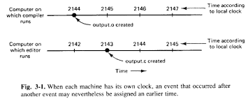
Fig 2.3(a)shows every computer has its own clock, an incident is occurred after another event may nevertheless be assigned an earlier time.
- Physical clock
The physical clocks are used to adjust the time of every node. Each node within the system can share its standard local time with other nodes in the system. The time is set depends on UTC (Universal Time Coordination). UTC is consider as a reference time clock for the nodes in the system.
Several earth satellites also offer a UTC service. The Geostationary Environment Operational Satellite provides UTC accurately to 0.5 m sec, and also other satellites provide the better UTC.
Using shortwave radio or satellite services requires an accurate knowledge of the relative position of the sender and receiver, in order to compensate for the signal propagation delay.
The clock synchronization can be implemented by using two ways that is External and Internal Clock Synchronization.
1.External clock synchronization is the one in which an external reference clock is present. It is used as a reference time and the nodes in the system can set and adjust their time accordingly.
2.Internal clock synchronization is the one in which each node shares its time with other nodes and all the nodes set and adjust their times accordingly.
There are two types of clock synchronization algorithms consider as Centralized and Distributed.
- Centralized is the one in which a time server is used as a reference. The single time server distributes it’s time to the nodes and all the nodes adjust the time accordingly. It is dependent on single time server if this single time server node fails, the whole system will lose synchronization. Examples of centralized are- Berkeley Algorithm, Passive Time Server, Active Time Server etc.
b. Distributed is the one in which there is no centralized time server present. Instead the nodes adjust their time by using their local time and then, taking the average of the differences of time with other nodes. Distributed algorithms overcome the issue of centralized algorithms like the scalability and single point failure. Consider the xamples of Distributed algorithms is Global Averaging Algorithm, Localized Averaging Algorithm and NTP that is Network time protocol.
Clock Synchronization algorithms
Each computer consist of a clock which is an electronic device that counts the oscillations in a crystal at a particular frequency. Synchronization of these physical clocks to some known high degree of accuracy is needed. This helps to measure the time relative to each local clock to determine order between events.
Physical clock synchronization algorithms can be classified as centralized and distributed.
1.Centralized clock synchronization algorithms
The centralized clock synchronization algorithm have one node with a real-time receiver and are called time server node. The clock time of this node is provided as correct and used as reference time.
The goal of this algorithm is to maintain the clocks of all other nodes synchronized with time server node.
- Cristian’s Algorithm
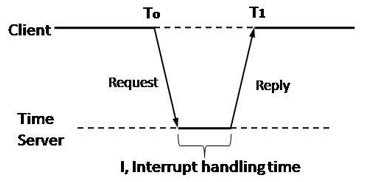
Fig 2.3(b) Cristian’s Method.
In this method each node periodically sends a message to the server. When the time server receives the message it responds with a message T, where T is the current time of server node.
Assume the clock time of client be T0 when it sends the message and T1 when it receives the message from server. T0 and T1 are measured using same clock so best estimated time for propagation is (T1-To)/2.
When the reply is received at client’s node, its clock is readjusted to T+(T1-T0)/2. There can be unpredictable variation in the message propagation time between the nodes hence (T1-T0)/2 is not good to be added to T for calculating current time.
For this several measurements of T1-To are made and if these measurements exceed some threshold value then they are unreliable and discarded. The average of the remaining measurements is calculated and therefore the minimum value is taken under consideration accurate and half of the calculated value is added to T.
Advantage-It assumes that no additional information is available.
Disadvantage- It restricts the quantity of measurements for estimating the value.
B. The Berkley Algorithm
This is an active time server approach where the time server periodically broadcasts its clock time and therefore the other nodes receive the message to correct their own clocks.
In this algorithm the time server periodically sends a message to all or any the computers in the group of computers. When this message is received by computer then each computer sends back its own clock value to the time server. The time server has a prior knowledge of the approximate time required for propagation of a message which is used to readjust the clock values. It then accept a fault tolerant average of clock values of all the computers. The calculated average is consider becausethe present time to which all clocks should be readjusted.
The time server readjusts its own clock to this value and rather than sending the current time to other computers it sends the amount of time each computer needs for readjustment. This will be positive or negative value and is calculated supported on the knowledge the time server has about the propagation of message.
2. Distributed algorithms
Distributed algorithms reduce the issuees of centralized by internally synchronizing for better accuracy. One of the two approaches can be used:
A.Global Averaging Distributed Algorithms
In this algorithm the clock process at each node broadcasts or sends its local clock time in the form of a “resync” message at the beginning of every fixed-length resynchronization interval. This is done when its local time equals To+iR for some integer i, where To is a fixed time agreed by all nodes and R is a system parameter that depends on total nodes in a system.
After broadcasting the clock value, the clock process of a node waits for time T which is determined by the algorithm.
During this waiting the clock process collects the resync messages and the clock process records the time when the message is received which estimates the skew after the waiting is done. It then computes a fault-tolerant average of the estimated skew and uses it to correct the clocks.
B.Localized Averaging Distributes Algorithms
The global averaging algorithms do not scale as they need a network to support broadcast facility and a lot of message traffic is generated.
Localized averaging algorithms overcome these drawbacks as the nodes in distributed systems are logically arranged in a pattern or ring.
Each node exchanges its clock time with its neighbors and then sets its clock time to the average of its own clock time and of its neighbors.
C.Network Time Protocol
NTP is an Internet protocol that serves to synchronize the clocks of computers. It uses UTC that is Coordinated Universal Time as time reference. NTP is developed by David. Mills. NTP is a fault tolerant protocol which automatically select the best source from several available time sources to synchronize.
Working of NTP
The distributed system may consist of multiple reference clocks. Each node the network can exchange information may be bidirectional or unidirectional. A client node can send request message to its directly connected time server node or nearly connected node so the propagation time from one node to another node forms hierarchical graph with reference clocks at the top. This hierarchical structure is known as strata synchronization subnet where each level is referred as strata.
NTP servers synchronize with each other in one of the three modes:
- Multicast Mode:
In this type of synchronization, one or more than one servers sequentially multicast their time to the other servers running in the network. Other servers set their time during the transaction accordingly by adding a small delay. This method is proposed for use in a high-speed Local Area Network (LAN).
Ii. Procedural Call Mode:
It is same as the process of Cristian’s algorithm. During this procedural call mode one server accepts requests from other computers and server replies with its current clock time. It gives more accurate time than multicast mode. It may be used where multicast is not supported in hardware.
Iii. Symmetric Mode:
During this mode of synchronization the pair of server exchanges messages. Servers supply time information in LANs and higher levels of the synchronization subnet where the best accuracy is to be achieved.
There are some drawbacks of NTP protocol as follows:
a)NTP supports UNIX operating systems only.
b)For windows there are problems with time resolution, reference clock drives, authentication and name resolution.
A logical clock could be a mechanism for capturing chronological and causal relationships in an exceedingly distributed system.
Unlike physical clocks which are physical entities that assign physical times to events, our clocks are simply a conceptualization of function that assigns numbers to events. These numbers act as timestamps which help us to order the different events. Since our clocks logically order events, rather than physically organize them, we call them logical clocks.
Lamport's Algorithm for Logical Clocks
To synchronize logical clocks, Lamport defines a relation is called as happens-before relation. The expression a ~ b is read "a happens before b" and means all processes agree that first event a occurs, then afterward, event b occurs. The happens-before relation is observed directly in two situations:
1. If a and b are events within the same process, and a occurs before b, thena ~ b is true.
2. If a is that the event of a message being sent by one process, and b is that theevent of the message being received by another process, then a ~ bis additionally true. A message can’t be received before it’s sent, or even at the same time it is sent, since it takes a finite, nonzero amount of your time to arrive.
Happens-before could be a transitive relation, so if a ~ band b ~ c, then a ~ c. If two events, x and y, happen in several processes that do not exchange messages (not even indirectly via third parties), then x ~ y is not true, but neither is y ~ x.
These events are said to be concurrent, which simply means that nothing can be said about when the events happened or which event happened first.
Following is the example of logical clocks.
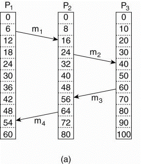
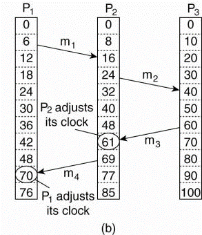
Fig.2.4(a) Three processes, each with its own clock. The clocks run at different rates.(b) Lamport's algorithm corrects the clocks.
- The processes run on different machines, each with its own clock, running at its own speed.
- When the clock has ticked 6 times in process P1, it’s ticked 8 times in process P2 and 10 times in process P3.
- Each clock runs at a constant rate, but the rates are different because of differences within the crystals.
- At time 6, process P1 sends message from m1 to process P2, when it arrives in system the clock in process P2 reads 16.
- If the message carries the starting time, 6, in it, process P2 will conclude that it took 10 ticks to create the journey.
- m3 leaves process P3 at 60 and arrives at P2 at 56.
- m4 from P2 to P1 leaves at 64 and arrives at 54.
- These values are clearly impossible. It is this situation that must be prevented.
- Since m3 left at 60, it must arrive at 61 or later.
- Each message carries the sending time according to the sender's clock.
- When a message arrives and also the receiver's clock shows a value prior to the time the message was sent, the receiver fast forwards its clock to be one more than the sending time.
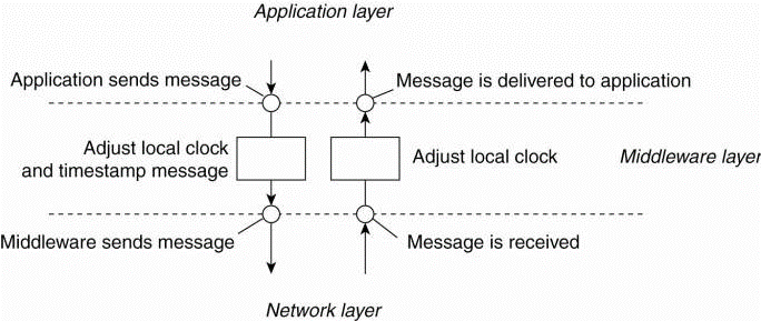
Fig 2.4(c )the positioning of Lamport's logical clocks in distributed systems.
Example: Totally Ordered Multicasting
As an application of Lamport's logical clocks, consider the true within which a database has been replicated across several sites. For example,a bank may place copies of an account database in two different cities to boots query performance, say New York and San Francisco.
A query is often forwarded to the nearest copy. The price for a quick response to a query is partly paid in higher update costs, because each update operation must be performed at each replica.
Following figure shows the updating a replicated database and leaving it in an inconsistent state.
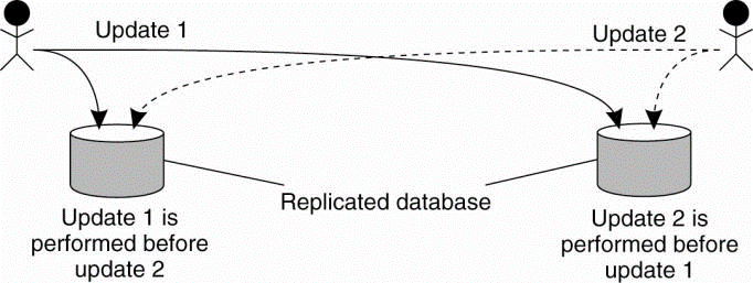
Fig 2.4(d)Updating a replicated database and leaving it in an inconsistent state.
Fundamental to distributed systems is that the concurrency and collaborationamong multiple processes. This suggests that processes will haveto simultaneously access the identical resources.
To prevent concurrent accesses of that corrupt the resources and make it inconsistent, by using grant mutual exclusive access by processes.
Overview
Distributed mutual exclusion algorithms will be classified into two different categories.
1. Token-based solutions
In this mutual exclusion is achieved by passing a special message between the processes, referred to as a token. There’s only one token available and whoever has that token is allowed to access the shared resource. When finished sharing resources the token is passed on to a next process.
Token-based solutions have some important properties. First, depending on the how the processes are organized, they can fairly easily make sure that every process will get an opportunity at accessing the resource.
Second, deadlocks by which several processes are waiting for one another to proceed, can easily be avoided, contributing to their simplicity.
The main drawback of token-based solutions could be a rather serious one: when the token is lost, an intricate distributed procedure has to be started to make sure that a new token is created, but in particular, that it is also the only token.
2.Permission-based approach
In permission- based approach a process wanting to access the resource for this it requires the permission of other processes. There are many various ways toward granting such a permission.
A Centralized Algorithm
The way to achieve mutual exclusion in a distributed system is to simulate how it is done in a one-processor system. One process is elected because the coordinator.
When a process wants to access a shared resource then it sends a request message to the coordinator stating which resource it wants to access and requesting for permission. If no other process is currently accessing that resource, the coordinator sends back a reply granting permission, as shown in Fig (a).
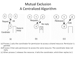
Fig (a) shows Process 1 asks the coordinator to give permission to access a shared resource and permission is granted. (b) Then process 2 asks permission to access the same resource. The coordinator does not send any reply. (c) When process 1 releases the resource, it tells the coordinator, then it replies to process 2.
Consider another process, 2 in Fig. (b), asks for permission to access the resource. The coordinator knows that a different process is already at the resource, so it cannot grant permission.
The appropriate method used to deny permission is system dependent. Fig. (b) show the coordinator which refrains from replying, for blocking process 2, which is waiting for a reply. Alternatively, it could send a reply saying "permission denied." Either way, it queues the request from 2 for the time being and waits for more messages.
When process 1 is finished with the resource, it sends a message to the coordinatorreleasing its exclusive access, as shown in Fig.6-14(c). The coordinator which takes the first item off the queue of deferred requests and sends that process a grant message. If the method was still blocked (i.e., this is the first message to it), it unblocks and accesses the resource.
A Decentralized Algorithm
Taking a single coordinator is often a poor approach. Let us take a look at fully decentralized solution. Lin et al. (2004) derive to use a voting algorithm that can be executed using a DHT-based system. In requirement of their solution extends the central coordinator in the following way. Each resource is assumed to be replicated n times. Every replica has its own coordinator for controlling the access by concurrent processes.
This scheme essentially makes the original centralized solution less vulnerable to failures of a single coordinator. The assumption is that when a coordinator crashes, it recovers quickly but will have forgotten any vote it gave before it crashed. Another way of viewing coordinator is that a coordinator resets itself at arbitrary moments.
A Distributed Algorithm
Only having a probabilistically correct algorithm is just not sufficient. That’s why researchers find out deterministic distributed mutual exclusion algorithms. The first paper on clock synchronization is published byLamport's in 1978. Ricart and Agrawala (1981) made it more useful to this.
The algorithm works as follows. When a process wants to access a shared resource, it builds a message containing the name of the resource, its process number, and the current (logical) time. It then sends the message to all other processes, conceptually including itself. The sending of messages is assumed to be reliable; that is, no message is lost.
When a process receives a request message from another process, the action it takes depends on its own state with respect to the resource named in the message.
Three different cases have to be clearly distinguished:
1. If the receiver is not accessing the resource and does not want to access it, it sends back an OK message to the sender.
2. If the receiver already has access to the resource, it simply does not reply. Instead, it queues the request.
3. If the receiver wants to access the resource as well but has not yet done so, it compares the timestamp of the incoming message with me and the contained in the message that it has sent everyone. The lowest one wins. If the incoming message has a lower timestamp then the receiver sends back an OK message to client. If its own message has a lower timestamp then the receiver queues the incoming request and sends nothing.
After sending out requests asking permission, a process sits back and waits until everyone else has given permission. As soon as all the permissions are in, it may go ahead. When it is finished, it sends OK messages to all processes on its queue and deletes them all from the queue. If there is no conflict, itclearly works. However, suppose that two processes try to simultaneously access the resource, as shown in Fig. (a).
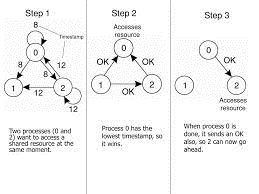
Fig (a) shows when two processes want to access a shared resource at the sametime. (b) Process 0 has the lowest timestamp that’s why it wins. (c) When process 0 is done, it sends an OK message also, so 2 can now go ahead.
In this Process 0 sends a request to everyone with timestamp 8, while at the same time, process 2 sends a request to everyone with timestamp 12. If Process 1 is not interested to access the resource then it sends OK to both senders. Processes 0 and 2 both processes see the conflict and compare timestamps.
Process 2 sees that it has lost then it grants permission to 0 by sending OK. Process 0 now queues the request from 2 for later processing and access the resource, as shown in Fig. (b). After finishing, it removes the request 2 from its queue and sends an OK message to process 2 that give permission to latter to go ahead, as shown in Fig.(c).
A Token Ring Algorithm
A Token Ring is completely different approach provided to achieve mutual exclusion in a distributed system which is shown in following Fig. Here we have a bus network for e.g. Ethernet, with no particular ordering of the processes.
In software, a logical ring is constructed in which each process is assigned a position in the ring shown in Fig.(b). The ring positions may be allocated in numerical order of network addresses. It does not matter what the ordering is matters is that each process knows who is next in line after itself.
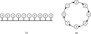
Fig (a) An unordered group of processes on a network. (b) A logicalring constructed in software.
When the ring is initialized the process 0 is given a token then the token circulates around the ring. It is passed from process k to process k +1 in point-to-point messages. When a process acquires the token from its neighbor first it checks to see if it needs to access the shared resource.
If so, the process goes ahead and perform all the task which is required and releases the resources. After it has finished, it passes the token along the ring. It is not given access to immediately enter the resource again using the same token.
If a process is transfer the token by its neighbor and is not interested in the resource, it just passes the token along. In condition when no processes need the resource, the token just circulates at high speed around the ring.
The correctness of this algorithm is easy. Only one process has the token at any instant, so only one process can actually get to the resource. Since the token circulates among the processes in a well-defined order then starvation cannot occur process. Once a process decides it wants to have access to the resource, at any case it will have to wait for every other process to use the resource.
Distributed algorithms require one process to act as a coordinator or initiator. To decide which process becomes the coordinator the Election algorithms is used.
Election algorithms are created for electing a coordinator process from among the currently running processes in such a manner that at any instance of time there is a single coordinator for all processes in the system.
The goal of an election algorithm is to confirm that when an election starts it concludes with all the processes agreeing on who the coordinator should be.
Therefore an election algorithm basically finds out which of the currently active processes has the highest priority number and then informs this to all other active processes.
- Bully Algorithm
This algorithm was proposed by Garcia-Molina.
When the process notices that the coordinator are not long time responding to requests, it initiates an election. A process P holds an election as follows:
- P sends an ELECTION message to all processes which are with higher numbers.
- If no one responds then P wins the election and becomes the coordinator.
- If one of the higher-ups answers, it takes over. P’s job is done.
- A process can get an ELECTION message at any time from one amongst its lower numbered neighbor process.
- When such a message arrives, the receiver sends an OK message back to the sender to point that he is alive and will take over. The receiver then holds an election, unless it’s already holding one.
- All processes quite except one that’s the new coordinator. It announces its victory by sending all processes a message telling them that starting immediately it’s the new coordinator.
- If a process that was previously down comes back up, it holds an election. If it happens to the highest numbered process which is currently running then it will win the election and get the coordinator’s job. Thus the most important guy in town always wins, hence the name “bully algorithm”.
- Example:
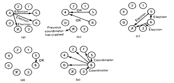
In fig(a) a group of eight processes taken is numbered from 0 to 7. Assume that previously process 7 was the coordinator, but it has just crashed because of some reason. Process 4 notices if first and sends ELECTION messages to all the processes higher than it that is 5, 6 and 7.
In fig (b) processes 5 and 6 both respond with OK. Upon getting the primary of these responses, process4 job is completed. It knows that one of these will become
The coordinator. It just sits back and waits for the winner.
In fig(c), both 5 and 6 hold elections by each sending messages to those processes higher than itself.
In fig(d), process 6 tells 5 that it will take over with an OK message. At this point 6knows that 7 is dead and that (6) it is the winner. It there is state information to be collected from disk or pick up where the old coordinator left off, 6 must now do what is required.
When it is ready to take over, 6 announce this by sending a COORDINATOR message to all running processes. When 4 gets this message, it can now continue with the operation it had been trying to do when it discovered that 7 was dead, but using 6 as the coordinator this time. In this way the failure of is handled and therefore the work can continue.
If process 7 is again restarted then it will just send all the others a COORDINATOR message and forward them into submission.
Ii. Ring Algorithm
This algorithm uses a ring for its election but doesn’t use any token. During this algorithm it’s assumed that the processes are physically or logically ordered so that each processor already knows its successor.
When any process notices that a coordinator isn’t functioning, it builds an ELECTION message containing its own process number and sends the message to its successor. If the successor is down the sender skips the successor and goes to the next member together with the ring until a process is located.
At each step the sender adds its own process number to the list within the message making itself a candidate to elected as coordinator
The message gets back to the process that started it and recognizes this event because the message consists its own process number.
At that point the message type is modified to COORDINATOR and circulated yet again to tell everyone who the coordinator is and who are the new members. The coordinator is chosen with the process having highest number.When this message is circulated once it’s removed and normal work is preceded.
Reference Book
- Distributed Systems: Principles and Paradigms- Tanenbaum, Steen.