Unit 3
Distributed File System and fault Tolerance
Distributed file system known as DFS provide method for storing and accessing files based in a client/server architecture. In a distributed file system, one or more central servers store files that can be accessed by any number of remote clients in the network with appropriate authorization rights.
Distributed file system organize files in hierarchical file management system which is same as operating system. This system uses a uniform naming convention and a mapping scheme to keep track of in which location files are located.
Two main reason of using files:
1. for permanent storage of information on a secondary storage media.
2. To Sharing of information between applications.
A file system is a subsystem of the operating system which performs file management activities such as organization of files, storing, and retrieval of information, naming, sharing, and protection of files. A file system frees the programmer from managing the details of space allocation and layout of the secondary storage device.
The design and implementation of a distributed file system is more complex than a conventional file system because of the fact that the users and storage devices are physically spread over the wide area.
Following are the functions of distributed file system:
1. Remote information sharing
In this any node from any physical location of the file, can access the file.
2. Usermobility
User should have the permission for working on different nodes.
3. Availability
For better fault-tolerance, files should be available for use even if the failure is occurs. Therefore the system should maintain multiple copies of the files and existence of the file is to be transparent to the user.
4. Diskless workstations
A distributed file system, with use of transparent remote-file accessing ability it allows the use of diskless workstations in a system.
A distributed file system provides the following types of services:
- Storage service
It contains Allocation and management of space on a secondary storage device and also provide a logical view of the storage system.
2. True file service
It contains file-sharing semantics, file-caching mechanism, file replication mechanism, concurrency control, multiple copy update protocol etc.
3. Name/Directory service
Distributed file system is manages directory related activities such as creation and deletion of directories, adding a new file to a directory, deleting a file from a directory, changing the name of a file, moving a file from one directory to another etc.
A distributed system is an intermediate level of system administrators. The administrators manage the common storage, shared permanent storage and its security. Consider the example of distributed file system such as OSF’s DFS or any future location-independent object management system.
1) Client-Server Architectures
The client-server architectures is the collection of multiple distributed file system. Network File System (NFS) is one of the most widely-deployed UNIX-based systems.
The basic idea of NFS is that each file server provides a standardized view of its local file system. In Network File System it should not matter how that local file system is implemented but each NFS server supports the same model. This method has been used for other distributed files systems also. NFS provides a communication protocol that allows clients to access the files stored on a server and allow a heterogeneous collection of processes, which are running on different operating systems and machines, to share a common file system.
In this model, clients are provide transparent access to a file system that is managed by a remote server. Therefore clients are normally unknown of the actual location of files. Instead of they offered an interface to a file system which is same as the interface offered by a conventional local file system.
The client is offered only an interface containing various file operations, but the server is only responsible for implementing those operations. This model is also referred as the remote access model. Following figure shows the model.
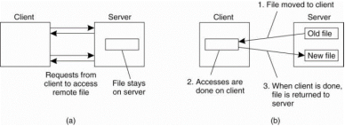
Figure 3.1(I) (a) the remote access model. (b) The upload/download model.
As compare with client server model in the upload/download model a client accesses a file locally after having downloaded it from the server. When the client is finished with the file, it is uploaded back to the server again therefore it can be used by another client.
The Internet's FTP service is also used in this way when a client downloads a complete file, modifies it, and then puts it back.NFS has been implemented for a huge number of different operating systems. All modern UNIX systems, NFS is implemented in following the layered architecture shown in Fig.
Virtually all modem operating systems provide VFS. With NFS, operations on the VFS interface are either passed to a local file system, or passed to a separate component known as the NFS client. This client takes care of handling access to files stored at a remote server.
In NFS all client-server communication is carried out through RPCs. The NFS client implements the NFS file system operations same as RPCs to the server. The operations offered by the VFS interface can be different from those offered by the NFS client. The idea of the VFS is to hide the differences between various file systems.
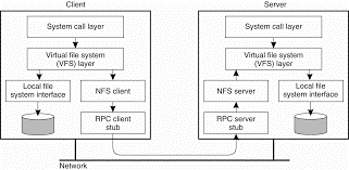
Figure 3.1(II)the basic NFS architecture for UNIX systems.
2) File System Model
The file system model offered by NFS is the same as the offered by UNIX-based systems. Files are consider as un-interpreted sequences of bytes. They are organized into a naming graph in which nodes represent directories and files.
NFS supports hard links and symbolic links same as inany UNIX file system. Files are named but accessed by same as of a UNIX-like file handle. In other way, to access a file, a client must first look up its name in a naming service and obtain the associated file handle. Therefore each file has a number of attributes whose value scan be looked up and changed.
Following figure shows the general file operations supported by NFS versions 3 and4, respectively. The create operation is used to create a file, but has different meanings in NFSv3 and NFSv4. In version 3, the operation is used for creating regular files and special files are created using separate operations. The link operation is used to create hard links, Symlink is used to create symbolic links and Mkdiris used to create subdirectories. Special files, such as device files, sockets and named pipes are created by mknod operation.
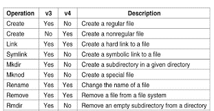
Figure 3.1(III)shows list of file system operations supported by NFS.
3) Cluster-based architectures
A cluster-based architecture overcome some issues in client-server architectures and improve the execution of applications in parallel. The file-striping technique is used in which a file is split into multiple chunks, which are "striped" across several storage servers.
The goal of this architecture is to allow access to different parts of a file in parallel. If the application does not get advantage from this technique, then it would be convenient to store different files on different servers.
When we want to organizing a distributed file system for large data centers, such as Amazon and Google, that offer services to web clients allowing multiple operations such as reading, updating, deleting to a large number of files distributed among a large number of computers, then cluster-based solutions become more efficient.

Figure 3.1(IV) shows difference between (a) distributing whole files across severalServers and (b) striping files for parallel access.
Two of the most widely used distributed file systems (DFS) are Google File System (GFS) and the Hadoop Distributed File System (HDFS).
Design principles
Goals
Google File System and Hadoop Distributed File System are built for handling batch processing on very large data sets. Consider the following features
- High availability in this the cluster contain thousands of file servers and some of them can be off at any time.
- A server is from a rack, a room, a data center, a country, and a continent, in order to correctly identify its geographical location.
- The size of a file can be change in from many gigabytes to many terabytes. The file system should be able to support a more number of files.
- The need to support append operations on a file and allow file contents to be visible even if a file is being written.
- Communication is reliable among working machines for that TCP/IP is used with a remote procedure call RPC.
- TCP allows the client to know when there is a problem and a need to make a new connection.
Load balancing
Load balancing is required for efficient operation in distributed system. It means divide the work among different servers in order to get more work done in the same amount of time and to process clients faster. In a system containing N chunks servers in a cloud N is 1000, 10000, or more where a certain number of files are stored, each file is split into multiple parts or chunks of fixed size.
The load of each chunks server is proportional to the number of chunks hosted by the server. In a load-balanced cloud the resources can be efficiently used while maximizing the performance of MapReduce-based applications.
Load rebalancing
In a cloud computing environment due to the failure chunk servers may be upgraded, replaced, and added to the system. Files are also be dynamically created, deleted, and appended. Because of this load imbalance is comes in distributed file system that means the file chunks are not distributed equitably between the servers.
Distributed file systems in clouds such as GFS and HDFS rely on central or master servers or nodes to manage the metadata and the load balancing. The master rebalances replicas at particular time in that data must be moved from one DataNode/chunkserver to another if there is free space on the first server falls below a certain threshold.
Therefore if this centralized approach is a bottleneck for those master servers, if they become unable to manage a large number of file accesses, as it increases their already heavy loads. The load rebalance problem is NP-hard.
When we want large number of chunk servers to work in collaboration, and to solve the problem of load balancing in distributed file systems, several techniques have been proposed, such as reallocating file chunks. In that the chunks can be distributed as uniformly as possible while reducing the movement cost as much as possible.
A.Google File System
Google the biggest worldwide internet company created its own distributed file system, named Google File System (GFS). Purpose is to meet the rapidly growing demands of Google's data processing needs, and it is used for all cloud services. It is also a scalable distributed file system for data-intensive applications. It provides feature like fault-tolerant, high-performance data storage a large number of clients accessing it simultaneously.
It uses MapReduce algorithm which allows users to create programs and run them on multiple machines without thinking about parallelization and load-balancing issues. GFS architecture is based on having a single master server for multiple chunk servers and multiple clients.
The master server running in selected node is responsible for coordinating storage resources and managing files metadata. In this every file is divide into multiple chunks of 64 megabytes. Each chunk is stored in a chunk server. A chunk is identified by a chunk handle through a globally unique 64-bit number that is assigned by the master when the chunk is first created.
The master server maintains all of the files metadata consist of file names, directories, and the mapping of files to the list of chunks that contain each file's data. The metadata is kept in the master server's main memory with the mapping of files to chunks. Updates to this data is logged in operation log on disk. This operation log is replicated onto the remote machines. When the log become too large then checkpoint is made and the main-memory data is stored in a B-tree structure to maintain mapping back into main memory.
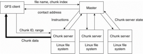
Figure 3.1(V)the organization of a Google cluster of servers.
Fault Tolerance
To perform fault tolerance, each chunk is replicated onto multiple chunk servers by default there is 3 chunks. A chunk is available on at least one chunk server this is maintained for simplicity. The master is responsible for allocating the chunk servers for each chunk and is contacted only for metadata information. For other data, the client needs to be interact with the chunk servers.
The master keeps track of where a chunk is located therefore it only occasionally contacts the chunk servers to see which chunks they have stored. This allows for scalability and helps prevent bottlenecks due to increased workload.
In GFS many files are modified by appending new data and not overwriting existing data.
File Processing
When a client wants to write or update a file, the master will assign a replica, which will be the primary replica if it is the first modification. The process of writing is divide into two steps:
- Sending: This is a most important first step in which the client contacts the master to find out which chunk servers hold the data. The client is given a list of replicas to identify the primary and secondary chunk servers. The client then contacts the nearest replica chunk server, and sends the data to it. This server will send the data to the next closest one, which then forwards it to another replica this process continues. The data is then only propagated and cached in memory but not written to a file.
- Writing: After all the replicas have received the data, the client sends a write request to the primary chunk server to identifying the data that was sent in the sending phase. Then the primary server assign a sequence number to the write operations that it has received, apply the writes to the file in serial-number order, and forward the write requests in that order to the secondary files. In middle, the master is kept out of the loop.
There are two types of flows the data flow and the control flow. Data flow is related with the sending phase and control flow is related with the writing phase. This assures that the primary chunk server takes control of the write order. When the master assigns the write operation to a replica, it increments the chunk version number and informs all of the replicas containing that chunk of the new version number. Chunk version numbers allow for update error-detection, if a replica wasn't updated because its chunk server was down.
Some new Google applications did not work with the 64-megabyte chunk size. This problem is solved by implementing the Bigtable approach.
Symmetric Architectures
Symmetric organizations are based on peer-to-peer technology. All current system use a DHT-based system for distributing data, combined with a key-based lookup mechanism.
Consider example of the first type of file system is Ivy, a distributed file system that is built using a Chord DHT-based system. Ivy system consists of three separate layers as shown inFig. The lowest layer is created by a Chord system providing basic decentralized lookup facilities. The middle layer is a fully distributed block-oriented storage layer. Top layer is implementing an NFS-like file system.
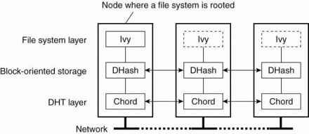
Fig 3.1(VI) the organization of the Ivy distributed file system.
Data storage in Ivy is formed by a Chord-based, block-oriented distributed storage system called DHash (Dabek et al., 2001). It knows about data blocks, each block is of a size of 8KB. Ivy uses two types of data blocks. A content-hash block has an associated key, which is consider as the secure hash of the block's content. In this way, when a block is looked up, a client can immediately verify whether the correct block has been looked up, or not or corrupted version is returned.
Ivy also makes use of public-key blocks that having a public key as lookup key, and content has been signed with the associated private key. To increase availability, DHash replicates every block B to the k immediate successors of the server responsible for storing B. The looked up blocks are also cached along with the lookup request followed.
Files are implemented as a separate data structure on top of DHash. To achieve this goal, each user maintains a log of operations it carries out on files. Consider that there is only a single user per node so that each node will have its own log. A log is a linked list of immutable records in that every record contains all the information related to an operation on the Ivy file system.
Each node joins records only to its own, local, log. Only a log head is mutable,and points to the recently appended record. Each record is stored in a separate content-hash block and a log's head is kept in a public-key block.
There are different types of cooperating processes such as storage servers and file managers. The important aspect concerning file system processes is whether or not they should be stateless. NFS is a best example describing the trade-offs. One of its features is the servers were stateless. The NFS protocol did not require that servers maintained any client state. This approach was followed in versions 2 and 3, but not in for version 4.
The main advantage of the stateless approach is simplicity. For example, when a stateless server crashes, there is no need to enter a recovery phase to bring the server to a previous state. However, we still need to take into account that the client cannot be given any guarantees whether or not a request has actually been carried out.
The stateless approach in the NFS protocol not always be implement in practically. For example locking a file cannot easily done by a stateless server. In the case of NFS, a separate lock manager is required to handle this situation. Same as certain authentication protocols require that the server maintains state on its clients. NFS servers designed in such a way that only very little information on clients needed to be maintained.
Comparing with the version 4 the new protocol is designed in such a way that a server does not need to maintain much information about its clients. An important reason for choosing the stateless protocol is that NFS version4 is expected to also work across wide-area networks. This provides efficient cache consistency protocol.
The important difference with the previous versions is the support for the open operation. In addition, NFS supports callback procedures by which a server can do an RPC to a client and callbacks also require a server to keep track ofits clients.
As with processes, there is nothing particularly about communication in distributed file systems. Many of them are based on remote procedure calls (RPCs). The main reason for selecting an RPC mechanism is to make the system independent from underlying operating systems, networks, and transport protocols.
RPCs in NFS
In NFS, all communication between a client and server take place along with the Open Network Computing RPC (ONC RPC) protocol, which is defined in Srinivasan (1995a), along with a standard for representing marshaled data (Srinivasan, 1995b).
Every NFS operation can be implemented as a single remote procedure call toa file server. In NFSv4 the client was made responsible for making the server's life easy by keeping requests relatively simple. For example, to read data from a file for the first time, a client first had to look up the file handle using the lookup operation, after which it could issue a read request which is shown in Fig. (a).
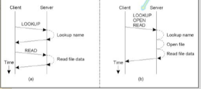
Fig shows 3.3(I)(a) Reading data from a file in NFS version 3. (b) Reading datausing a compound procedure in version 4.
In this approach there are two successive RPCs. The drawback occurs when the use of NFS in a wide-area system. In this case, the extra latency of a second RPC led to performance degradation. To overcome this problems, NFSv4 supports compound procedures by which several RPCs can be grouped into a single request, as shown in Fig. (b).
In example, the client combines the lookup and read request into a single RPC. In the case of version 4, it is also necessary to open the file before reading can take place. After the file handle is take place it is passed to the open operation, after which the server continues with the read operation. The effect in this example is that only two messages need to be exchanged between the client and server.
The RPC2 Subsystem
RPC2 is a package that provides reliable RPCs on top of the unreliable UDP protocol. Each time a remote procedure is called, the RPC2 client code starts a new thread that sends an invocation request to the server and subsequently blocks until it receives an answer.
As request processing take time to complete, the server regularly sends back messages to the client to let it know it is still working on the request. If the server dies, sooner or later this thread will notice that the messages have ceased and report back failure to the calling application.
An RPC2 is support for side effects. A side effect is a process by which the client and server can communicate using an application-specific protocol. Consider example, a client opening a file at a video server. There is need that the client and server set up a continuous data stream with an isochronous transmission mode. That means data transfer from the server to the client is guaranteed to be within a minimum and maximum end-to-end delay.
RPC2 allows the client and the server to set up a separate connection for transferring the video data to the client on time. Connection setup is performed as a side effect of an RPC call to the server. For this the RPC2 runtime system provides an interface of side-effect routines that is implemented by the application developer. For example, there are routines for setting up a connection and transferring data. These routines are automatically called by theRPC2 runtime system at the client and server, respectively. But their implementation is completely independent of RPC2. This principle of side effects is shown in following Fig.
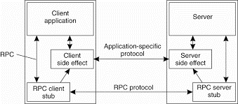
Fig 3.3(II)Side effects in Coda's RPC2 system.
Another feature of RPC2 that is its support for multicasting. A design issue in Coda is that servers keep track of which clients have a local copy of a file. When a file is modified, a server invalidates local copies by suggesting the appropriate clients through an RPC. Therefore if a server can notify only one client at a time, invalidating all clients maytake some time which is shown in Fig.(a).
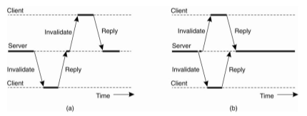
Figure 3.3(III)(a) Sending a invalidation message one at a time. (b) Sending invalidation messages in parallel.
The problem is occurs that an RPC may occasionally fail. Invalidating files in a strict sequential order may be delayed because the server cannot reach a possibly crashed client, but will give up on that client only after a relatively long expiration time. But other clients will still be reading from their local copies.
The better solution is shown in Fig.3.2 (b). In this instead of invalidating each copy one by one. The server sends an invalidation message to all clients at the same time. In this all non-failing clients are notified in the same time as it would take to do an immediate RPC. Also, the server notices within the usual expiration time that certain clients are failing to respond to the RPC, and declare such clients as being crashed.
Parallel RPCs are implemented as the MultiRPC system, which is part of the RPC2 package. An important aspect of MultiRPC is that the parallel invocation of RPCs is fully transparent to the callee that means the receiver of a MuitiRPC call cannot distinguish that call from a normal RPC. At the caller's side, parallel execution is also largely transparent. For example, the process of MultiRPC in the presence of failures are same as that of a normal RPC. Likewise, the side-effect mechanisms can be used in the same way as before used.
File-Oriented Communication in Plan 9
Plan 9 is not a distributed file system, but rather a file-based distributed system. All resources are accessed in the same way, namely with file-like syntax and operations, including resources such as processes and network interfaces. This idea is inherited from UNIX, which also attempts to offer file-like interfaces to resources.
To describe, network interfaces are represented by a file system, in this case consist of a collection of special files. This approach is same as to UNIX, but network interfaces in UNIX are represented by tiles and not file systems. In Plan 9 an individual TCP connection is represented by a subdirectory consisting of the files shown in Fig.
The file ctl is used to send control commands to the connection. For example, to open a telnet session to a machine with IP address 192.31.231.42 using port 23,requires that the sender writes the text string that is "connect 192.31.231.42!23" to file ctl. The receiver previously have written the string "announce 23" to its own ctl file, indicating that it can accept incoming session requests. The data file is used to exchange data by performing read and write operations. These operations follow the usual UNIX semantics for file operations.
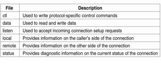
Figure 3.3(IV)shows the files associated with a single TCP connection in Plan 9.
For example, to write data to a connection, a process invokes the operation res = write(td, but, nbytes) where fd is the file descriptor returned after opening the data file, buf is a pointer to a buffer containing the data to be written, and nbytes is the number of bytes that should be fetched from the buffer. The number of bytes written is returned and stored in the variable res.
The file listen is used to wait for connection setup requests. After a process has announced it’s ready to accept new connections, it can do a blocking read on file listen. If a request comes in, the call returns a file descriptor to a new etl file to a newly-created connection directory.
Naming plays an important role in distributed file systems. In virtually all cases, names are organized in a hierarchical name space.
Naming in NFS
The idea of NFS naming model is to provide clients complete transparent access to a remote file system as maintained by a server. This transparency is achieved by a client be able to mount a remote file system into its own local file system shown in Fig. Instead of mounting full file system, NFS allows clients to mount only part of a file system. A server export a directory when it makes that directory and its entries available to clients. An exported directory can be mounted into a client's local name space.
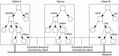
Figure 3.4 (I) shows mounting a remote file system in NFS.
This design approach users do not share name spaces. The file named Iremotelvulmbox at client A is named /work/me/mbox at client B. A file's name is depends onhow clients organize their own local name space, and where exported directories are mounted. The drawback of this approach is that sharing files becomes much harder. For example, Alice cannot tell Bob about afile using the name she assigned to that file, for that name have a different meaning in Bob's name space of files.
There are multiple ways to solve this problem, but the common way is to provide each client with a name space that is partly standardized. For example, each client may be using the local directory lusr/bin to mount a file system containing a standard collection of programs which are available to all. Likewise,the directory Ilocal may be used as a standard to mount a local file system that is located on the client's host.
The NFS server itself mount directories that are exported by other servers.
File Handles
A file handle provides a reference to a file within a file system. It is an independent of the name of the file which it refers. A file handle is created by the server that is hosting the file system and is unique with respect to all file systems exported by the server. It is created when the file is created. The client is not focus the actual content of a file handle; it is completely opaque. File handles were 32 bytes in NFS version 2, but variable up to 64 bytes in version 3 and 128 bytes inversion 4.
A file handle is implemented as a true identifier for a file relative to a file system. This means that as long as the file exists, it should have only one and the same file handle. This requirement allows a client to store a file handle locally once the associated file has been looked up by means of its name. It provides benefit is performance. File operations require a file handle instead of a name, the client can avoid having to look up a name repeatedly before every file operation. Another benefit of this approach is that the client can now access the file independent of its current names.
A file handle locally stored by a client, it is also important that a server does not reuse a file handle after deleting a file. Or a client may mistakenly access the wrong file when it uses its locally stored file handle.
The combination of iterative name lookups and a lookup operation allow crossing a mount point introduces a problem with getting an initial file handle. In order to access files in a remote file system, a client will need to provide the server with a file handle of the directory where the lookup should take place, along with the name of the file or directory that is to be resolved.
NFSv3 solves this problem through a separate mount protocol in which a client mounts a remote file system. After mounting, the client is passed back the root file handle of the mounted file system, which it can subsequently use as a starting point for looking up names.
Automounting
NFS naming model provides users with their own name space. Sharing in this model become difficult if users name the same file differently. The solution to this problem is to provide each user with a local name space that is partly standardized, and subsequently mounting remote file systems the same for each user.
Another problem with the NFS naming model is that deciding when are mote file system should be mounted. Consider that each user has a local directory /home that is used to mount the home directories of other users. For example, Alice's home directory may belocally available to her as /home/alice, the actual files are stored on a remote server. This directory can be automatically mounted when Alice logs into her workstation. In addition, she may have access to Bob's public files by accessing
Bob's directory through /home/bob.
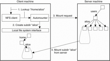
Figure 3.4 (II) shows a simple auto mounter for NFS.
Suppose that Alice logs in. The login program will attempt to read the directory /home/alice to find information such as login scripts. The automounter will receive the request to look up subdirectory /home/alice, forwhich it first creates a subdirectory /alice in /home. It then looks up theNFS server that exports Alice's home directory to subsequently mount that directoryin /home/alice. At that point, the login program can proceed.
The problem in this approach is the automounter will have to be involved in all file operations to guarantee transparency. If a referenced file is not locally available because the corresponding file system has not mounted,the automounter will have to know. It will need to handle all read and write requests for file systems that have already been mounted. This approach may incur a large performance problem. It would be better to have the automounter only mountlunmount directories, but otherwise stay out of the loop.
A simple solution is to the automounter mount directories in a specials ubdirectory, and install a symbolic link to each mounted directory. This is shown in fig. In example, the user home directories are mounted as subdirectories of/tmp _mnt. When Alice logs in, the automounter mounts her home directory in/tmp_mnt/home/alice and creates a symbolic link /home/alice that refers tosubdirectory. In this case Alice executes a command such asIs -I /home/alicethe NFS server that exports Alice's home directory is contacted directly withoutfurther involvement of the automounter.
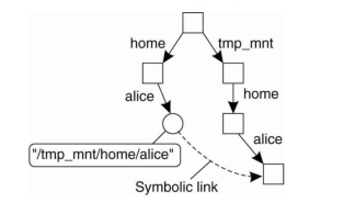
Figure 3.4 (III) shows automounting using symbolic links.
Constructing a Global Name Space
Large distributed systems constructed by combining together various legacy systems into one whole. It offers shared access to files, having a global name space is about the minimal glue that one would like to have. The file systems are opened for sharing by using primitive means such as access through FTP. This approach is used in Grid computing.
More approaches are followed by wide-area distributed file systems, but these require modifications to operating system kernels in order to be adopted. Therefore, researchers have been looking for approaches to integrate existing file systems into a single, global name space but using only user level solutions. This system is called Global Name Space Service(GNS) which is proposed by Anderson et a1.(2004).
GNS does not provide interfaces to access files. Instead of it provides the setup a global name space in which several existing name spaces have been merged. To this end, a GNS client maintains a virtual tree in which each node is either a directory or a junction. A junction is a special node that indicates name resolution is to be taken over by another process. There are five different types of junctions shown in Fig.

Fig 3.4 (IV) shows junctions in GNS.
The synchronization for file systems is not be an issue if files were not shared. Therefore in a distributed system, the rules of file sharing becomes a bit tricky when performance issues are at stake.
Semantics of File Sharing
When two or more users share the same file at the same time, it is required to define the rules of reading and writing to avoid problems. In single-processor systems that permit processes to share files, such as UNIX, the rules state that when a read operation follows a write operation, the read returns the value just written which is shown in fig (a).
Same as when two writes happen in quick succession, followed by a read, the value of read is the value stored by the last write. In effect, the system provides an absolute time ordering on all operations and always returns the most recent value. We will called to this model as UNIX semantics. This model is easy to understand and straightforward to implement.
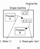
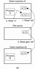
Figure 3.5 (I) shows (a) on a single processor when a read follows a write, the value returned by the read is the value just written. (b) In a distributed system withcaching obsolete values may be returned.
In a distributed system, UNIX semantics can be achieved easily with there is only one file server and clients do not cache files. All reads and writes go directly to the file server which processes them strict sequentially.
The performance of a distributed system in which all file requests must go to a single server is frequently poor. This problem is solved by allowing clients to maintain local copies of heavily-used files in their private caches.
In following figure we summarize the four approaches for dealing with shared files in a distributed system.

Figure 3.5 (II) shows four ways of dealing with the shared files in a distributed system.
File Locking
In client-server architectures with stateless servers, there is need additional facilities for synchronizing access to shared files. The traditional way of doing this is to make use of a lock manager. Without exception, a lock manager follows the centralized locking approach.
A central lock manager is generally deployed, the complexity in locking comes from the need to allow concurrent access to the same file. For this purpose, a great number of different locks exist, and the granularity of locks may also differ.
Consider the NFSv4 in this file locking is simple. There are four operations related to locking shown in fig. NFSv4 differentiate read locks from write locks. Multiple clients can at a time access the same part of a file provided they only read data. A write lock is needed to obtain exclusive access to modify part of a file.
Operation lock is used to request a read or write lock on a consecutive range of bytes in a file. It is a non-blocking operation in which if the lock cannot be granted due to another conflicting lock, the client gets back an error message and has to poll the server at a later time. There is no automatic retry.
Therefore the client can request to be put on a FIFO-ordered list maintained by the server. As soon as the conflicting lock has been removed, the server will grant the next lock to the client at the top of the list which provides to it polls the server before a certain time expires. This approach prevents the server from having to notify clients, while still being fair to clients whose lock request could not be granted because grants are made in FIFO that is First In First Out order.

Figure 3.5 (III) shows NFSv4 operations related to file locking.
In addition there is an implicit way to lock a file, referred as share reservation. Share reservation is completely independent from locking, and used to implement NFS for Windows-based systems.
When a client opens a file, it specifies the type of access it requires that is READ, WRITE or BOTH, and which type of access the server should deny other clients that is NONE, READ, WRITE, or BOTH. If the server can’t meet the client’s requirements, the open operation will fail for that client. Following figure show exactly what happens when a new client opens a file that has already been successfully opened by another client. For an already opened file there are two different state variables.
i. Access state: It specifies how the file is currently being accessed by the current client.
Ii. Denial state: It specifies what accesses by new clients are not permitted.
Fig. (a)Show what happens when a client tries to open a file requesting specific type of access, given the current denial state of that file.

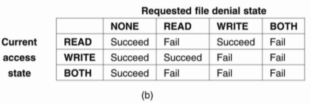
Figure 3.5 (IV) shows the result of an open operation with share reservations in NFS.
(a) The client requests shared access given the current denial state.
(b) The client requests a denial state given the current file access state.
Sharing Files in Coda
To perform file sharing, the Coda file system uses a special allocation scheme that have some similarities to share reservations in NFS. When a client successfully opens a file 1, an entire copy of f is transferred to the client's similar to open delegation in NFS. Suppose client A has opened file f for writing. When other client B Wants to open f as well then it will fail. This failure is occur because the server has recorded that client A might have already modified f. On other hand, client A opened f for reading, an attempt by client B to get a copy from the server for reading would succeed and attempt by B to open for writing is succeed also.
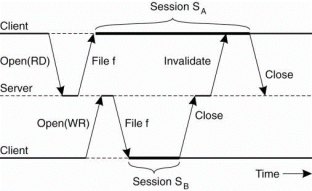
Figure 3.5 (V) shows the transactional behavior in sharing files in Coda.
Caching and replication is an important role in distributed file systems they are designed to operate over wide-area networks. In which we will take a look at various aspects related to client-side caching of file replication in peer-to-peer file-sharing systems.
Client-Side Caching
For Client side caching consider the example of NFS and Coda.
Caching in NFS
Caching in NFSv3 has been left outside of the protocol. This approach implementation of different caching policies, most of which never guaranteed consistency. Cached data could be stale for a few seconds compared to the data stored at a server. Therefore implementations allowed cached data to be stale for 30 seconds without the client knowing.
NFSv4 solves these consistency problems, but leaves cache consistency to be handled in an implementation-dependent way. The caching model is assumed by NFS is shown in Fig. Each client have a memory cache which contains data previously read from the server. There may also be a disk cache that is added as an extension to the memory cache, using the same consistency parameters.
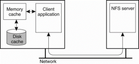
Figure 3.6(I) shows Client-side caching in NFS.
Client’s cache contains file data, attributes, file handles, and directories. Different ways exist to handle consistency of the cached data, cached attributes, and so on. NFSv4 supports two different approaches for caching file data. The simple approach is when a client opens a file and caches the data it obtains from the server as the result of various read operations and write operations can be carried out in the cache as well.
i. Open delegation takes place when the client machine is allowed to locally handle open and close operations from other clients on the same machine. The server is in charge of checking whether opening a file should succeed or not because share reservations need to be taken into account.
With open delegation, the client machine is allowed to make such decisions for avoiding the need to contact the server. The important consequence of delegating a file to a client is that the server needs to be able to recall the delegation, when another client on different machine needs to obtain access rights to the file. Performing a delegation requires that the server can do a callback to the client, as shown in fig.
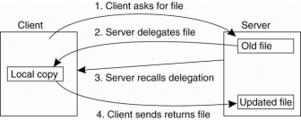
Figure 3.6(II)shows the NFSv4 callback mechanism to recall file delegation
Client-Side Caching in Coda
Client-side caching is crucial to the operation of Coda for two reasons. One is caching is done to achieve scalability and second caching provides a higher degree of fault tolerance because the client becomes less dependent on the availability of the server.
For above reasons, clients in Coda always cache entire files that means when a file is opened for either reading or writing, then entire copy of the file is transferred to the client, where it is cached.
In distributed file systems Cache coherence in Coda is maintained by means of callbacks. For every file, the server from which a client had fetched the file keeps track of which clients have a copy of that file cached locally.
A server is said to record a callback promise for a client. When a client updates its local copy of the file for the first time, it notifies the server that sends an invalidation message to the other clients. Such an invalidation message is called a callback break, because the server will then discard the callback promise given for the client it just sent an invalidation.
When client A starts session SA then the server records a callback promise. The same happens when B starts session that isSB. When B closes to SB the server breaks its promise to callback client A by sending a callback break. Due to the transactional semantics of Coda, when client A closes session SA the closing is simply accepted as one would expect.
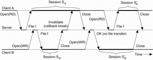
Figure 3.6(III) shows use of local copies when opening a session in Coda.
Server-Side Replication
In client-side caching a server-side replication in distributed file systems is less common. Replication is applied when availability is at stake, but from a performance perspective it makes more sense to deploy caches in which a whole file, or otherwise large parts of it, are made locally available to a client.
Another problem with server-side replication for performance is that a combination of a high degree of replication and a low read/write ratio degrade performance. This is easy to understand when realizing that every update operation needs to be carried out at every replica that means for an N-fold replicated file, a single update request will lead to an N-fold increase of update operations.
The concurrent updates need to be synchronized, leading to more communication and further performance reduction. Because of these file servers are generally replicated only for fault tolerance.
Following is the type of replication for the Coda file system.
Server Replication in Coda
Permission is assign by coda to file servers to be replicated. The unit of replications a collection of files called a volume. A volume related to a UNIX disk partition, that is, a traditional file system like the ones directly supported by operating systems that’s why volumes are generally much smaller.
The collection of Coda servers have a copy of a volume which is known as Volume Storage Group or VSG. In the presence of failures, a client does not have access to all servers in a volume's VSG. A client's Accessible Volume Storage Group (AVSG) for a volume contains servers in that volume's VSG that the client can contact at the moment.
The client disconnected when AVSG is empty. The Coda uses a replicated-write protocol to maintain consistency of a replicated volume. When a client needs to read a file, it contacts one of the members in its AVSG of the volume to which that file from. When closing a session on an updated file, the client transfers it in parallel to each member in the AVSG.
This works as there are no failures, that is, for each client, that client's AVSG of a volume is the same as its VSG. Consider a volume that is replicated across three servers 81, 82, and 83, for client A, assume its AVSG covers servers 81 and 82and client B has access only to server 83, as shown in Fig.
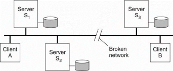
Figure 3.6(IV)shows two clients with a different AVSG for the same replicated file.
Replication in Peer-to-Peer File Systems
Replication plays an important role, for speeding up search and lookup requests, but also to balance load between nodes. An important property is that virtually all files are read only. Updates consist only in the form of adding files to the system. There are two types’ unstructured and structured peer-to-peer systems.
1)Unstructured Peer-to-Peer Systems
Fundamental to unstructured peer-to-peer systems is that looking up data boils down to searching that data in the network. This means that a node will simply have to, consider example, and broadcast a search query to its neighbors, from where the query may be forwarded. When files are replicated, searching becomes easier and faster.
Replication in unstructured peer-to-peer systems happens naturally when users download files from others and also make them available to the community. Controlling these networks is very difficult except when parts are controlled by a single organization.
2)Structured Peer-to-Peer Systems
In structured peer-to-peer systems, replication is deployed to balance the load between the nodes. The method is to replicate a file along the path thata query has followed from source to destination.
This replication policy effects on replicas that are placed close to the node responsible for storing the file, and it will be indeed offload that node when there is a high request rate. Therefore, such a replication policy does not take the load of other nodes into account, and may thus easily lead to an imbalanced system.
The principal idea is to store replicas at the source node of a query, and to cache pointers to such replicas in nodes with the query route from source to destination.
When a query from node P to Q is go through node R, R will check whether any of its files should be offloaded to P. It does simply looking at its own query load. If R is manages many lookup requests for files its currently storing in comparison to the load imposed on P, it can ask P to install copies of R's most requested files. This principle is shows in following fig.
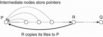
Figure 3.6(V)Balancing load in a peer-to-peer system by replication.
File Replication in Grid Systems
In many Grid applications data are read only. Data are produced from sensors, or from other applications, but rarely updated or modified after they are produced and stored. As a result, data replication can be applied in abundance.
Special measures need to be taken to avoid that data providers become overloaded due to the amount of data they need to transfer over the network. Because of the data is heavily replicated, balancing the load for retrieving copies is less of an issue.
Replication in Grid systems contains the problem of locating the best sources to copy data from. This problem can be solved by special replica location services, very similar to the location services we discussed for naming systems.
Basic Concepts
Fault tolerant is strongly related to dependable systems. Dependability is a term that covers a number of useful requirements for distributed systems includes
1. Availability
2. Reliability
3. Safety
4. Maintainability
Availability is known as the property that a system is ready to be used immediately.
Reliability means a system can run continuously without failure. A highly-reliable system continue to work without interruption during a relatively long period of time.
Safety consider as the situation that when a system temporarily fails to operate correctly, nothing catastrophic happens.
Maintainability refers to how easy a failed system can be repaired. A highly maintainable system may also show a high degree of availability when failures can be detected and repaired automatically.
A permanent fault is one that continues to exist until the faulty component is replaced. Burnt-out chips, software bugs, and disk head crashes are examples of permanent faults.
Failure Models
Consider a distributed system which is collection of servers that communicate with one another and with their clients, not providing services means that servers, communication channels, or possibly both, are not doing what they are supposed to do.
A malfunctioning server itself may not always be the fault that are looking for. If such a server depends on other servers to provide its services, the cause of an error may need to be searched for somewhere else.
This dependency relations appear in abundance in distributed systems. A failing disk make life difficult for a file server that is designed to provide a highly available file system. A file server is part of a distributed database, the proper working of the entire database may be at stake as its data may be accessible.
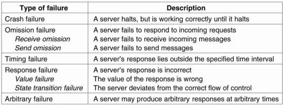
Figure 3.7(I) shows Different types of failures.
A crash failure occurs when a server prematurely halts that is take a break but working correctly until it stopped. An important aspect of crash failures is when the server has halted, nothing is heard from it anymore. Consider example of a crash failure is an operating system that comes to a grinding halt, and for which there is only one solution that is reboot it.
Personal computer systems have a crash failures so the people have come to expect them to be normal. Same time, moving the reset button from the back of a cabinet to the front was done for good reason. Perhaps one day it can be moved to the back again, or even removed altogether.
An omission failure occurs when a server fails to respond to a request by particular machine. In the case of a receive omission failure the server never got the request in the first place.
Failure Masking Redundancy
If a system is fault tolerant then try to hide the occurrence of failures from other processes. The key technique for masking faults is to use redundancy. Three are three types of redundancy information redundancy, time redundancy, and physical redundancy.
Information redundancy: If extra bits are added to allow recovery from garbled bits. For example, a Hamming code can be added to transmitted data to recover from noise on the transmission line.
Time redundancy: An action is performed, and then if need be, it is performed again
.
Physical redundancy: If extra equipment or processes are added to make it possible for the system as a whole to tolerate the loss or malfunctioning of some components. Physical redundancy can thus be done either in hardware or in software.
For example, extra processes can be added to the system so that if a small number of crash then the system can still function correctly. Physical redundancy is a useful technique for providing fault tolerance.
Following figure shows each device is replicated three times. Following each stage in the circuit is a triplicated voter. Each voter is a circuit that has three inputs and one output. If two or three of the inputs are the same, the output is equal to that input. If all three inputs are not same, the output is undefined. This design is known as TMR that is Triple Modular Redundancy.
Design Issues
The approach to tolerating a faulty process is to organize several identical processes into a group. The property that all groups have is that when a message is sent to the group itself, all members of the group receive it. In this way, if one process in a group fails, hopefully some other process can take over for it.
Process groups are may be dynamic. New groups are created and old groups are destroyed. A process can join a group or leave the group during system operation. A process can be a member of several groups at the same time.
The goal of introducing groups is to allow processes to deal with collections of processes as a single abstraction. Thus a process can send a message to a group of servers without having to know who they are or how many there are or where they are, which may change from one call to the next.
Flat Groups versus Hierarchical Groups
In some groups, all the processes are equal and no one is boss and all decisions are taken collectively. In other groups, some kind of hierarchy exists. For example, one process is the coordinator and all the others are workers. In this model, when a request for work is generated by an external client or by one of the workers, it is sent to the coordinator. The coordinator then decides which worker is best suited to carry it out, and forwards it there. These communication patterns are shown in Fig.
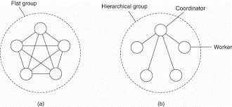
Figure3.8(I) (a) Communication in a flat group. (b) Communication in a simple hierarchical group.
Every fig in this organizations has its own advantages and disadvantages. The flat group is symmetrical and it has no single point of failure. If one of the processes crashes then the group becomes smaller, but can continue otherwise. A disadvantage is that decision making is most complicated. For example, to decide anything, a vote has to be taken, incurring some delay and overhead.
Group Membership
Group communication is present then some method is required for creating and deleting groups and also for allowing processes to join and leave groups. One approach is to have a group server to which all these requests are sent. The group server then maintain a complete data base of all the groups and their exact membership.
This method is straightforward, efficient, and easy to implement. Unfortunately, it has a major disadvantage with all centralized techniques: a single point of failure. If the group server crashes then group management ceases to exist. Probably most or all groups will have to be reconstructed from scratch and terminating whatever work was going on.
Failure Masking and Replication
Process groups is a part of the solution for building fault-tolerant systems. Containing a group of identical processes allows us to mask one or more faulty processes in that group.
There are two types of ways to approach such replication: by means of primary-based protocols, or through replicated-write protocols.
Primary-based replication in the case of fault tolerance appears in the form of a primary-backup protocol. In this case, a group of processes is organized in a hierarchical fashion in which a primary coordinates all write operations.
The primary is fixed and its role can be taken over by one of the backups if need be. In effect, when the primary crashes then the backups execute some election algorithm to choose a new primary.
The main advantage is such groups have no single point of failure, at the cost of distributed coordination. An important issue by using process groups to tolerate faults is how much replication is needed. To simplify consider only replicated write systems. A system is said to be k fault tolerant if it can survive faults in components and still meet its specifications. If the components, say processes, fail silently, then having k + 1 of them is enough to provide k fault tolerance. If k of them simply stop, then the answer from the other one can be used.
Agreement in Faulty Systems
Organizing replicated processes into a group helps to increase fault tolerance.
If a client can base its decisions through a voting mechanism, we can even tolerate that k out of 2k + 1 processes are lying about their result.
If matters become more intricate if we demand that a process group reaches an agreement, which is needed in many cases. Consider the examples electing coordinator, deciding whether or not to commit a transaction, dividing up tasks among workers and synchronization, among numerous other possibilities.
When the communication and processes are all perfect, reaching such agreement is straightforward, but when they are not, problems arise.
The general goal of distributed agreement algorithms is to have the non-faulty processes reach consensus on some issue, and to establish that consensus within a finite number of steps. The problem is complicated by the fact that different assumptions about the system require different solutions.
1. Synchronous versus asynchronous systems. A system is synchronous if and only if the processes are known to operate in a lock-step mode. A system that is not synchronous is said to be asynchronous.
2. Communication delay is bounded or not. Delay is bounded if and only if we know that every message is delivered with a globally and predetermined maximum time.
3. Message delivery is ordered or not. In other words, we distinguish the situation where messages from the same sender are delivered in the order that they were sent, from the situation in which we do not have such guarantees.
4. Message transmission is carried out through unicasting or multicasting.As it turns out, reaching agreement is only possible for the situations shown in Fig. Most distributed systems assume that processes behave asynchronously, message transmission is unicast, and communication delays are unbounded. As a consequence, we required to make use of reliable message delivery, such as provided as by TCP. Fig. Shows the nontrivial nature of distributed agreement when processes may fail.
The problem was studied by Lamport et al. (1982) and is known as the Byzantine agreement problem treated as the numerous wars in which several armies needed to reach agreement on. Consider the following solution which is described in Lamport et al. (1982). In this case processes are synchronous, messages are unicast while preserving ordering, and communication delay is bounded.
We assume that there are N processes and each process i will provide a value Vi to the others. The purpose is leteach process construct a vector V of length N, such that if process i is no faulty,V[iJ = Vi' Otherwise, V[i] is undefined. We consider that there are at most k faulty processes.
In following Fig.shows the working of the algorithm for the case of N = 4 and k = 1. The algorithm operates in four steps for these parameters.
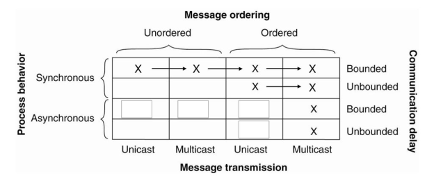
Figure 3.8(II) Circumstances under which distributed agreement can be reached.
Failure Detection
Failure detection is one of the cornerstones of fault tolerance in distributed systems. It boils down to that for a group of processes, non-faulty members are able to decide who is still a member, and who is not. When we want to detecting process failures, there are need only two mechanisms. Either processes actively send "are you alive?" messages to each other or passively wait until messages come in from different processes.
Failure detector use a timeout mechanism is used to check whether a process has failed. There are two problems with this approach. First is due to unreliable networks, simply stating that a process has failed because it does not return an answer to a ping message may be wrong.
Failure detection also done as a side-effect of regularly exchanging information with neighbors, as is the case with gossip-based information dissemination. This approach is essentially also adopted inObduro (Vogels, 2003) in this processes periodically gossip their service availability.
This information is distributed through the network by gossiping. Every process will know about every other process, but important iswill have enough information locally available to decide whether a process has failed or not.
The atomic multicasting problem is an example of a more general problem, known as distributed commit. The distributed commit problem contains an operation being performed by each member of a process group, or not at all. In the reliable multicasting, the operation is the delivery of a message. With distributed transactions, the operation maybe the commit of a transaction at a single site which takes part in the transaction.
Distributed commit is established by means of a coordinator. In a simple way, this coordinator tells all other processes that are also involved, called participants, whether or not to perform the operation in question. This scheme is known as a one-phase commit protocol.
It has drawback that if one of the participants cannot actually perform the operation, there is no way to tell the coordinator. For example, in the case of distributed transactions, a local commit may not be possible because this would violate concurrency control constraints.
Two-Phase Commit
The two-phase commit protocol (2PC) is due to Gray (1978)without loss of generality, consider a distributed transaction taking the participation of a number of processes each running on a different machine. Assuming that no failures occur, the protocol consists of the following two phases.
1. The coordinator sends a VOTE-REQUEST message to all other participants.
2. When a participant receives a VOTE-REQUEST message then it returns either a VOTE_COMMIT message to the coordinator indicating the coordinator that it is prepared to locally commit its part of the transaction, or otherwise a VOTE-ABORT message.
3.The coordinator collecting all votes from the participants. If all participants have voted to commit the transaction, then it be the coordinator. In this case, it sends a GLOBAL_COMMIT message to all participants. Therefore if one participant had voted to abort the transaction, the coordinator will also decide to abort the transaction and multicasts a GLOBALABORT message.
4. Each participant which are voted for a commit waits for the final reaction by the coordinator. When a participant receives a GLOBAL_COMMITmessage, it locally commits the transaction. Therefore when receiving a GLOBAL-ABORT message, the transaction is locally aborted also.
The first phase is the voting phase, it consists of steps 1 and 2. The second phase is the decision phase, and consists of steps 3 and 4. These four steps are shown as finite state in following fig.
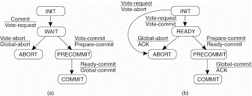
Figure 3.9(I) (a) The finite state machine for the coordinator in 2PC. (b) The finite state machine for a participant.
Multiple problems occurs in 2PC protocol is used in a system where failures occur. The coordinator and the participants having a states in which they block waiting for incoming messages. The protocol fail when a process crashes for other processes may be indefinitely waiting for a message from that process. For this reason timeout mechanism are used.
There are three states in which either a coordinator or participant is blocked waiting for an incoming message. First participant may be waiting in INIT state for a VOTE-REQUEST message from the coordinator. If that message is not received after some time, the participant will decide to locally abort the transaction, and send a VOTEABORT message to the coordinator.
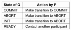
Figure 3.9(II) Actions taken by a participant P when residing in state READYand having contacted another participant Q.
Three-Phase Commit
A problem with the two-phase commit protocol is when the coordinator has crashed, participants may not be able to reach a final decision. Therefore participants may need to remain blocked until the coordinator recovers. Skeen(1981) developed a variant of 2PC this is called as three-phase commit protocol(3PC). It avoids blocking processes in the presence of fail-stop crashes.
Same as 2PC, 3PC is also formulated in terms of a coordinator and a number of participants. Their respective finite state machines is shown in Figure. The need of the protocol is that the states of the coordinator and each participant satisfy the following two conditions:
1. There is no single state from which it is possible to make a transition directly to either a COMMIT or an ABORT state.
2. There is no state in which it is not possible to make a final decision, and from which a transition to a COMMIT state can be made.
These two conditions are necessary and sufficient for a commit protocol to be no blocking.
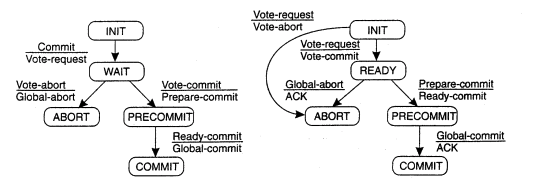
Figure shows3.9(III)(a) the finite state machine for the coordinator in 3PC. (b) The finite state machine for a participant.
The coordinator in 3PC send a VOTEREQUEST message to all participants, after which it waits for incoming responses. If any participant votes to abort the transaction, the final decision will be to abort as well, so the coordinators ends GLOBAL-ABORT. When the transaction is committed, a PREPARE_COMMIT message is sent. Only after each participant has acknowledged it is now prepared to commit then the coordinator send the final GLOBAL_COMMIT message by which the transaction is actually committed.
There are situations in which a process is blocked while waiting for incoming messages. When a participant is waiting for a vote request from the coordinator until it residing in state INIT, it will make a transit onto state ABORT, thereby assuming that the coordinator has crashed. This situation is identical to that in 2PC. The coordinator may be in state WAIT, waiting for the votes from participants. When a timeout, the coordinator consider that a participant crashed, and will thus abort the transaction by multicasting a GLOBAL-ABORT message.
A failure has occurred, it is required that the process where the failure happened can recover to a correct state. Recovery means recover to a correct state, and subsequently when and how the state of a distributed system can be recorded and recovered to, by means of check pointing and message logging.
Introduction
Working approach to fault tolerance is that the recovery from an error. Error is that part of a system that may lead to a failure. The idea of error recovery is to replace an erroneous code with an error-free state. There are two forms of error recovery.
In backward recovery, the main issue is to bring the system from its present erroneous state back into a previously correct state. To do this it will be necessary to record the system's state from time to time, and restore such a recorded state when things go wrong. Each time the system's present state is recorded, a checkpoint is said to be made.
Another form is forward recovery. In this when the system has entered an erroneous state, instead of moving back to a previous, check pointed state, an attempt is made to bring the system in a correct new state from which it can continue to execute. The problem with forward error recovery mechanisms is that it has to be known in advance which errors may occur.
The difference between backward and forward error recovery is explained by considering the implementation of reliable communication. The common approach to recover from a lost packet is to let the sender retransmit that packet. The packet retransmission establishes that we attempt to go back to previous, correct state, namely the one in which the packet that was lost is being sent. Reliable communication through packet retransmission is therefore an example of applying backward error recovery techniques.
Another method is erasure correction. In this a missing packet is constructed from other, successfully delivered packets. For example, in (n,k) block erasure code, a set of k source packets is encoded into a set of n encoded packets, such that any set of k encoded packets is sufficient to reconstruct the original k source packets.
Check pointing allows the recovery to a previous correct state. Many fault-tolerant distributed systems combine check pointing with message logging. In this case, after a checkpoint has been taken, a process logs its messages before sending them off.
Stable Storage
To able to recover to a previous state, it is necessary that information needed to enable recovery is safely stored. Safely means that recovery information survives process crashes and site failures, but possibly also various storage media failures. Stable storage plays an important role when it comes to recovery in distributed systems.
Storage comes in three categories. First there is ordinary RAM memory, which is wiped out when the power fails or a machine crashes. Next is diskstorage, which survives CPU failures but which can be lost in disk head crashes and last is stable storage which is designed to survive anything except major calamities such as floods and earthquakes. Stable storage can be implemented with a pair of ordinary disks which is shown in fig (a). Each block on drive 2 is an exact copy of the block on drive 1. When a block is updated, first the block on drive 1 is updated and verified then the same block on drive 2 is done.
Consider that the system crashes after drive 1 is updated but before the updateon drive 2, shown in Fig. (b).
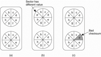
Figure 3.10(I) shows (a) Stable storage. (b) Crash after drive I is updated. (c) Badspot.
At the time of recovery the disk can be compared block for block. Whenever two corresponding blocks differ, it can be assumed that drive 1 is the correct therefore the new block is copied from drive 1 to drive 2. When the recovery process is complete, both drives will again be identical.
Checkpointing
In a fault-tolerant distributed system backward error recovery requires that the system regularly saves its state onto stable storage. In that we need to record a consistent global state is called a distributed snapshot. In distributed snapshot, if a process P has recorded the receipt of a message, then there is a process Q that has recorded the sending of that message.
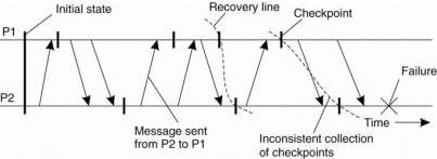
Figure 3.10(II) A recovery line.
In backward error recovery each process saves its state from time to time to a locally-available stable storage. To recover after a process or system failure requires that we construct a consistent global state from these local states. A recovery line corresponds to the most recent consistent collection of checkpoints shown in Fig.
1) Independent Check pointing
The distributed nature of check pointing may make it difficult to find a recovery line. To discover a recovery line requires that each process is rolled back to its most recently saved state. If these local states jointly do not form a distributed snapshot rolling back is necessary. Following a way to find a recovery line. This process of a cascaded rollback may lead to what is called the domino effect is shown in Fig.
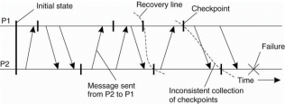
Figure 3.10(III)shows the domino effect.
When process P2 crashes, we need to restore its state to most recently saved checkpoint. A process P1will also need to be rolled back. If the two most recently saved local states do not form a consistent global state then the state saved by P2 indicates the receipt of a message m, but no other process can be identified as its sender. ThereforeP2 needs to be rolled back to an earlier state.
2) Coordinated Checkpointing
In coordinated checkpointing all processes synchronize to jointly write their state to local stable storage. The advantage of coordinated checkpointing is that the saved state is automatically globally consistent therefore cascaded rollbacks leading to the domino effect are avoided.
This algorithm is example of non blocking checkpoint coordination. A simpler solution is to use a two-phase blocking protocol. A coordinator first multicasts a CHECKPOINT, REQUEST message to all processes. When a process receives this message, it takes a local checkpoint and queues any subsequent message handed to it by the application it is executing, and acknowledges to the coordinator that it is has taken a checkpoint.
When the coordinator received an acknowledgment from all processes, it multicasts a CHECKPOINT-DONE message to allow the processes to continue.It is easy to see that this approach will also lead to a globally consistent state, because no incoming message will ever be registered as part of a checkpoint.
The reason is that any message that follows a request for taking a checkpoint isnot considered to be part of the local checkpoint. At the same time, outgoing messages are queued locally until the CHECKPOINT-DONE message is received.
Message Logging
Checkpointing is an expensive operation, especially concerning the operations involved in writing state to stable storage, techniques have been sought to reduce the number of checkpoints, but still enable recovery. An important technique in distributed systems is logging messages.
The idea behind message logging is that if the transmission of messages can be replayed, we can still reach a globally consistent state but without having to restore that state from stable storage. Instead, a checkpointed state is taken as a starting point, and all messages that have been sent since are simply retransmitted and handled accordingly.
This works under the assumption of what is called a piecewise deterministic model. In this model the execution of each process is assumed to take place as a series of intervals in which events take place. For example event may be the execution of an instruction, the sending of a message, and so on. Each interval in the piecewise deterministic model is considered to start with a nondeterministic event, such as the receipt of message. Therefore from that moment on, the execution of the process is completely different. An interval ends with the last event before a nondeterministic event occurs.
An orphan process is a process that survives the crash of another process and whose state is inconsistent with the crashed process after its recovery. For example consider the situation shown in Fig. Process Q receives messagesm1 and m2 from process P and R, respectively, and sends a messagem3 to R.In contrast to all other messages, message m2 is not logged.
If process Q crashes and later recovers again, only the logged messages required for the recovery of Q are replayed. In example m1becauseof m2 was not logged,its transmission will not be replayed that means the transmission of m3 also may not take place.
Characterizing Message-Logging Schemes
To characterize different message-logging schemes consider the approach described in Alvisi and Marzullo (1998). Each message m is considered to have a header that contains all information necessary to retransmit m, and to properly handle it.

Figure 3.10(IV) shows Incorrect replay of messages after recovery, leading to an orphan process.
For example, each header will identify the sender and the receiver, but also a sequence number to find out it as a duplicate. A delivery number may be added to decide when exactly it should be handed over to the receiving application. A message is said to be stable if it can no longer be lost, for example, because it has been written to stable storage. Stable messages can be used for recovery by replaying their transmission.
Recovery-Oriented Computing
The principle towards the way of masking failures is that it may be much cheaper to optimize for recovery, then it is aiming for systems that are free from failures for a long time. This approach is referred as recovery-oriented.
There are different types of recovery-oriented computing. One is simply reboot and has been explored to restart Internet servers. In order to be able reboot only a part of the system, it is crucial the fault is properly localized.
Rebooting means deleting all instances of the identified components along with the threads operating on them, and to just restart the associated requests. To enable rebooting as a practical recovery technique requires that components are largely decoupled in the sense that there are few or no dependencies between different components.
If there are strong dependencies, then fault localization and analysis may still require that a complete server needs to be restarted at which point applying traditional recovery techniques as the ones we just discussed may be more efficient.