Unit 3
Medium Access Control Sub Layer
Channel allocation is a process in which a single channel is divided and allotted to multiple users to carry user specific tasks. The user’s quantity may vary every time the process takes place.
If there are N number of users the channel is divided into N equal-sized sub channels, each user is assigned one portion. If the number of users is small and don’t vary at time,then Frequency Division Multiplexing can be used as it is a simple and efficient channel bandwidth allocating technique.
Static Channel Allocation in LANs and MANs:
It is the classical or traditional approach of allocating a single channel among multiple competing users FDM. If there are N users, the bandwidth is divided into N equal sized portions each user being assigned one portion.
Since each user has a private frequency band, there is no interface between users.
T = 1/ (U*C -L)
T(FDM) = N * T (1/U (C/N) – L/N)
Where
T = mean time delay
C = capacity of the channel,
L = arrival rate of frames
I/U = bits/frame
N= number of sub channels
It is not efficient to divide into fixed number of chunks.
T(FDM) = Frequency Division Multiplexing
2. Dynamic Channel Allocation:
Possible assumptions include:
Assumes that each of N stations independently produce frames. The probability of producing a packet in the interval IDt where I is the constant arrival rate of new frames.
2. Single Channel Assumption:
In this allocation all stations are equivalent and can send and receive on that channel.
3. Collision Assumption:
If two frames overlap in time-wise, then that’s collision. Any collision is an error, and both frames must re transmitted. Collisions are only possible error.
4. Time can be divided into Slotted or Continuous.
5. Stations can sense a channel is busy before they try it.
If there is a dedicated link between the sender and the receiver then data link control layer is sufficient, however if there is no dedicated link present then multiple stations can access the channel simultaneously. Hence multiple access protocols are required to decrease collision and avoid crosstalk.
For example, in a classroom full of students, when a teacher asks a question and all the students (or stations) start answering simultaneously (send data at same time) then a lot of chaos is created( data overlap or data lost) then it is the job of the teacher (multiple access protocols) to manage the students and make them answer one at a time.
Thus, protocols are required for sharing data on non- dedicated channels. Multiple access protocols can be subdivided further as –
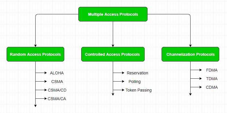
It has two features:
The Random- access protocols are further subdivided as:
(a) ALOHA – Aloha was designed for wireless LAN which is applicable for shared medium. In this, multiple stations can transmit data at the same time and can hence lead to collision and data being garbled.
When a station sends data it waits for an acknowledgement.
Vulnerable time = 2 * Frame transmission time
Throughput = G exp{-2 * G}
Maximum throughput = 0.184 for G=0.5
This is similar to pure aloha except that we divide time into slots and sending of data is allowed only at the beginning of these slots. If a station misses out the allowed time, it must wait for the next slot. This reduces the probability of collision.
Vulnerable time = Frame transmission time
Throughput = G exp{-*G}
Maximum throughput = 0.368 for G=1.
3.3 CSMA
CSMA is a network access method which is used on shared network topologies such as Ethernet to control access to the network.
Devices attached to the network cable listen (carrier sense) before transmitting. If the channel is in use, devices wait before transmitting.
MA (Multiple Access) indicates that many devices can connect to and share the same network.
All devices have equal access to use the network when it is clear.
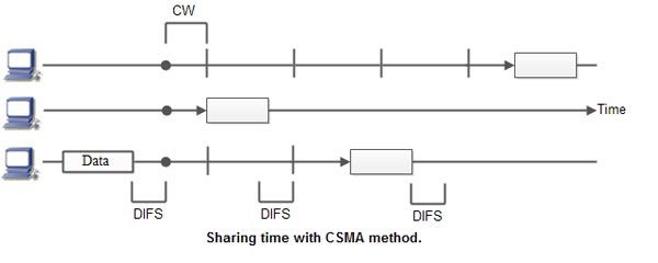
When a station wants to communicate “listen” first on the media communication and awaits a “silence” of a pre-set time (called the Distributed Inter Frame Space or DIFS).
After this compulsory period, the station starts a countdown for a random period considered. The maximum duration of this countdown is called the collision window (Window Collision, CW).
Consider the figure here the waiting time random has the advantage of allowing a statistically equitable distribution of speaking time between the various network equipment, while making little unlikely that both devices speak exactly the same time.
The countdown system prevents a station waiting too long before issuing its package. It’slike a bit what place in a meeting room when no master session expected a silencethen after few moments before speaking is allows time for someone else to speak.
CSMA protocol was developed to overcome the problem found in ALOHA to minimize the chances of collision, so as to improve the performance. CSMA protocol is based on the principle of ‘carrier sense’. The station senses the carrier or channel before transmitting a frame. It means the station checks the state of channel, whether it is idle or busy.
Even though devices attempt to sense whether the network is in use, there is a good chance that two stations will attempt to access it at the same time. On large networks, the transmission time between one end of the cable and another is enough that one station may access the cable even though another has already just accessed it.
The chances of collision still exist because of propagation delay. The frame transmitted by one station takes some time to reach other stations. In the meantime, other stations may sense the channel to be idle and transmit their frames. This results in the collision.
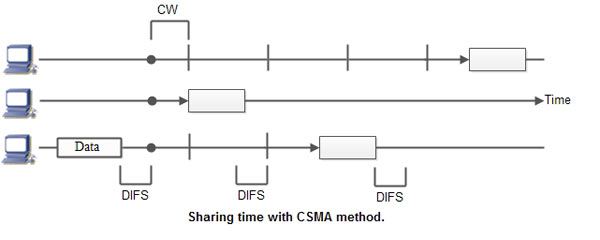
Collision – free protocols finds solution for collision in the contention period and so the possibilities of collisions are eliminated.
Types of Collision – Free Protocols
Bit – map Protocol
In bit map protocol, the contention period is divided into N slots, where N is the total number of stations sharing the channel. If a station has a frame to send, it sets the corresponding bit in the slot. Before transmission, each station knows whether the other stations want to transmit. Collisions are avoided by mutual agreement among the contending stations on who gets the channel.
Binary Countdown
This protocol overcomes the overhead of 1 bit per station of the bit – map protocol. Here, binary addresses of equal lengths are assigned to each station. For example, if there are 6 stations, they may be assigned the binary addresses 001, 010, 011, 100, 101 and 110. All stations wanting to communicate broadcast their addresses. The station with higher address gets the higher priority for transmitting.
Limited Contention Protocols
These protocols combine the advantages of collision based protocols and collision free protocols. Under light load, they behave like ALOHA scheme. Under heavy load, they behave like bitmap protocols.
Adaptive Tree Walk Protocol
In adaptive tree walk protocol, the stations or nodes are arranged in the form of a binary tree as follows -
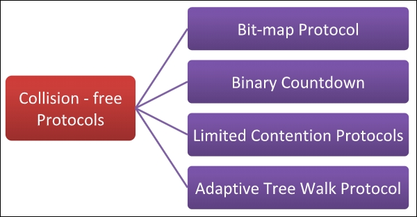
Initially all nodes (A, B ……. G, H) are permitted to compete for the channel. If a node is successful in acquiring the channel, it transmits its frame. In case of collision, the nodes are divided into two groups (A, B, C, D in one group and E, F, G, H in another group). Nodes belonging to only one of them is permitted for competing. This process continues until successful transmission occurs.
IEEE 802.3
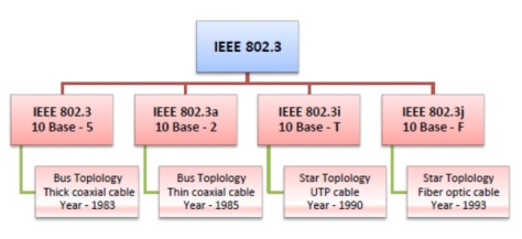
IEEE 802.3 defines the physical layer and medium access control (MAC) sub-layer of the data link layer for wired Ethernet networks.
Ethernet is classified into two categories: classic Ethernet and switched Ethernet.
Classic Ethernet is the original form of Ethernet that provides data rates between 3 to 10 Mbps. The varieties are commonly referred as 10BASE-X.
A switched Ethernet uses switches to connect to the stations in LAN. It replaces the repeaters used in classic Ethernet and allows full bandwidth utilization.
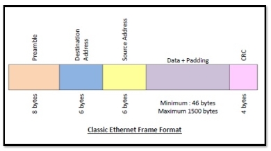
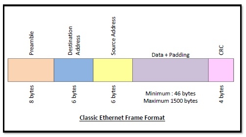
Frame Format of Classic Ethernet and IEEE 802.3
The main fields of a frame of classic Ethernet are -
CRC: CRC stands for cyclic redundancy check. It contains the error detection information.
802.4
Token Bus (IEEE 802.4)
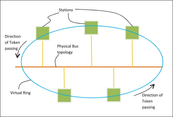
It is a standard for implementing token ring over the virtual ring in LANs. The physical media has a bus or a tree topology and uses coaxial cables. A virtual ring is created with nodes/stations and token is passed from one node to next in a sequence along this virtual ring.
Each node knows the address of its preceding station and its succeeding station. A station can only transmit data when it has the token.
Token Passing Mechanism in Token Bus
A token is a small message that circulates among the stations of a computer network providing permission to the stations for transmission. If a station has data to transmit when it receives a token, it sends the data and then passes the token to the next station or it simply passes the token to the next station.
This is shown in the diagram −
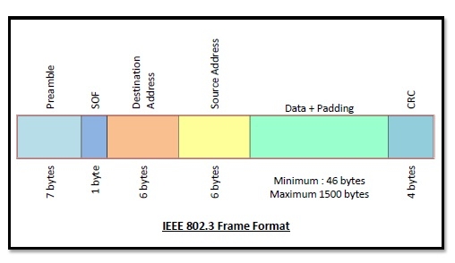
Frame Format of Token Bus
The frame format is given by the following diagram −
The fields of a token bus frame are −
802.5
IEEE 802.5 Token Ring:
It is a standard for a token-passing ring in Communication networks. A ring consists of a collection of ring interfaces connected by point-to-point lines that is ring interface of one station is connected to the ring interfaces of its left station as well as right station.
These point-to-point links can be created with twisted pair, coaxial cable or fiber optics. Each bit arriving at an interface is copied into a 1-bit buffer. In this buffer the bit is checked and may be modified and is then copied out to the ring again. This copying of bit in the buffer introduces a 1-bit delay at each interface.
Token Ring is a LAN protocol defined in the IEEE 802.5 where all stations are connected in a ring and each station can hear transmissions only from its immediate neighbour.
Permission to transmit is granted by a message (token) that circulates around the ring. A token is a special bit pattern (3 bytes long). There is only one token in the network.
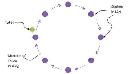
Token-passing networks move a small framecalled a token, around the network. If a node receiving the token in order to transmit data,it seizes the token, alters 1 bit of the token appends the information that it wants to transmit, and sends this information to the next station on the ring.
Since only one station can possess the token and transmit data at any given time, there are no collisions.There are two operating modes of ring interfaces. There are listen and transmit.
In listen mode, the input bits are simply copied to output with a delay of 1- bit time. In transmit mode the connection between input and output is broken by the interface so that is can insert its own data.
IEEE 802.11 is known as Wi-Fi which lays down the architecture and specifications of wireless LANs (WLANs). Wi-Fi or WLAN uses high frequency radio waves for connecting the nodes.
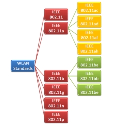
There are several standards of IEEE 802.11 WLANs. The prominent among them are 802.11, 802.11a, 802.11b, 802.11g, 802.11n and 802.11p. All the standards use carrier-sense multiple access with collision avoidance (CSMA/CA). They also have support for both centralised base- station based as well as ad-hoc networks.
IEEE 802.11
IEEE 802.11 was the original version released in 1997. It provided 1 Mbps or 2 Mbps data rate in the 2.4 GHz band that used either frequency-hopping spread spectrum (FHSS) or direct-sequence spread spectrum (DSSS).
IEEE 802.11a
802.11a was published in 1999 as a modification to 802.11 with orthogonal frequency division multiplexing (OFDM) based air interface in physical layer instead of FHSS or DSSS of 802.11. It provides a maximum data rate of 54 Mbps operating in 5 GHz band. Besides, it provides error correcting code. As 2.4 GHz band is crowded, relatively sparsely used 5 GHz imparts additional advantage to 802.11a.
IEEE 802.11b
802.11b is a direct extension of the original 802.11 standard that appeared in early 2000. It uses the same modulation technique as 802.11 that is DSSS and operates in 2.4 GHz band. It has higher data rate of 11 Mbps as compared to 2 Mbps of 802.11, due to which it was rapidly adopted in wireless LANs. However since 2.4 GHz band is pretty crowded 802.11b devices faces interference from other devices.
IEEE 802.11g
802.11g was indorsed in 2003. It operates in the 2.4 GHz band (as in 802.11b) and provides a average throughput of 22 Mbps. It uses OFDM technique (as in 802.11a). It is fully backward compatible with 802.11b. 802.11g devices also faces interference from other devices operating in 2.4 GHz band.
IEEE 802.11n
802.11n was approved and published in 2009 that operates on both the 2.4 GHz and the 5 GHz bands. It has variable data rate ranging from 54 Mbps to 600 Mbps. It provides marked improvement over previous standards 802.11 by incorporating multiple-input multiple-output antennas (MIMO antennas).
IEEE 802.11p
802.11 includes wireless access in vehicular environments (WAVE) to support Intelligent Transportation Systems (ITS). They include network communications between vehicles moving at high speed and the environment. They have a data rate of 27 Mbps and operate in 5.9 GHz band.
References:
1. Computer Networking: A Top-Down Approach Book by Jim Kurose
2. Computer Networks Book by Andrew S. Tanenbaum
3. Computer Networks: A Systems Approach Book by Bruce S. Davie and Larry L. Peterson
4. Computer Networking: Beginner's Guide for Mastering Computer ...Book by Ramon Nastase