Unit 5
Internet Protocol
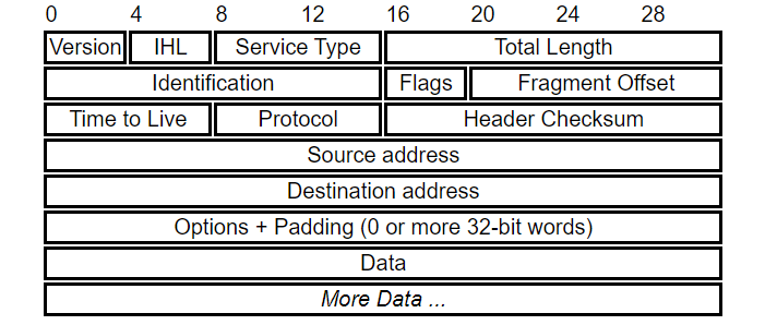
Header Contents
Version
Version of the IP protocol which determines how to interpret the header. The permitted values currently are 4 (0100) or 6 (0110). The header format shown here is valid for IPv4 only.
IHL
Length of header as a number is 32-bit words
Type of service
This field is often ignored by current routers but is meant to allow traffic to be prioritised.
Total Length
The length of the entire datagram including header and data: maximum permitted it 65,535 bytes or 64K.
Identification, Flags and Fragment Offset
These values allow datagrams to be fragmented for transmission and reassembled at the destination
Time to live
An integer which is decremented at each router "hop"; supposed to be interpreted as number of seconds but more often treated as a "hop count".
If the value reaches zero, datagram is discarded and an ICMP message is sent to the source host.
Protocol
Identifies the transport-layer protocol which will interpret the Data section.
Header checksum
This is used to verify the header and recomputed at each router hop. This field is left out of IPv6 which relies on the transport layer for verification.
Addresses and Options
These are 32-bit IP addresses which identify the network and host address. Routing requirements can also be specified in the Options field, along with options to do with security and debugging.
When the maximum size of datagram is greater than maximum size of data that can be held inframe that is its Maximum Transmission Unit (MTU) Fragmentation is done.
The network layer divides the datagram received from transport layer into fragments so that data flow is not disrupted.

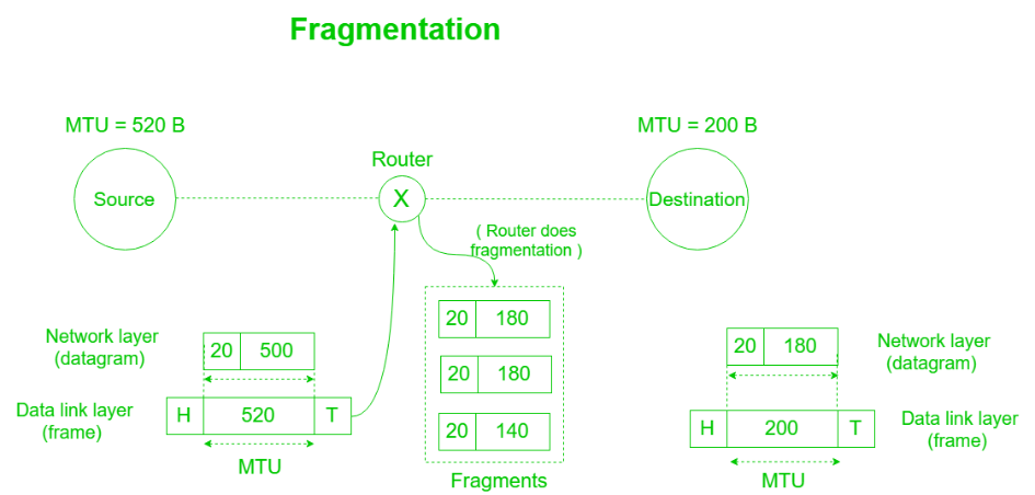
Fields in IP header for fragmentation –
Maximum fragment offset possible = (65535 – 20) – 1 = 65514
{where 65535 is maximum size of datagram and 20 is minimum size of IP header}
So, we need ceil(log265514) = 16 bits for fragment offset but fragment offset field has only 13 bits. So, to represent efficiently we need to scale down fragment offset field by 216/213 = 8 which acts as a scaling factor. Hence, all fragments except the last fragment should have data in multiples of 8 so that fragment offset ∈ N.
Since the packets take independent path it takes place at destination so all may not meet at router hence the need for fragmentation arises. The fragments may arrive out of order also.

Efficiency (e) = useful/total = (Data without header)/(Data with header)
Throughput = e * B { where B is bottleneck bandwidth }
Example – An IP router with a Maximum Transmission Unit (MTU) of 200 bytes has received an IP packet of size 520 bytes with an IP header of length 20 bytes. The values of the relevant fields in the IP header.
Explanation – Since MTU is 200 bytes and 20 bytes is header size so, the maximum length of data = 180 bytes but it can’t be represented in fragment offset since it is not divisible by 8 so, the maximum length of data feasible = 176 bytes.
Number of fragments = (520/200) = 3.
Header length = 5 (since scaling factor is 4 therefore, 20/4 = 5)
Efficiency, e = (Data without header)/(Data with header) = 500/560 = 89.2 %

When the actual communication happens over the physical address (MAC address)that isfrom layer 2 of OSI model then we get the destination MAC address which helps in communicating with other devices.
The functionality of translating IP address to physical address is done by ARP.
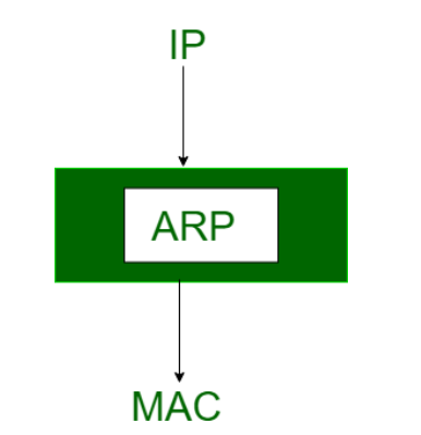
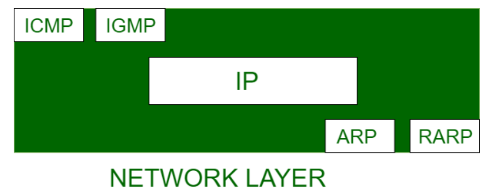
When a device wants to communicate with the other over the internet.
What ARP does? It broadcasts a packet to all the devices of the source network.
The devices of the network peel the header of the data link layer from protocol data unit (PDU) called frame and transfers the packet to the network layer where the network ID of the packet is validated with the destination IP’s network ID of the packet.
If it’s equal then it responds to the source with the MAC address of the destination, else the packet reaches the gateway of the network and broadcasts packet to the devices it is connected with and validates their network ID.
The above process continues till the second last network device in the path to reach the destination where it gets validated and ARP, in turn, responds with the destination MAC address.
RARP:
MAC addresses require individual configuration on the servers done by an administrator. RARP limits to the serving of IP addresses only.
When replacement machine is set up, the machine may or might not have an attached disk that may permanently store the IP Address so the RARP client program requests IP Address from the RARP server on the router.
The RARP server will return the IP address to the machine under the belief that an entry has been setup within the router table.
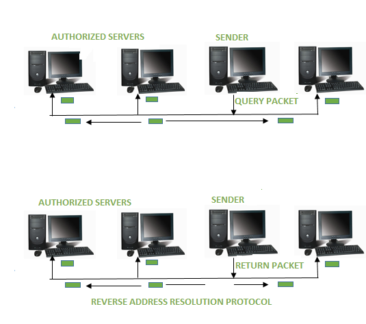
Working of RARP :
The RARP is on the Network Access Layer which is used to send data between two points in a network.
Each network participant has two unique addresses:-
IP address (a logical address) and
MAC address (the physical address).
The IP address gets assigned by software and after that the MAC address is constructed into the hardware.
The RARP server that responds to RARP requests, can be to any normal computer within the network. However, it must hold the data of all the MAC addresses with the assigned IP addresses.
If a RARP request is received by the network, these RARP servers can reply to it. The info packet needs to be sent on cheap layers of the network. This implies that the packet is transferred to all the participants at the identical time.
The client broadcasts a RARP request with an Ethernet broadcast address and with its own physical address. The server responds by informing the client its IP address.
ICMP
It is used for reporting errors and management queries. It is a supporting protocol and used by networks devices like routers for sending the error messages and operations information.
The primary purpose of ICMP is for error reporting. When two devices connect over the Internet, the ICMP generates errors to share with the sending device that data did not get to its intended destination.For example, if a packet of data is too large for a router, the router will drop the packet and send an ICMP message back to the original source for the data.
A secondary use of ICMP protocol is to perform network diagnostics; the commonly used terminal utilities traceroute and ping both operate using ICMP. The traceroute utility is used to display the routing path between two Internet devices.
The routing path is the actual physical path of connected routers that a request must pass through before it reaches its destination. The journey between one router and another is known as a ‘hop,’ and a traceroute also reports the time required for each hop along the way.
IGMP
Multicast communication can have single or multiple senders and receivers and thus, IGMP can be used in streaming videos, gaming or web conferencing tools. This protocol is used on IPv4 networks and for using this on IPv6, multicasting is managed by Multicast Listener Discovery (MLD). Like other network protocols, IGMP is used on network layer. MLDv1 is almost same in functioning as IGMPv2 and MLDv2 is almost similar to IGM.
References:
1. Computer Networking: A Top-Down Approach Book by Jim Kurose
2. Computer Networks Book by Andrew S. Tanenbaum
3. Computer Networks: A Systems Approach Book by Bruce S. Davie and Larry L. Peterson
4. Computer Networking: Beginner's Guide for Mastering Computer ...Book by Ramon Nastase